TMC-7DSP/TMC-6DSP Color CCD Camera ... - Site ftp Elvitec
TMC-7DSP/TMC-6DSP Color CCD Camera ... - Site ftp Elvitec
TMC-7DSP/TMC-6DSP Color CCD Camera ... - Site ftp Elvitec

You also want an ePaper? Increase the reach of your titles
YUMPU automatically turns print PDFs into web optimized ePapers that Google loves.
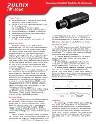
<strong>TMC</strong>-<strong>7DSP</strong>/<strong>TMC</strong>-<strong>6DSP</strong><br />
<strong>Color</strong> <strong>CCD</strong> <strong>Camera</strong><br />
Operation Manual<br />
September 10, 1999<br />
69-0059 Rev. A
Notice<br />
The material contained in this manual consists of information that is proprietary to PULNiX America, Inc., and may only<br />
be used by the purchasers of the product. PULNiX America, Inc. makes no warranty for the use of its product and assumes<br />
no responsibility for any errors which may appear or for damages resulting from the use of the information contained<br />
herein. PULNiX America, Inc. reserves the right to make changes without notice.<br />
Warranty<br />
All of our solid state cameras have a full three-year warranty. If any such product proves defective during this warranty<br />
period, PULNiX America, Inc. will repair the defective product without charge for parts and labor or will provide a<br />
replacement in exchange for the defective product. This warranty shall not apply to any damage, defect or failure caused<br />
by improper use or inadequate maintenance and use.<br />
CE Compliance<br />
Certifications<br />
The <strong>TMC</strong>-<strong>7DSP</strong>/<strong>TMC</strong>-<strong>6DSP</strong> has been certified to conform to the requirements of Council Directive 89/336/EC for<br />
electromagnetic compatibility and to comply with the following European Standards:<br />
Immunity: EN500082-2/1995<br />
Emissions: EN55022:1995 Class A / CISPR 22:1993<br />
All PULNiX products bearing the CE mark have been declared to be in conformance with the applicable EEC Council<br />
Directives. However, certain factory installed options or customer requested modifications may compromise<br />
electromagnetic compatibility and prohibit use of the CE mark. Please note that the use of interconnect cables that are not<br />
properly grounded and shielded may affect CE compliance.<br />
Contact the PULNiX Applications Engineering Department for further information regarding CE compliance.<br />
FCC<br />
This equipment has been tested and found to comply with the limits for a Class A digital device, pursuant to Part 15 of the<br />
FCC Rules. These limits are designed to provide reasonable protection against harmful interference when the equipment<br />
is operated in a commercial environment. This equipment generates, uses and can radiate radio frequency energy and, if<br />
not installed and used in accordance with the instruction manual, may cause harmful interference to radio<br />
communications. Operation of this equipment in a residential area is likely to cause harmful interference in which case the<br />
user will be required to correct the interference at his own expense.<br />
WARNING<br />
Changes or modifications to this unit not expressly approved by the party responsible<br />
for FCC compliance could void the user’s authority to operate the equipment.<br />
<strong>TMC</strong>-<strong>7DSP</strong>/TM-<strong>6DSP</strong> Operation Manual<br />
Printing: September 10, 1999<br />
PULNiX America, Inc.<br />
1330 Orleans Drive<br />
Sunnyvale, CA 94089<br />
Tel: (408) 747-0300<br />
Tel: (800) 445-5444<br />
Fax: (408) 747-0880<br />
E-mail: imaging@jaipulnix.com<br />
www.pulnix.com
Table of Content<br />
1 INTRODUCTION ..............................................................................................1<br />
1.1 Product Description and Applications.................................................................................1<br />
1.2 Features .............................................................................................................................1<br />
1.3 Functional Options..............................................................................................................2<br />
1.4 System Configuration .........................................................................................................3<br />
2 INSTALLATION................................................................................................4<br />
2.1 Getting Started ...................................................................................................................4<br />
2.1.1 Unpacking.................................................................................................................4<br />
2.1.2 Components List.......................................................................................................4<br />
2.1.3 Accessories and Options..........................................................................................4<br />
2.2 <strong>Camera</strong> Setup ....................................................................................................................5<br />
2.2.1 Connector Pin Configurations...................................................................................5<br />
2.2.2 Power Supply and Power Cable Setup.....................................................................5<br />
2.2.3 Attaching the Video Output.......................................................................................8<br />
2.2.4 Attaching the <strong>Camera</strong> Lens......................................................................................8<br />
2.2.5 Back Focusing the Lens ...........................................................................................8<br />
2.2.6 Auto-Iris Lens Setup (Optional) ................................................................................9<br />
2.2.7 Monitor Display Mode...............................................................................................9<br />
2.3 <strong>Camera</strong> Alinment and Adjustment......................................................................................9<br />
2.3.1 Equipment ................................................................................................................9<br />
3 OPERATION...................................................................................................11<br />
3.1 Modes of Operation..........................................................................................................11<br />
3.1.1 Shutter Control Functions.......................................................................................11<br />
3.1.2 <strong>Color</strong> Balance and Adjustment ..............................................................................11<br />
3.1.3 Jumper Swich (JSW)*.............................................................................................12<br />
3.1.4 White Balance Modes.............................................................................................12<br />
3.1.5 Software Control Features......................................................................................14<br />
3.2 Board Layout and Adjustment ..........................................................................................15<br />
3.2.1 Top Board ...............................................................................................................15<br />
3.2.2 Bottom Board..........................................................................................................15<br />
4 SOFTWARE INSTRUCTIONS .......................................................................16<br />
4.1 Software Installation .........................................................................................................16<br />
4.1.1 Before Installing <strong>TMC</strong>DSP Software.......................................................................16<br />
4.1.2 Installing <strong>TMC</strong>DSP Software ..................................................................................16<br />
4.1.3 Uninstalling <strong>TMC</strong>DSP.............................................................................................16<br />
4.2 Operating the Control Interface ........................................................................................17<br />
4.2.1 Before Running <strong>TMC</strong>DSP.EXE ...............................................................................17<br />
4.2.2 Shutter Mode Control .............................................................................................18<br />
4.2.3 White Balance Control............................................................................................19<br />
4.2.4 Gamma Control ......................................................................................................20<br />
4.2.5 Back Light Compensation Control ..........................................................................20<br />
4.2.6 Pedestal Control .....................................................................................................20<br />
4.2.7 Aperture Control .....................................................................................................21<br />
4.2.8 Gain Control ...........................................................................................................21<br />
4.2.8 Y Gain Control ........................................................................................................21<br />
4.2.9 Advanced Control ...................................................................................................21<br />
4.2.10 Write Current Setting ............................................................................................21<br />
i
Table of Contents<br />
4.2.11 Read Setting.........................................................................................................23<br />
4.3 Troubleshooting and FAQ .................................................................................................24<br />
4.3.1 Main Control Dialog Box Does Not Open ...............................................................24<br />
4.3.2 Advanced Controls Are Not Operational ................................................................24<br />
5 TROUBLESHOOTING ...................................................................................24<br />
5.1 Problems and Solutions....................................................................................................24<br />
5.1.1 Symptom: No Video................................................................................................24<br />
5.1.2 Symptom: Dark Video.............................................................................................25<br />
5.1.3 Symptom: Non-synchronized Video .......................................................................25<br />
5.2 Information and Support Resources.................................................................................25<br />
6 APPENDIX .....................................................................................................26<br />
6.1 Specifications ...................................................................................................................26<br />
6.1.1 Product Specifications............................................................................................26<br />
6.1.2 Physical Dimensions ..............................................................................................27<br />
6.1.3 Glass Specifications ...............................................................................................28<br />
6.1.4 C-Mount Specifications...........................................................................................28<br />
6.1.5 Front End Detail......................................................................................................29<br />
6.2 Imager <strong>Color</strong> Filters..........................................................................................................30<br />
6.1.1 Spectral Response with Complementary Mosaic Filter..........................................30<br />
6.1.2 Complementary Stripe Filter...................................................................................30<br />
6.3 Timing Chart .....................................................................................................................31<br />
6.4 Block Diagram ..................................................................................................................31<br />
ii
List of Figures<br />
FIGURE 1. <strong>TMC</strong>-<strong>7DSP</strong>/<strong>TMC</strong>-<strong>6DSP</strong> System Configuration ..............................13<br />
FIGURE 2.<br />
12P-02 Interface Cable (optional)...................................................16<br />
FIGURE 3. RS-232C Cable ..............................................................................17<br />
FIGURE 4. Shutter Control Settings .................................................................21<br />
FIGURE 5. <strong>TMC</strong>DSP Software Control Panel ..................................................24<br />
FIGURE 6. <strong>TMC</strong>-<strong>7DSP</strong>/<strong>TMC</strong>-<strong>6DSP</strong> Top Board ................................................25<br />
FIGURE 7.<br />
<strong>TMC</strong>-<strong>7DSP</strong>/<strong>TMC</strong>-<strong>6DSP</strong> Bottom Board...........................................25<br />
FIGURE 8. <strong>TMC</strong>DSP Control Dialog Box .........................................................27<br />
FIGURE 9.<br />
White Balance Control....................................................................29<br />
FIGURE 10. Setting Values in “User” External White Balance Mode..................30<br />
FIGURE 11. ASCII Text Format Example ...........................................................32<br />
FIGURE 12. Physical Dimensions ......................................................................37<br />
FIGURE 13. <strong>Camera</strong> Front End - Glass Specifications ......................................38<br />
FIGURE 14. C-Mount\.........................................................................................38<br />
FIGURE 15. Combination With “CS-Mount” <strong>Camera</strong> ..........................................39<br />
FIGURE 16. Front End Detail..............................................................................39<br />
FIGURE 17. Spectral Response .........................................................................40<br />
FIGURE 18. Complementary Stripe Filter Diagram ............................................40<br />
iii
September 10, 1999<br />
<strong>TMC</strong>-<strong>7DSP</strong>/<strong>TMC</strong>-<strong>6DSP</strong><br />
<strong>Color</strong> <strong>CCD</strong> <strong>Camera</strong><br />
Operation Manual<br />
1 INTRODUCTION<br />
1.1 Product Description and Applications<br />
The PULNiX <strong>TMC</strong>-<strong>7DSP</strong>/<strong>TMC</strong>-<strong>6DSP</strong> is a compact, high resolution color <strong>CCD</strong> camera offering the<br />
latest in high performance Digital Signal Process (DSP) technology. It is available in both NTSC (<strong>TMC</strong>-<br />
<strong>7DSP</strong>) and PAL (<strong>TMC</strong>-<strong>6DSP</strong>) formats.<br />
Rugged construction and high resistance to vibration and shock make these cameras particularly<br />
suitable for both industrial and CCTV surveillance applications. Offering superb color reproduction, the<br />
<strong>TMC</strong>-<strong>7DSP</strong>/<strong>TMC</strong>-<strong>6DSP</strong> is an excellent choice for a wide range of applications such as<br />
teleconferencing, machine vision, object recognition, medical systems, process monitoring, airborne<br />
imaging and remote observation.<br />
1.2 Features<br />
• High performance Digital Signal Processing (DSP)<br />
PULNiX uses state of the art DSP technology which offers increased speed, greater efficiency and<br />
specialization of function.<br />
• High sensitivity complementary color filter<br />
The <strong>TMC</strong>-<strong>7DSP</strong>/<strong>TMC</strong>-<strong>6DSP</strong> uses complementary stripe color filters of Cy, Gr, Ye. More sensitive<br />
than R, G, B primary color systems, a broader range of color variations are generated for<br />
outstanding color fidelity.<br />
• NTSC (<strong>TMC</strong>-<strong>7DSP</strong>) or PAL (<strong>TMC</strong>-<strong>6DSP</strong>), Y/C (S-Video), and RGB output (<strong>TMC</strong>-<strong>7DSP</strong><br />
only)<br />
Page 1
INTRODUCTION<br />
In addition to the standard VBS output, the <strong>TMC</strong>-<strong>7DSP</strong>/<strong>TMC</strong>-<strong>6DSP</strong> cameras feature separate<br />
outputs for the RGB signals with sync and Y/C output. RGB signals are output without the use of a<br />
“breakout” module. Separate RGB and sync signals can be output directly from the camera via the<br />
12-pin connector. Y/C output is available via the 6-pin connector. The Y signal also can be used for<br />
auto iris control.<br />
• 1/60 to 1/10,000 sec. programmable shutter and auto shutter<br />
The auto shutter function on the <strong>TMC</strong>-<strong>7DSP</strong>/<strong>TMC</strong>-<strong>6DSP</strong> adjusts the shutter speed automatically to<br />
maintain a wide dynamic range of video output (5 lux to 50,000 lux). This eliminates the need for<br />
bulky, expensive auto iris lenses.<br />
• RS-232C external control<br />
Many functions, including gain, white balance, gamma, aperture, hue control, and shutter control<br />
can be controlled externally via a PC.<br />
• Anti-smear filter<br />
Like all PULNiX color cameras, the <strong>TMC</strong>-<strong>7DSP</strong>/<strong>TMC</strong>-<strong>6DSP</strong> camera contains a filter to minimize<br />
smear that can result when shooting a very bright object. Smear should only occur under extremely<br />
bright and point light source conditions.<br />
• External sync (HD, VD sync) capability<br />
The <strong>TMC</strong>-<strong>7DSP</strong>/<strong>TMC</strong>-<strong>6DSP</strong> accepts external HD-VD or composite sync.<br />
• Three Year Warranty<br />
The <strong>CCD</strong> solid state image sensor allows the camera to maintain a superior performance level<br />
indefinitely while requiring virtually no maintenance. PULNiX backs all of the TM Series cameras<br />
with a three-year warranty.<br />
Warning:<br />
Unscrewing the camera cover or opening the camera in any way<br />
will void this warranty.<br />
1.3 Functional Options<br />
• Standard or mini cylindrical remote head configurations (one meter separation)<br />
• Custom remote imager lengths<br />
Page 2<br />
<strong>TMC</strong>-<strong>7DSP</strong>/<strong>TMC</strong>-<strong>6DSP</strong> <strong>Color</strong> <strong>CCD</strong> <strong>Camera</strong>
95 6 7 8<br />
2<br />
4<br />
3<br />
INTRODUCTION<br />
1.4 System Configuration<br />
Figure 1 (below) presents a typical system configuration.<br />
FIGURE 1.<br />
<strong>TMC</strong>-<strong>7DSP</strong>/<strong>TMC</strong>-<strong>6DSP</strong> System Configuration<br />
Auto-Iris Lens<br />
(optional)<br />
Power<br />
Ext. Sync<br />
Integration<br />
Video Output*<br />
OPTION<br />
SHUTTER PWR/RGB<br />
01<br />
MODE<br />
VIDEO<br />
1 2 3 4<br />
AWB<br />
Computer with<br />
Frame Grabber<br />
Board<br />
* Video Output is the<br />
same as BNC connector<br />
Monitor<br />
<strong>TMC</strong>-<strong>7DSP</strong>/<strong>TMC</strong>-<strong>6DSP</strong> <strong>Color</strong> <strong>CCD</strong> <strong>Camera</strong> Page 3
INSTALLATION<br />
2 INSTALLATION<br />
The following instructions are provided to help you to set up your video camera system quickly and<br />
easily. It is suggested that you read through these instructions prior to unpacking and setting up your<br />
camera system<br />
2.1 Getting Started<br />
2.1.1 Unpacking Instructions<br />
It is recommended that the original packing cartons for the cameras and lenses be saved in case there is<br />
a need to return or exchange an item. It is also recommended that any equipment being sent to another<br />
location for field installation be bench tested to assure that everything is fully operational as a system.<br />
2.1.2 Components List<br />
Please begin by checking your order against the Components List (below) to assure that you have<br />
received everything as ordered, and that nothing has been overlooked in the packing materials. If any<br />
item is missing, please contact your PULNiX representative immediately.<br />
• <strong>TMC</strong>-<strong>7DSP</strong>/<strong>TMC</strong>-<strong>6DSP</strong> camera<br />
• <strong>TMC</strong>-<strong>7DSP</strong>/<strong>TMC</strong>-<strong>6DSP</strong> data sheet<br />
2.1.3 Accessories and Options<br />
Following is a list of additional accessories and options that may be recommended or required for your<br />
particular application. Please check with your PULNiX representative prior to the installation of your<br />
video system to determine what you might need.<br />
• CamCom <strong>TMC</strong><strong>7DSP</strong>/<strong>6DSP</strong> Software<br />
• RS-232C cable<br />
• K25-12, K-50-12, or PD-12P power supply<br />
• 12P-02 power cable<br />
• DSP-2YC, Y/C output cable with RS-232<br />
• CBL-2R-7D, RGB output cable (for use with <strong>TMC</strong>-<strong>7DSP</strong> only)<br />
• <strong>TMC</strong>-<strong>7DSP</strong>/<strong>TMC</strong>/<strong>6DSP</strong> Operation Manual<br />
Page 4<br />
<strong>TMC</strong>-<strong>7DSP</strong>/<strong>TMC</strong>-<strong>6DSP</strong> <strong>Color</strong> <strong>CCD</strong> <strong>Camera</strong>
INSTALLATION<br />
2.2 <strong>Camera</strong> Setup<br />
2.2.1 Connector Pin Configurations<br />
2.2.1 (a) 12-Pin Connector<br />
The <strong>TMC</strong>-<strong>7DSP</strong>/<strong>TMC</strong>-<strong>6DSP</strong> has a 12-pin connector for power input. Pin #1 is<br />
Ground and Pin #2 is +12V DC. The other pins handle a number of other input<br />
and output functions, as detailed below.<br />
Pin Description Pin Description<br />
3<br />
2<br />
4<br />
1 9<br />
10<br />
11 12<br />
5<br />
8<br />
6<br />
7<br />
1 GND 7 Ext. Vd<br />
2 +12V DC 8 GND<br />
3 GND 9 Ext. Hd<br />
4 Video out (VBS) 10 R out (<strong>TMC</strong>-<strong>7DSP</strong> only)<br />
5 GND 11 G out (<strong>TMC</strong>-<strong>7DSP</strong> only)<br />
6 Sync out 12 B out (<strong>TMC</strong>-<strong>7DSP</strong> only)<br />
2.2.1 (b) 6-Pin Connector<br />
6 1<br />
The <strong>TMC</strong>-<strong>7DSP</strong>/<strong>TMC</strong>-<strong>6DSP</strong> has a 6-pin connector for RS-232C communication<br />
and Y/C. A mating 6-pin connector (PC-6P) can be obtained from PULNiX.<br />
5<br />
2<br />
Standard<br />
4 3<br />
Pin Description<br />
1 RS-232 RX<br />
2 RS-232 TX<br />
3 NC (12V DC opt.)*<br />
4 Y (video)<br />
5 C<br />
6 GND<br />
* For Pin #3, 12V DC is optional for auto iris control.<br />
2.2.2 Power Supply and Power Cable Setup<br />
2.2.2 (a) Power Supplies<br />
The <strong>TMC</strong>-<strong>7DSP</strong> requires 12 V DC. The 12pin connector is located at the rear of the camera. PULNiX<br />
recommends the following power supplies:<br />
K25-12 110V AC/12V DC 2.1A power supply<br />
K50-12 110V AC/12V DC 4.2A power supply<br />
PD-12P 110V AC/12V DC 0.5A power supply<br />
<strong>TMC</strong>-<strong>7DSP</strong>/<strong>TMC</strong>-<strong>6DSP</strong> <strong>Color</strong> <strong>CCD</strong> <strong>Camera</strong> Page 5
INSTALLATION<br />
For users providing power through the 12-pin connector, the PD-12P power supply is available with the<br />
12-pin mating connector already attached to the leads from the power supply. The PD-12 power supply<br />
can be connected to the PULNiX power cable via a terminal strip or directly.<br />
When wiring the PD-12 power supply directly, please note the following:<br />
• Twist the lead ends together and tin solder for strength and electrical continuity.<br />
• Use shrink tubing or a similar insulator to prevent exposed leads from touching.<br />
• The +12V lead is marked with a red stripe or white lettering; be sure not to reverse the leads.<br />
• Properly insulate all connections to prevent shorting.<br />
2.2.2 (b) PULNiX Power Cables<br />
If you are using PULNiX power cables, such as the 12P-02, KC-10, etc., please refer to the pin-out<br />
diagram. The color coded leads use Grey for Ground and Yellow for +12V DC.<br />
FIGURE 2.<br />
12P-02 Interface Cable (optional)<br />
GND (Gray)<br />
+12 V<br />
Power (Yellow)<br />
Video Out (Red Coax)<br />
HD In (White Coax)<br />
VD In (Black Coax)<br />
12P-02 Interface Cable<br />
Pin# Lead <strong>Color</strong> Function Pin# Lead <strong>Color</strong> Function<br />
1 Gray GND 7 Black coax signal Ext. Vd<br />
2 Yellow +12VCD 8 White coax shield GND<br />
3 Red coax shield GND 9 White coax signal Ext. Hd<br />
4 Red coax signal Video out(VBS) 10 Brown R out*<br />
5 Orange coax shield GND 11 Blue G out*<br />
6 Orange coax signal Sync out 12 Black coax shield B out*<br />
* Not recommended for RGB Output<br />
Note:<br />
Make sure that the unused leads are not touching and that there is no possibility that<br />
the leads could short due to exposed wires.<br />
2.2.2 (c) “K” Series Power Supplies<br />
Attach the 110V line cord to the two terminals marked “AC”. Do not plug the cord into a 110V AC<br />
socket until later in the procedure. Next, attach the Grey and Yellow leads of the power cable to the<br />
Page 6<br />
<strong>TMC</strong>-<strong>7DSP</strong>/<strong>TMC</strong>-<strong>6DSP</strong> <strong>Color</strong> <strong>CCD</strong> <strong>Camera</strong>
INSTALLATION<br />
Ground and 12V DC terminals respectively. Be sure to replace the plastic terminal guard on the power<br />
supply at this time.<br />
Note:<br />
The “K” series power supplies are designed primarily for OEM users who will be<br />
mounting the power supply inside a protective enclosure. For use in exposed situations,<br />
the DC-12N and PD-12 are recommended.<br />
2.2.2 (d) CBL-2R-7D RGB and Video Output Cable<br />
FIGURE 3.<br />
CBL-2R-7D<br />
RED<br />
GREEN<br />
BLUE<br />
SYNC<br />
C. Video<br />
<strong>TMC</strong>-<strong>7DSP</strong>/<strong>TMC</strong>-<strong>6DSP</strong> <strong>Color</strong> <strong>CCD</strong> <strong>Camera</strong> Page 7
INSTALLATION<br />
2.2.2 (e) DSP-2YC RS-232 Control and Y/C Output Cable<br />
FIGURE 4.<br />
DSP-2YC Cable<br />
RX<br />
TX<br />
Ground<br />
RS-232<br />
PC<br />
COM<br />
Frame<br />
Grabber<br />
OR<br />
PC COM<br />
Monitor<br />
YEL<br />
GRY<br />
BLU<br />
PIN1<br />
PIN2<br />
PIN3<br />
PIN4<br />
PIN5<br />
PIN6<br />
PIN7<br />
DCD<br />
RxD<br />
TxD<br />
DRT<br />
GND<br />
DSR<br />
RST<br />
NC<br />
NC<br />
PIN8<br />
PIN9<br />
CTS<br />
RI<br />
Page 8<br />
<strong>TMC</strong>-<strong>7DSP</strong>/<strong>TMC</strong>-<strong>6DSP</strong> <strong>Color</strong> <strong>CCD</strong> <strong>Camera</strong>
INSTALLATION<br />
2.2.2 (f) RS-232C-9 Communication Cable and Connector (optional)<br />
The <strong>TMC</strong>-<strong>7DSP</strong>/<strong>TMC</strong>-<strong>6DSP</strong> camera’s built-in microcomputer chip (CPU) can be controlled by an<br />
external RS-232C interface. The RS-232C-9 cable (Figure 5, “RS-232C-9 Cable”) connects to the 6-<br />
pin connector on the rear of the camera. The internal CPU controls the <strong>TMC</strong>-<strong>7DSP</strong>/<strong>TMC</strong>-<strong>6DSP</strong><br />
camera’s operation mode and DSP parameter changes. Contact PULNiX for the <strong>TMC</strong>-<strong>7DSP</strong>/<strong>TMC</strong>-<br />
<strong>6DSP</strong> software diskette.<br />
FIGURE 5.<br />
RS-232C-9 Cable<br />
6-PIN CONNECTOR<br />
D-SUB 9-PIN CONNECTOR<br />
RXD PIN 2 PIN 1 DCD<br />
TXD PIN 2 PIN 2 RXD<br />
+12V PIN 3 PIN 3 TXD<br />
Y out PIN 4 PIN 4 DTR<br />
C out PIN 5 PIN 5 GND<br />
GND PIN 6 PIN 6 DSR<br />
PIN 7<br />
PIN 8<br />
PIN 9<br />
RTS<br />
CTS<br />
RI<br />
2.2.2 (g) Building Your Own Power Cable<br />
Consult the pin-out for the camera purchased. Connect the Ground and +12V power leads of the PC-<br />
12P power connector (Part #PC-12P) to Pin #1 and Pin #2, respectively (power must be DC regulated,<br />
and of sufficient current to properly power the camera).<br />
<strong>TMC</strong>-<strong>7DSP</strong>/<strong>TMC</strong>-<strong>6DSP</strong> <strong>Color</strong> <strong>CCD</strong> <strong>Camera</strong> Page 9
INSTALLATION<br />
2.2.2 (h) Attaching the Power Cable to the Connector<br />
The 12-pin connector is keyed and will only fit in one orientation. Rotate the connector while applying<br />
slight pressure until the keyways line up. Press the connector into place until firmly seated.<br />
The power cord may now be plugged into the 110V AC socket, and the camera powered up.<br />
2.2.3 Attaching the Video Output<br />
Most users utilize the BNC connector for video output from the camera. Connect the output from the<br />
camera to the input of your monitor, VCR or switching device. The input of the monitor should be<br />
balanced for 75Ω termination. Standard RG-59 type coaxial cable should carry a full video signal for up<br />
to 500 feet.<br />
Users wishing to output the video and input the power and sync to a camera over a single cable can use<br />
the PULNiX multi-conductor cables, such as the 12P-02, the KC-10, etc. The mini coaxial leads in<br />
PULNiX multi-conductor cables are designed for short runs of no longer than 100 feet.<br />
Note: Make sure that no extraneous wires are visible which could cause a short.<br />
2.2.4 Attaching the <strong>Camera</strong> Lens<br />
The <strong>TMC</strong>-<strong>7DSP</strong>/<strong>TMC</strong>-<strong>6DSP</strong> camera accepts 1/2" or larger format size C-mount lenses. To attach the C-<br />
mount lens to the camera, carefully engage the threads and rotate the lens clockwise until it firmly seats<br />
on the mounting ring. Do not force the lens if it does not seat properly. Please note that some lenses with<br />
extremely long flangebacks may exceed the mounting depth of the camera.<br />
2.2.5 Back Focusing the Lens<br />
To backfocus the <strong>TMC</strong>-<strong>7DSP</strong>/<strong>TMC</strong>-<br />
<strong>6DSP</strong> camera, first attach a C-mount lens<br />
in the lens mount. Be sure that the lens is<br />
properly mounted.<br />
Back focus ring<br />
Set the lens focus to infinity (if the lens is<br />
a manual iris, set the iris to a high f-stop<br />
Back focus 2 ft.<br />
while still retaining a well-illuminated<br />
image). Obtain the best focus possible at<br />
this setting, then loosen the three miniature hex head set screws locking the focus ring in place. Now<br />
turn the entire lens and focus ring assembly back and forth until the best image is obtained. Tighten the<br />
focus ring set screws. Your backfocus is now set.<br />
2.2.6 Auto-Iris Lens Setup (Optional)<br />
The auto-iris option allows auto-iris lenses with full video input to be used with the PULNiX <strong>TMC</strong>-<br />
<strong>7DSP</strong>/<strong>TMC</strong>-<strong>6DSP</strong> via the 6-pin connector located on the back of the camera. A mating 6-pin connector<br />
(PC-6P) may be obtained from PULNiX. See Section 2.2.1 (b), “6-Pin Connector”, on page 5 for<br />
connections.<br />
Page 10<br />
<strong>TMC</strong>-<strong>7DSP</strong>/<strong>TMC</strong>-<strong>6DSP</strong> <strong>Color</strong> <strong>CCD</strong> <strong>Camera</strong>
INSTALLATION<br />
Note:<br />
Make sure that the power is removed from the camera before connecting or<br />
disconnecting the auto-iris lens. There is a small chance that damage could occur to<br />
the auto-iris lens by plugging or unplugging it while the camera is powered up.<br />
Power down the camera before installing the auto-iris lens. Point the camera at a light area and then<br />
quickly towards a darker area. If everything is working properly, the iris should adjust for the light<br />
change.<br />
2.2.7 Monitor Display Mode<br />
For monitoring real time video, connect the video output to a video monitor or other device.<br />
2.3 <strong>Camera</strong> Alignment and Adjustment<br />
2.3.1 Equipment<br />
2.3.1 (a) Light Source for Test Chart<br />
Pattern Box PTB-500 (90-130V)<br />
PTB-220 (190-240V) (not used in the U.S.)<br />
2.3.1 (b) Video and Gamma Adjustment<br />
<strong>TMC</strong>-<strong>7DSP</strong>/<strong>TMC</strong>-<strong>6DSP</strong> <strong>Color</strong> <strong>CCD</strong> <strong>Camera</strong> Page 11
OPERATION<br />
2.3.1 (c) <strong>Color</strong> Bar Chart for <strong>Color</strong> Adjustment<br />
YL CY G W MG R B<br />
2.3.1 (d) Signal Adjustment<br />
Vector Scope<br />
Waveform monitor<br />
Oscilloscope<br />
3 OPERATION<br />
3.1 Modes of Operation<br />
3.1.1 Shutter Control Functions<br />
3.1.1 (a) Electronic Shutter Control<br />
The capability to externally vary the electronic shutter rate from 1/60 sec. to 1/10,000 sec. is a standard<br />
feature of the <strong>TMC</strong>-<strong>7DSP</strong>/<strong>TMC</strong>-<strong>6DSP</strong> camera. The <strong>TMC</strong>-<strong>7DSP</strong>/<strong>TMC</strong>-<strong>6DSP</strong> camera has a substrate<br />
drain type shutter mechanism which results in a superb picture at various speeds with smearing.<br />
Electronic shuttering eliminates the need for costly and distracting strobe lights on high speed assembly<br />
or inspection lines.<br />
3.1.1 (b) Auto Shutter Mode<br />
Auto shutter (electronic iris control) is available by selecting the SW4 (up) on the rear panel, or by<br />
selecting externally via a PC (see Section 4.2.2, “Shutter Mode Control,” on page 20).<br />
FIGURE 6.<br />
Shutter Control Settings<br />
Page 12<br />
<strong>TMC</strong>-<strong>7DSP</strong>/<strong>TMC</strong>-<strong>6DSP</strong> <strong>Color</strong> <strong>CCD</strong> <strong>Camera</strong>
5<br />
OPERATION<br />
Switch NTCS PAL<br />
0 1/60 1/50<br />
1 1/100 1/120<br />
2 1/250 1/250<br />
3 1/500 1/500<br />
4 1/1,000 1/1,000<br />
5 1/2,000 1/2,000<br />
6 1/4,000 1/4,000<br />
7 1/10,000 1/10,000<br />
8 (not used)<br />
9 (not used)<br />
7<br />
9<br />
8<br />
6<br />
0 1 2<br />
4<br />
3<br />
Shutter Control Switch<br />
3.1.2 <strong>Color</strong> Balance and Adjustment<br />
The <strong>TMC</strong>-<strong>7DSP</strong>/<strong>TMC</strong>-<strong>6DSP</strong> cameras feature an advanced color balancing system which is controlled<br />
by DSP (Digital Signal Processing). Upon powering up, the camera will load the color balance setting<br />
from the internal EEPROM.<br />
3.1.3 Jumper Switch (JSW)*<br />
8 7 6 5 4 3 2 1<br />
JSW - Inside camera<br />
jumper switch<br />
FLON<br />
BLCOF<br />
MIRIS<br />
AEREF<br />
AGCMAX<br />
γ<br />
N/C<br />
N/C<br />
*WARNING: Information is for reference only. Opening the cover voids the<br />
warranty. Contact PULNiX for JSW settings.<br />
3.1.4 White Balance Modes<br />
The <strong>TMC</strong>-<strong>7DSP</strong>/<strong>TMC</strong>-<strong>6DSP</strong> has seven white balance modes. These are selectable by switching SW1,<br />
SW2 and SW3 using the DIP switch.<br />
<strong>TMC</strong>-<strong>7DSP</strong>/<strong>TMC</strong>-<strong>6DSP</strong> <strong>Color</strong> <strong>CCD</strong> <strong>Camera</strong> Page 13
OPERATION<br />
TABLE 1.<br />
White Balance Mode Selection Table<br />
Mode SW1 SW2 SW3 Set color temp.<br />
ATW Up (0) Up (0) Up (0)<br />
Push lock Up (0) DN (1) Up (0)<br />
Hold DN (1) DN (1) Up (0)<br />
Indoor fixed value Up (0) Up (0) DN (1) approx. 3200K<br />
Fluorescent light fixed value DN (1) Up (0) DN (1) approx. 4200K<br />
User (fl. light fixed value 2) Up (0) DN (1) DN (1) approx. 4700K<br />
Outdoor fixed value DN (1) DN (1) DN (1) approx. 6300K<br />
3.1.4 (a) Auto Trace White Balance (ATW)<br />
The Auto Trace White Balance mode (ATW) is a feedback system that automatically aligns the white<br />
balance by detection the R-G and B-G before gamma correction processing.<br />
3.1.4 (b) Push Lock<br />
Convergence is performed at a faster operation speed than ATW without an operation frame or other<br />
limitations. However, the response time, operation frame and other factors cannot be selected.<br />
3.1.4 (c) Hold<br />
When shifting to the Hold mode, the convergence operation is stopped, and the R, G and B gains at that<br />
point are written to the EEPROM. Push Lock mode and Hold mode can be combined to realize Push<br />
Lock mode. Operation is performed in Push Lock mode while the button is pressed and shifts to Hold<br />
mode when the button is released, allowing the white balance gain at that point to be written to the<br />
EEPROM.<br />
Page 14<br />
<strong>TMC</strong>-<strong>7DSP</strong>/<strong>TMC</strong>-<strong>6DSP</strong> <strong>Color</strong> <strong>CCD</strong> <strong>Camera</strong>
OPERATION<br />
3.1.4 (d) Automatic Exposure (AE)<br />
AE<br />
SW4<br />
AE/ME<br />
UP (L)<br />
AE Mode<br />
JSW1<br />
FLON<br />
Close (L)<br />
Open (H)<br />
Flickerless OFF *1 Flickerless ON<br />
Close (L)<br />
Open (H)<br />
JSW2 BLCOF Background lighting Background lighting<br />
correction ON Correction OFF<br />
JSW3<br />
MIRIS<br />
Close (L)<br />
Open (H)<br />
Electronic iris Mechanical iris<br />
JSW4<br />
AEREF<br />
Close (L)<br />
Open (H)<br />
1001RE setting User setting values<br />
JSW5<br />
AGCMAX<br />
Close (L)<br />
Open (H)<br />
20dBmax<br />
26dBmax<br />
*1. NTSC : 1/100s; PAL : 1/120s<br />
Note: For AE setting: AE/ME(UP), FLON(CLOSE), MIRIS(CLOSE)<br />
DOWN<br />
ME Mode<br />
JSW1-4 are not<br />
active in ME mode<br />
3.1.4 (e) Gamma Variant<br />
Gamma Variant<br />
JSW6<br />
GAMMA<br />
Close (L)<br />
Gamma 0.45 (typical)<br />
Open (H)<br />
Gamma 1.0 (linear)<br />
<strong>TMC</strong>-<strong>7DSP</strong>/<strong>TMC</strong>-<strong>6DSP</strong> <strong>Color</strong> <strong>CCD</strong> <strong>Camera</strong> Page 15
OPERATION<br />
3.1.5 Software Control Features<br />
Most of the <strong>TMC</strong>-<strong>7DSP</strong>/<strong>TMC</strong>-<strong>6DSP</strong>’s functions can be controlled by PC via RS-232C communication<br />
using <strong>TMC</strong>DSP, PULNiX’s proprietary software. Below is a summary of these functions. Detailed<br />
instructions for using the software program will be provided in Section 4, “SOFTWARE<br />
INSTRUCTIONS,” on page 18. For cable information see 2.2.2(f) on page 8.<br />
• Shutter Control<br />
• White Balance Hold<br />
• Y Gain<br />
• Gamma<br />
• Back Light Compensation<br />
• Pedestal<br />
• Aperture<br />
• Hue Control (RYgain, BYgain, RYhue, BYhue)<br />
• Write / Read setting to / from hard disk<br />
• Write / Read setting to / from EEPROM<br />
FIGURE 7.<br />
<strong>TMC</strong>DSP Software Control Panel<br />
3.2 Board Layout and Adjustment<br />
WARNING:<br />
For reference only. Removing the camera cover voids the<br />
warranty.<br />
Page 16<br />
<strong>TMC</strong>-<strong>7DSP</strong>/<strong>TMC</strong>-<strong>6DSP</strong> <strong>Color</strong> <strong>CCD</strong> <strong>Camera</strong>
OPERATION<br />
3.2.1 Top Board<br />
FIGURE 8.<br />
<strong>TMC</strong>-<strong>7DSP</strong>/<strong>TMC</strong>-<strong>6DSP</strong> Top Board<br />
VR6<br />
VR5<br />
J2<br />
VR4<br />
VR3<br />
J5<br />
VR2<br />
J1<br />
SW1<br />
12345678<br />
SW1<br />
1 Flon VR2 APL<br />
2 Blcof VR3 Sharpness 3.0± 0.1V<br />
3 Miris VR4 C-Gain 2.5± -/1V<br />
4 Aeref VR5 Hue 1.8± 0.1V<br />
5 AGCMAX VR6 PLL 3.2± 0.1V<br />
6 Gamma<br />
7 Not used<br />
8 Not used<br />
3.2.2 Bottom Board<br />
FIGURE 9.<br />
<strong>TMC</strong>-<strong>7DSP</strong>/<strong>TMC</strong>-<strong>6DSP</strong> Bottom Board<br />
VR1<br />
J2<br />
J4<br />
(VR2)<br />
TP1 TP3<br />
VR1<br />
VR2<br />
VD Phase Adjustment<br />
PLL Adjustment (no mount)<br />
<strong>TMC</strong>-<strong>7DSP</strong>/<strong>TMC</strong>-<strong>6DSP</strong> <strong>Color</strong> <strong>CCD</strong> <strong>Camera</strong> Page 17
SOFTWARE INSTRUCTIONS<br />
4 SOFTWARE INSTRUCTIONS<br />
The <strong>TMC</strong>-<strong>7DSP</strong>/<strong>TMC</strong>-<strong>6DSP</strong> camera can be operated from a PC using <strong>TMC</strong>DSP, PULNiX’s<br />
proprietary software program. Following are the instructions for installing and using the software.<br />
4.1 Software Installation<br />
4.1.1 Before Installing <strong>TMC</strong>DSP Software<br />
• To install <strong>TMC</strong>DSP software, you must be running Microsoft Windows95, or Windows98<br />
• It is recommended that small fonts be used in the display properties dialog in the Control Panel<br />
• Make sure that one free serial communication port is available and does not conflict with other<br />
peripherals such as the mouse or modem.<br />
• Installation of <strong>TMC</strong>DSP requires 2.0 MB of free space on your PC hard drive.<br />
4.1.2 Installing <strong>TMC</strong>DSP Software<br />
The steps for installing <strong>TMC</strong>DSP are as follows:<br />
1. Make sure that 2.0 MB are available on your hard disk.<br />
2. Insert the installation diskette into the floppy drive of your PC, and run “Setup.exe”.<br />
3. Install the application code, as directed by the Installer. Continue following the instructions provided<br />
by the Installer. Note: You can change the installation directory if you prefer.<br />
4. Uninstalling <strong>TMC</strong>DSP Software<br />
To remove the <strong>TMC</strong>DSP software program from your hard disk, use one of the following two methods.<br />
4.1.3 From the Control Panel<br />
1. Open “Add/Remove Programs” on the control panel.<br />
2. Select “PULNiX <strong>TMC</strong><strong>7DSP</strong> <strong>Camera</strong> Controller” from the list of installed software.<br />
3. Click “Add/Remove”, then click “Yes” to confirm.<br />
4.1.3 (a) From the Task Bar<br />
1. Go to “Start” -> “Programs” -> “Pulnix”.<br />
2. Run “Remove PULNiX <strong>TMC</strong><strong>7DSP</strong> <strong>Camera</strong> Controller”.<br />
Page 18<br />
<strong>TMC</strong>-<strong>7DSP</strong>/<strong>TMC</strong>-<strong>6DSP</strong> <strong>Color</strong> <strong>CCD</strong> <strong>Camera</strong>
SOFTWARE INSTRUCTIONS<br />
4.2 Operating the Control Interface<br />
4.2.1 Before Running <strong>TMC</strong>DSP.EXE<br />
Before running <strong>TMC</strong>DSP.EXE, the video format (NTSC or PAL) and the serial communication port to<br />
be used for camera control must be customized. The procedure is as follows:<br />
1. Go to the application directory (default is C:\ProgramFiles\pulnix\<strong>TMC</strong>DSP) and open camsetting.reg.<br />
2. Specify the comport number (ex: 1, 2 or 3) in the “camsetting.reg” file. If you are not sure, you may<br />
leave this blank. If this is left blank, you will be asked which comport will be used every time you<br />
run <strong>TMC</strong>DSP. Edit the video format to use (ex: “VideoFormat”=”PAL” or “VideoFormat”=”NTSC”).<br />
3. Edit the communication port to use in the “camsetting.reg” file (ex: “Comport”=dword:00000001).<br />
4. Register to windows registry. From Windows Explorer, double-click on the “camsetting.reg” that<br />
you edited.<br />
5. Run <strong>TMC</strong>DSP.exe from “Start” -> “Programs” -> “Pulnix”. The main control dialog box will open<br />
(Figure 10, “<strong>TMC</strong>DSP Control Dialog Box,” on page 19).<br />
If there is a communication problem, a warning dialog box will pop up. In this event, please refer to<br />
Section 4.3, “Troubleshooting and FAQ,” on page 26.<br />
FIGURE 10.<br />
<strong>TMC</strong>DSP Control Dialog Box<br />
<strong>TMC</strong>-<strong>7DSP</strong>/<strong>TMC</strong>-<strong>6DSP</strong> <strong>Color</strong> <strong>CCD</strong> <strong>Camera</strong> Page 19
SOFTWARE INSTRUCTIONS<br />
4.2.2 Shutter Mode Control<br />
In Shutter Mode Control, you can specify either AE (Auto<br />
Exposure) or Manual shutter mode.<br />
4.2.2 (a) Auto Exposure Mode<br />
In AE mode, the camera automatically sets the shutter speed<br />
and dynamically adjusts it according to the conditions of the<br />
light source.<br />
Note:<br />
Selecting AE mode enables Back Light Compensation control (see Section 4.2.5 on<br />
page 22), but disables shutter speed spin box.<br />
4.2.2 (b) Manual Shutter Mode<br />
In Manual shutter mode, you can manually change the shutter speed from 60fps to 10,000fps.<br />
Note:<br />
Selecting Manual Shutter mode enables the shutter speed spin box, but disables Back<br />
Light Compensation control (see Section 4.2.5 on page 22).<br />
Shutter<br />
Mode<br />
0<br />
1<br />
2<br />
3<br />
4<br />
5<br />
6<br />
7<br />
Shutter<br />
Speed<br />
1/60 (1/50)<br />
1/100 (1/120)<br />
1/250<br />
1/500<br />
1/1,000<br />
1/2,000<br />
1/4,000<br />
1/10,000<br />
4.2.3 White Balance Control<br />
You can select either Internal White Balance mode or External White Balance mode by clicking the Int<br />
(Internal WB) radio button or the Ext (External WB) radio button, respectively (Figure 11, “White<br />
Balance Control”). “WB status” indicates which WB mode you have selected.<br />
Page 20<br />
<strong>TMC</strong>-<strong>7DSP</strong>/<strong>TMC</strong>-<strong>6DSP</strong> <strong>Color</strong> <strong>CCD</strong> <strong>Camera</strong>
SOFTWARE INSTRUCTIONS<br />
FIGURE 11.<br />
White Balance Control<br />
4.2.3 (a) Internal White Balance Mode<br />
Selecting Internal White Balance mode enables auto white balance adjustment of the camera controlled<br />
internally by accumulators built-in DSP.<br />
The Complete Pull-in option (“Cmp Pl”) sets a threshold of color values to adjust white balance. For<br />
instance, if you want the camera to adjust white balance no matter what the colors, you may want to<br />
check this option.<br />
Pushing the “Internal White Hold” button holds the present white balance setting. Pushing it again<br />
released the white balance setting and returns to auto tracking internal white balance.<br />
4.2.3 (b) External White Balance Mode<br />
Selecting the External White Balance mode enables you to choose among several default fixed white<br />
balance settings which are optimized for specific light conditions (e.g., “Fluorescent”, “Indoor”, and<br />
“Outdoor”), or alternatively to set your own white balance parameters (“User”). To select an External<br />
White Balance mode, select “Ext”, then select the specific mode from the pull down menu.<br />
If “User” is selected, you can input specific Rgain and Bgain values ranging from 0 to 255, by the editor<br />
box, slider or arrow buttons (Figure 12, “Setting Values in “User” External White Balance Mode”). The<br />
larger arrow buttons set values in increments of 10, while the smaller arrow buttons set values in<br />
increments of 1. The “RST” button resets all gains to the default values.<br />
<strong>TMC</strong>-<strong>7DSP</strong>/<strong>TMC</strong>-<strong>6DSP</strong> <strong>Color</strong> <strong>CCD</strong> <strong>Camera</strong> Page 21
SOFTWARE INSTRUCTIONS<br />
FIGURE 12.<br />
Setting Values in “User” External White Balance Mode<br />
4.2.4 Gamma Control<br />
Gamma correction can be switched on and off by using the Gamma Control Select<br />
Combo box (right).<br />
4.2.5 Back Light Compensation Control<br />
Back light compensation can be switched on<br />
or off by using the Back Light Compensation<br />
Select Combo box (right). Note that the back<br />
light compensation feature is only enabled<br />
when AE (auto exposure) shutter mode is<br />
selected.<br />
4.2.6 Pedestal Control<br />
Pedestal value is configurable from 0 to 8.5 (IRE) by using the arrow up/down keys<br />
in the Pedestal box (right). Resolution is 4-bit (16 step). Default pedestal is set at<br />
7.367 (IRE).<br />
Page 22<br />
<strong>TMC</strong>-<strong>7DSP</strong>/<strong>TMC</strong>-<strong>6DSP</strong> <strong>Color</strong> <strong>CCD</strong> <strong>Camera</strong>
SOFTWARE INSTRUCTIONS<br />
4.2.7 Aperture Control<br />
The default setting is Aperture Off. Switching on Aperture can enhance the edges of<br />
an image horizontally and vertically. Aperture ON/OFF is selected by choosing On<br />
or Off from the Aperture menu (right).<br />
4.2.8 Y Gain Control<br />
Default Y Gain is set as 134 in decimals. To change this<br />
value, edit the value in the Edit box (right), either by sliding<br />
the Y Gain slider control or by clicking the large and small<br />
up/down arrow buttons. The larger up/down arrow button<br />
varies the value in increments of 10, while the smaller up/<br />
down arrow button varies the value in increments of 1. The<br />
RST button resets Y gain to the default value.<br />
4.2.9 Advanced Control<br />
Special advanced controls, such as Hue control (RYgain, BYgain, RYhue and BYhue), Fix White<br />
Balance Preset Value, Customized Aperture and Y Signal Delay Control are available by request.<br />
Advanced controls are enabled only if the user is authorized with a valid password distributed by<br />
PULNiX. Please contact the PULNiX America Sales Department to request these advanced controls<br />
(See “Information and Support Resources” on page 27.).<br />
4.2.10 Write Current Setting<br />
The current setting can be saved onto the hard disk<br />
of your PC as a file, or into the <strong>TMC</strong>-<strong>7DSP</strong>/<strong>TMC</strong>-<br />
<strong>6DSP</strong>’s EEPROM.<br />
<strong>TMC</strong>-<strong>7DSP</strong>/<strong>TMC</strong>-<strong>6DSP</strong> <strong>Color</strong> <strong>CCD</strong> <strong>Camera</strong> Page 23
SOFTWARE INSTRUCTIONS<br />
4.2.10 (a) Writing the Current Setting onto the Hard Disk as a File<br />
<strong>TMC</strong>DSP allows you to save your current setting as a text file on your PC’s hard disk. From the menu<br />
bar, select “File” -> “Save As” (below).<br />
The current setting is saved in ASCII format. An example is shown below (Figure 13, “ASCII Text<br />
Format Example”). This text file can be modified or edited using any type of text editor tool. Character<br />
‘#’ represents the start of a comment. All parameters are case sensitive and have a strict range of<br />
variable. Please make sure that you have correctly modified the setting and set valid data before loading<br />
the modified data file.<br />
FIGURE 13.<br />
ASCII Text Format Example<br />
AE<br />
#Shutter Mode<br />
Auto<br />
#Shutter Speed<br />
INT WB<br />
#White Balance<br />
Off #Complete Pullin: 0: OFF 1: ON<br />
On<br />
#Gamma selection<br />
On<br />
#Backlight selection<br />
7.36667 #Pedestal setup<br />
Off<br />
#Aperture On Off<br />
134 #Y Gain<br />
0.25197 #RY Gain<br />
0.13386 #BY Gain<br />
-0.37500 #FY Hue<br />
-0.06250 #BY Hue<br />
Page 24<br />
<strong>TMC</strong>-<strong>7DSP</strong>/<strong>TMC</strong>-<strong>6DSP</strong> <strong>Color</strong> <strong>CCD</strong> <strong>Camera</strong>
SOFTWARE INSTRUCTIONS<br />
4.2.10 (b) Writing the Current Setting to EEPROM<br />
The current setting can also be saved by writing the setting to EEPROM. Select “Write” -> “EEPROM”<br />
from the menu bar (below).<br />
The following parameters are not loaded from EEPROM upon booting up. At boot time, the back panel<br />
mode switch controls these parameters.<br />
• Shutter Mode and Shutter Speed<br />
• White Balance<br />
• Gamma<br />
• Back Light Compensation<br />
To read in these saved parameters from EEPROM, select “Read” -> “EEPROM” (Refer to).<br />
4.2.11 Read Setting<br />
Settings saved either on the PC’s hard disk as a text file or EEPROM can be loaded on the <strong>TMC</strong>-<strong>7DSP</strong>/<br />
<strong>TMC</strong>-<strong>6DSP</strong> camera.<br />
4.2.11 (a) Read Setting Saved On Hard Disk as a File<br />
<strong>TMC</strong>DSP allows you to load saved settings. To load the setting, select “File” -> “Open” from the menu<br />
bar.<br />
4.2.11 (b) Read Setting Saved in EEPROM<br />
You can read in the saved setting from EEPROM. Select “Read” -> “EEPROM” from the menu bar.<br />
<strong>TMC</strong>-<strong>7DSP</strong>/<strong>TMC</strong>-<strong>6DSP</strong> <strong>Color</strong> <strong>CCD</strong> <strong>Camera</strong> Page 25
TROUBLESHOOTING<br />
4.3 Troubleshooting and FAQ<br />
Following are some troubleshooting suggestions for some common problems. If these suggestions do<br />
not solve your problem, please contact PULNiX (See “Information and Support Resources” on<br />
page 27.).<br />
4.3.1 Main Control Dialog Box Does Not Open<br />
If the Main Dialog Box does not open, check the following:<br />
• Make sure that you have followed the correct installation procedure.<br />
• Check that you have correctly customized the “camsetting.reg” file for the Windows registry.<br />
If you get a warning sign that says “Not Valid Comport” or “Comport is already open”, check the<br />
following:<br />
• Make sure that “camsetting.reg” was edited and correctly registered to the Windows registry is set<br />
correctly<br />
• Check whether your serial communication port conflicts with other device(s).<br />
4.3.2 Advanced Controls Are Not Operational<br />
Advanced controls are special features not required by all customers. These advanced controls can only<br />
be activated by using a valid password supplied by PULNiX. Please contact the Sales Department at<br />
PULNiX America, Inc. for more details (see “Information and Support Resources” on page 33).<br />
5 TROUBLESHOOTING<br />
5.1 Problems and Solutions<br />
Following are troubleshooting tips for common problems. Generally, problems can easily be solved by<br />
following these instructions. If the following remedies fail to offer a solution to your problems, please<br />
contact a PULNiX representative.<br />
5.1.1 Symptom: No Video<br />
Remedies: Check that the following are properly connected and operational.<br />
• Power supplies<br />
• Power cables<br />
• Main power source<br />
• Shutter control<br />
• Lens<br />
Page 26<br />
<strong>TMC</strong>-<strong>7DSP</strong>/<strong>TMC</strong>-<strong>6DSP</strong> <strong>Color</strong> <strong>CCD</strong> <strong>Camera</strong>
TROUBLESHOOTING<br />
5.1.2 Symptom: Dark Video<br />
Remedies: Check that the following are properly connected and operational.<br />
• Shutter selection<br />
• Iris opening on the lens<br />
5.1.3 Symptom: Non-synchronized Video<br />
Remedies: Check that the following are properly connected and operational.<br />
• Proper mode output<br />
• Frame grabber software camera selection<br />
5.2 Information and Support Resources<br />
For further information and support:<br />
Phone: (408) 747-0300<br />
(800) 445-5444<br />
(800) 3-PULNIX (24-hour message access)<br />
Fax: (408) 747-0660<br />
E-mail:<br />
imaging@jaipulnix.com<br />
Mail:<br />
PULNiX America Inc.<br />
Sales Department<br />
1330 Orleans Drive<br />
Sunnyvale, CA 94089<br />
ATTN: Video Applications<br />
Web <strong>Site</strong>:<br />
www.pulnix.com<br />
<strong>TMC</strong>-<strong>7DSP</strong>/<strong>TMC</strong>-<strong>6DSP</strong> <strong>Color</strong> <strong>CCD</strong> <strong>Camera</strong> Page 27
APPENDIX<br />
6 APPENDIX<br />
6.1 Specifications<br />
6.1.1 Product Specifications<br />
TABLE 2.<br />
<strong>TMC</strong>-<strong>7DSP</strong>/<strong>TMC</strong>-<strong>6DSP</strong> Product Specifications Table<br />
Model <strong>TMC</strong>-<strong>7DSP</strong> (NTSC) <strong>TMC</strong>-<strong>6DSP</strong> (PAL)<br />
Imager<br />
1/2" interline transfer <strong>CCD</strong> (6.4 x 4.8mm)<br />
Pixels 768 (H) x 494 (V) 752 (H) x 582 (V)<br />
Cell size 8.4µm (H) x 9.8µm (V) 8.6µm x 8.3µm<br />
<strong>Color</strong> filter<br />
Cy, Ye, Mg, G complementary color filter<br />
Scanning<br />
2:1 interlace, field mode scanning<br />
525 lines, 59.94Hz 625 lines, 50Hz<br />
Sync<br />
Internal sync; internal sync/external auto switch with HD/VD input<br />
fH = 15.734KHz, fV = 59.95Hz fH = 15.625KHz, fV = 50.00 Hz<br />
TV resolution 460 (H) x 400 (V) TV lines 450 (H) x 450 (V) TV lines<br />
S/N Ratio<br />
50 dB (AGC off), 56 dB typical<br />
Min. illumination<br />
2 lux F = 1.4 (AGC on)<br />
Video output<br />
VBS = 1.0 Vp-p at 75Ω (NTSC and PAL)<br />
Y (B/W) = 1.0 Vp-p with sync, Chroma = 285mV at 75Ω (Y/C or S-VHS)<br />
RGB = 714m Vp-p without sync, Sync 285mV at 75Ω (<strong>TMC</strong>-<strong>7DSP</strong> only)<br />
<strong>Color</strong> balance<br />
Through-the-lens auto white balance: memory (std) or auto-tracking<br />
(optional) and manual hue adjustment<br />
AGC<br />
Max. 32 dB AGC, on-off switchable, manual gain control<br />
Gamma<br />
0.45 (factory std.), 1.0 (programmable)<br />
Lens mount<br />
C-mount<br />
Power requirement<br />
12V DC, 280 mA<br />
Operating temp.<br />
-10°C to +50°C<br />
Vibration & Shock<br />
Vibration: 7 Grms (10Hz to 2000Hz), Shock: 70 G<br />
Size (W x H x L) 42mm x 32mm x 146mm (1.65" x 1.26" x 5.74")<br />
Weight<br />
210g (7.3oz)<br />
Power cable<br />
12P-02, KC-10 for NTSC/PAL only<br />
Power supply<br />
12V DC, 500mA<br />
Functional options<br />
Refer to Option Matrix chart in current Price List<br />
Accessories<br />
CS-232-7D (Y/C and RS-232 Controller Set,<br />
CBL-2R-7D RGB Cable (for <strong>TMC</strong>-DSP only)<br />
Page 28<br />
<strong>TMC</strong>-<strong>7DSP</strong>/<strong>TMC</strong>-<strong>6DSP</strong> <strong>Color</strong> <strong>CCD</strong> <strong>Camera</strong>
95 6 7 8<br />
3<br />
APPENDIX<br />
6.1.2 Physical Dimensions<br />
FIGURE 14.<br />
Physical Dimensions<br />
42 mm<br />
118 mm (Remote)<br />
32 mm<br />
PULNiX<br />
PULNiX<br />
29 mm<br />
25 mm<br />
133mm<br />
146mm<br />
25 mm<br />
50mm<br />
35 mm<br />
48 mm<br />
1/4 - 20 UNC -2B<br />
M2.6 x 7mm. deep (4x)<br />
REMOTE HEAD<br />
8<br />
1/4-20 UNC-2B<br />
OPTION SHUTTER PWR/RGB<br />
01<br />
MODE VIDEO<br />
2<br />
4<br />
1 2 3 4<br />
AWB<br />
<strong>TMC</strong>-<strong>7DSP</strong>/<strong>TMC</strong>-<strong>6DSP</strong> <strong>Color</strong> <strong>CCD</strong> <strong>Camera</strong> Page 29
APPENDIX<br />
6.1.3 Glass Specifications<br />
FIGURE 15.<br />
<strong>Camera</strong> Front End - Glass Specifications<br />
<strong>CCD</strong> Glass (BK-7) 0.75mm thickness<br />
Refractive Index = 1.5<br />
Glass Cover (BD-65) 1.0mm thickness<br />
Refractive Index = 1.51<br />
<strong>CCD</strong><br />
Glass Cover<br />
<strong>CCD</strong> Glass<br />
6.1.4 C-Mount Specifications<br />
FIGURE 16.<br />
C-Mount<br />
The Flange Back Length of the CS-Mount is 12.5mm versus 17.526 of the C-Mount. The shorter Flange<br />
Back Length of the “CS-Mount” allows room for the stripe filter incorporated in the color camera.<br />
Additionally, the shorter Flange Back Length allows for reduction of the effective diameter of the first<br />
lens and reduces the number of lens elements. The common C-Mount lens is completely compatible<br />
with a CS-Mount camera when a 5mm extension ring is inserted between the lens and the camera.<br />
Page 30<br />
<strong>TMC</strong>-<strong>7DSP</strong>/<strong>TMC</strong>-<strong>6DSP</strong> <strong>Color</strong> <strong>CCD</strong> <strong>Camera</strong>
APPENDIX<br />
FIGURE 17.<br />
Combination With “CS-Mount” <strong>Camera</strong><br />
Focal Point<br />
5mm Extension Ring<br />
C-Mount Lens<br />
5 12.5<br />
17.526<br />
Flange Surface of<br />
C-Mount<br />
6.1.5 Front End Detail<br />
FIGURE 18.<br />
Front End Detail<br />
<strong>TMC</strong>-<strong>7DSP</strong>/<strong>TMC</strong>-<strong>6DSP</strong> <strong>Color</strong> <strong>CCD</strong> <strong>Camera</strong> Page 31
APPENDIX<br />
6.2 Imager <strong>Color</strong> Filters<br />
6.2.1 Spectral Response with Complementary Mosaic Filter<br />
FIGURE 19.<br />
Spectral Response<br />
Relative Response<br />
1.0<br />
.9<br />
.8<br />
.7<br />
Ye<br />
.6<br />
Cy G<br />
.5<br />
.4<br />
.3<br />
Mg<br />
.2<br />
.1<br />
.0<br />
400 500 600 700<br />
Wavelength (nm)<br />
6.2.2 Complementary Stripe Filter<br />
FIGURE 20.<br />
Complementary Stripe Filter Diagram<br />
COMPLEMENTARY MOSAIC FILTER<br />
OUTPUT<br />
CY<br />
G<br />
CY<br />
G<br />
G<br />
CY<br />
G<br />
YE<br />
MG<br />
YE<br />
MG<br />
MG<br />
YE<br />
MG<br />
CY<br />
G<br />
CY<br />
G<br />
G<br />
CY<br />
G<br />
YE<br />
MG<br />
YE<br />
MG<br />
MG<br />
YE<br />
MG<br />
CY<br />
G<br />
CY<br />
G<br />
G<br />
CY<br />
G<br />
V SHIFT REGISTER<br />
YE<br />
MG<br />
YE<br />
MG<br />
MG<br />
YE<br />
MG<br />
HORIZONTAL SHIFT REGISTER<br />
Page 32<br />
<strong>TMC</strong>-<strong>7DSP</strong>/<strong>TMC</strong>-<strong>6DSP</strong> <strong>Color</strong> <strong>CCD</strong> <strong>Camera</strong>
APPENDIX<br />
6.3 Timing Chart<br />
HD<br />
6.7µSec<br />
96<br />
6 45 70 22 5<br />
818<br />
768 45<br />
CCE photo sensors<br />
allocation<br />
763<br />
764<br />
765<br />
766<br />
767<br />
768<br />
B1<br />
B45<br />
D1<br />
D22<br />
B1<br />
B2<br />
B3<br />
B4<br />
B5<br />
1<br />
2<br />
3<br />
4<br />
5<br />
6<br />
7<br />
8<br />
9<br />
10<br />
757<br />
758<br />
759<br />
760<br />
761<br />
762<br />
763<br />
764<br />
765<br />
766<br />
767<br />
768<br />
B1<br />
B45<br />
69.8nSec<br />
H register<br />
stop period<br />
Optical<br />
black period<br />
Image sensing period<br />
Optical<br />
black period<br />
Dummy<br />
H register<br />
<strong>CCD</strong> output<br />
signal<br />
Effective picture<br />
period<br />
154<br />
H BLK 10.7µSec<br />
Composite video<br />
output<br />
22<br />
1.54µSec<br />
68<br />
H SYNC<br />
4.75µSec<br />
64<br />
4.47µSec<br />
910<br />
63.56µSec<br />
(1 horizontal line)<br />
756<br />
52.81µSec<br />
6.4 Block Diagram<br />
D/A EEPROM RS232C<br />
Serial Communication<br />
RGB<br />
RGB<br />
<strong>CCD</strong> CDS DSP<br />
YC->RGB<br />
RGB<br />
NTSC<br />
NTSC<br />
Vertical<br />
Reset<br />
Ext. VD<br />
YC<br />
YC<br />
T/G<br />
PLL<br />
Ext. HD<br />
+15V<br />
+5V<br />
+3.3V<br />
-9V<br />
Power<br />
Supply<br />
+12V in<br />
<strong>TMC</strong>-<strong>7DSP</strong>/<strong>TMC</strong>-<strong>6DSP</strong> <strong>Color</strong> <strong>CCD</strong> <strong>Camera</strong> Page 33
APPENDIX<br />
Page 34<br />
<strong>TMC</strong>-<strong>7DSP</strong>/<strong>TMC</strong>-<strong>6DSP</strong> <strong>Color</strong> <strong>CCD</strong> <strong>Camera</strong>
Industrial Products Division<br />
PULNiX America, Inc.<br />
1330 Orleans Drive<br />
Sunnyvale, CA 94089<br />
Email: imaging@jaipulnix.com<br />
www.pulnix.com<br />
Tel: 408-747-0300<br />
Tel: 800-445-5444<br />
Fax: 408-747-0660<br />
Printed: 9/99