TMC-7DSP/TMC-6DSP Color CCD Camera ... - Site ftp Elvitec
TMC-7DSP/TMC-6DSP Color CCD Camera ... - Site ftp Elvitec
TMC-7DSP/TMC-6DSP Color CCD Camera ... - Site ftp Elvitec

You also want an ePaper? Increase the reach of your titles
YUMPU automatically turns print PDFs into web optimized ePapers that Google loves.
INSTALLATION<br />
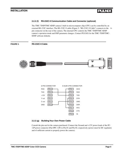
2.2.2 (f) RS-232C-9 Communication Cable and Connector (optional)<br />
The <strong>TMC</strong>-<strong>7DSP</strong>/<strong>TMC</strong>-<strong>6DSP</strong> camera’s built-in microcomputer chip (CPU) can be controlled by an<br />
external RS-232C interface. The RS-232C-9 cable (Figure 5, “RS-232C-9 Cable”) connects to the 6-<br />
pin connector on the rear of the camera. The internal CPU controls the <strong>TMC</strong>-<strong>7DSP</strong>/<strong>TMC</strong>-<strong>6DSP</strong><br />
camera’s operation mode and DSP parameter changes. Contact PULNiX for the <strong>TMC</strong>-<strong>7DSP</strong>/<strong>TMC</strong>-<br />
<strong>6DSP</strong> software diskette.<br />
FIGURE 5.<br />
RS-232C-9 Cable<br />
6-PIN CONNECTOR<br />
D-SUB 9-PIN CONNECTOR<br />
RXD PIN 2 PIN 1 DCD<br />
TXD PIN 2 PIN 2 RXD<br />
+12V PIN 3 PIN 3 TXD<br />
Y out PIN 4 PIN 4 DTR<br />
C out PIN 5 PIN 5 GND<br />
GND PIN 6 PIN 6 DSR<br />
PIN 7<br />
PIN 8<br />
PIN 9<br />
RTS<br />
CTS<br />
RI<br />
2.2.2 (g) Building Your Own Power Cable<br />
Consult the pin-out for the camera purchased. Connect the Ground and +12V power leads of the PC-<br />
12P power connector (Part #PC-12P) to Pin #1 and Pin #2, respectively (power must be DC regulated,<br />
and of sufficient current to properly power the camera).<br />
<strong>TMC</strong>-<strong>7DSP</strong>/<strong>TMC</strong>-<strong>6DSP</strong> <strong>Color</strong> <strong>CCD</strong> <strong>Camera</strong> Page 9