User manual (PDF) - JAI Pulnix
User manual (PDF) - JAI Pulnix
User manual (PDF) - JAI Pulnix

You also want an ePaper? Increase the reach of your titles
YUMPU automatically turns print PDFs into web optimized ePapers that Google loves.
Notice<br />
i<br />
Notice Page<br />
The material contained in this <strong>manual</strong> consists of information that is proprietary to PULNiX America, Inc., and may only be<br />
used by the purchasers of the product. PULNiX America, Inc. makes no warranty for the use of its product and assumes no<br />
responsibility for any errors which may appear or for damages resulting from the use of the information contained herein.<br />
PULNiX America, Inc. reserves the right to make changes without notice.<br />
Microsoft, Windows 98, Windows 95, Windows NT, and Windows Explorer are either registered trademarks or trademarks of<br />
Microsoft Corporation in the United States and/or other countries.<br />
Warranty<br />
All of our solid-state cameras have a full three-year warranty. If any such product proves defective during this warranty<br />
period, PULNiX America, Inc. will repair the defective product without charge for parts and labor or will provide a replacement<br />
in exchange for the defective product. This warranty shall not apply to any damage, defect or failure caused by improper<br />
use or inadequate maintenance.<br />
Certifications<br />
CE Compliance<br />
The TM-6300 camera has been certified to conform to the requirements of Council Directive 89/336/EEC for electromagnetic<br />
compatibility and to comply with the following European Standards:<br />
Immunity:<br />
Emissions:<br />
EN50082-2/1997<br />
CISPR22: 1997/EN55011: 1998 Class B<br />
All PULNiX products bearing the CE mark have been declared to be in conformance with the applicable EEC Council Directives.<br />
However, certain factory-installed options or customer-requested modifications may compromise electromagnetic compatibility<br />
and affect CE compliance. Please note that the use of interconnect cables that are not properly grounded and shielded<br />
may affect CE compliance.<br />
Contact PULNiX Applications Engineering Department for further information regarding CE compliance.<br />
FCC<br />
This equipment has been tested and found to comply with the limits for a Class A digital device, pursuant to Part 15 of the<br />
FCC Rules. These limits are designed to provide reasonable protection against harmful interference when the equipment is<br />
operated in a commercial environment. This equipment generates, uses and can radiate radio frequency energy and, if not<br />
installed and used in accordance with the instruction <strong>manual</strong>, may cause harmful interference to radio communications. Operation<br />
of this equipment in a residential area may cause harmful interference, in which case the user will be required to correct<br />
the interference at his own expense.<br />
WARNING<br />
Changes or modifications to this unit not expressly approved by the party responsible for<br />
FCC compliance could void the user’s authority to operate the equipment.<br />
TM-6300 Operation Manual<br />
PULNiX America, Inc.<br />
1330 Orleans Drive<br />
Sunnyvale, CA 94089<br />
Tel:(408) 747-0300<br />
Tel:(800) 445-5444<br />
Fax:(408) 747-0880<br />
E-mail: imaging@pulnix.com<br />
www.pulnix.com<br />
AUTOMATED<br />
IMAGING<br />
MEMBER<br />
ASSOCIATION<br />
U L<br />
FIR M<br />
®<br />
RE GISTERED<br />
PULNiX AMERICA, INC.<br />
REGISTERED TO ISO-9001<br />
FILE #A3942<br />
TM-6300 Progressive Scan Full Frame Shutter Camera
ii<br />
Table of Contents<br />
1 Introduction . . . . . . . . . . . . . . . . . . . . . . . . . . . . . . . . . . . . .1<br />
1.1 Product Description . . . . . . . . . . . . . . . . . . . . . . . . . . . . . . . . . .1<br />
1.2 Features . . . . . . . . . . . . . . . . . . . . . . . . . . . . . . . . . . . . . . . . . . . .1<br />
1.3 Applications . . . . . . . . . . . . . . . . . . . . . . . . . . . . . . . . . . . . . . . . .3<br />
1.4 System Configuration . . . . . . . . . . . . . . . . . . . . . . . . . . . . . . . . .3<br />
2 Installation . . . . . . . . . . . . . . . . . . . . . . . . . . . . . . . . . . . . . .4<br />
2.1 Getting Started . . . . . . . . . . . . . . . . . . . . . . . . . . . . . . . . . . . . . .4<br />
2.1.1 Unpacking Instructions. . . . . . . . . . . . . . . . . . . . . . . . . . . . . . . . . . . . . 4<br />
2.1.2 Components List . . . . . . . . . . . . . . . . . . . . . . . . . . . . . . . . . . . . . . . . . 4<br />
2.1.3 Accessories . . . . . . . . . . . . . . . . . . . . . . . . . . . . . . . . . . . . . . . . . . . . . 4<br />
2.2 Camera Setup . . . . . . . . . . . . . . . . . . . . . . . . . . . . . . . . . . . . . . .5<br />
2.2.1 Connector Pin Configurations. . . . . . . . . . . . . . . . . . . . . . . . . . . . . . . 5<br />
2.2.2 Rear Panel . . . . . . . . . . . . . . . . . . . . . . . . . . . . . . . . . . . . . . . . . . . . . . 5<br />
2.2.3 Power Supply and Power Cable Setup. . . . . . . . . . . . . . . . . . . . . . . . . 6<br />
2.2.4 Attaching the Video Output. . . . . . . . . . . . . . . . . . . . . . . . . . . . . . . . . 8<br />
2.2.5 Attaching the Camera Lens . . . . . . . . . . . . . . . . . . . . . . . . . . . . . . . . . 8<br />
2.2.6 Auto Iris Lens Setup. . . . . . . . . . . . . . . . . . . . . . . . . . . . . . . . . . . . . . . 8<br />
3 Operation . . . . . . . . . . . . . . . . . . . . . . . . . . . . . . . . . . . . . .9<br />
3.0.1 Progressive Scanning . . . . . . . . . . . . . . . . . . . . . . . . . . . . . . . . . . . . . . 9<br />
3.1 Modes of Operation . . . . . . . . . . . . . . . . . . . . . . . . . . . . . . . . . .9<br />
3.1.1 Asynchronous Reset with Internal Shutter Control . . . . . . . . . . . . . 11<br />
3.1.2 Async Pulse Width Shutter Control . . . . . . . . . . . . . . . . . . . . . . . . . 11<br />
3.1.3 Asynchronous Reset at 0 Shutter . . . . . . . . . . . . . . . . . . . . . . . . . . . 12<br />
3.1.4 External Sync and VINIT Signals. . . . . . . . . . . . . . . . . . . . . . . . . . . . . 12<br />
3.1.5 Gain Control . . . . . . . . . . . . . . . . . . . . . . . . . . . . . . . . . . . . . . . . . . . 13<br />
4 Troubleshooting . . . . . . . . . . . . . . . . . . . . . . . . . . . . . . . . .15<br />
4.1 Problems and Solutions . . . . . . . . . . . . . . . . . . . . . . . . . . . . . . .15<br />
4.1.1 Symptom: No Video . . . . . . . . . . . . . . . . . . . . . . . . . . . . . . . . . . . . . . 15<br />
4.1.2 Symptom: Dark Video. . . . . . . . . . . . . . . . . . . . . . . . . . . . . . . . . . . . . 15<br />
4.1.3 Symptom: Non-synchronized Video. . . . . . . . . . . . . . . . . . . . . . . . . . 15<br />
5 Appendix . . . . . . . . . . . . . . . . . . . . . . . . . . . . . . . . . . . . . .16<br />
5.1 Specifications . . . . . . . . . . . . . . . . . . . . . . . . . . . . . . . . . . . . . . .16<br />
5.1.1 Product Specifications . . . . . . . . . . . . . . . . . . . . . . . . . . . . . . . . . . . . 16<br />
5.1.2 Physical Dimensions . . . . . . . . . . . . . . . . . . . . . . . . . . . . . . . . . . . . . . 17<br />
5.2 Block Diagram . . . . . . . . . . . . . . . . . . . . . . . . . . . . . . . . . . . . . .17<br />
5.3 Information and Support Resources . . . . . . . . . . . . . . . . . . . . .18<br />
TM-6300 Progressive Scan Full Frame Shutter Camera
iii<br />
List of Figures<br />
FIGURE 1. TM-6300 System Configuration . . . . . . . . . . . . . . . . . . . . . . . . . . . . . . . . . . .3<br />
FIGURE 2. TM-6300 Rear Panel . . . . . . . . . . . . . . . . . . . . . . . . . . . . . . . . . . . . . . . . . . . .6<br />
FIGURE 3. 12P-02S Interface Cable (optional). . . . . . . . . . . . . . . . . . . . . . . . . . . . . . . . .7<br />
FIGURE 4. Sync Mode Selection . . . . . . . . . . . . . . . . . . . . . . . . . . . . . . . . . . . . . . . . . . . .9<br />
FIGURE 5. Mode Selection Switch (DIP Switch) . . . . . . . . . . . . . . . . . . . . . . . . . . . . . .10<br />
FIGURE 6. Input Signal Impedance Selection . . . . . . . . . . . . . . . . . . . . . . . . . . . . . . . . .11<br />
FIGURE 7. VINIT (Vertical Initialization) Trigger Specification. . . . . . . . . . . . . . . . . . . .12<br />
FIGURE 8. Equivalent Circuit . . . . . . . . . . . . . . . . . . . . . . . . . . . . . . . . . . . . . . . . . . . . .12<br />
FIGURE 9. Asynchronous Reset at 0 Shutter. . . . . . . . . . . . . . . . . . . . . . . . . . . . . . . . .12<br />
FIGURE 10. Vertical Reset Timing Diagram . . . . . . . . . . . . . . . . . . . . . . . . . . . . . . . . . . .13<br />
FIGURE 11. External Input Signals . . . . . . . . . . . . . . . . . . . . . . . . . . . . . . . . . . . . . . . . . .13<br />
FIGURE 12. Physical Dimensions . . . . . . . . . . . . . . . . . . . . . . . . . . . . . . . . . . . . . . . . . . .18<br />
FIGURE 13. TM-6300 Block Diagram. . . . . . . . . . . . . . . . . . . . . . . . . . . . . . . . . . . . . . . .18<br />
TM-6300 Progressive Scan Full Frame Shutter Camera
iv<br />
List of Tables<br />
TABLE 1. 12-Pin Connector Assignments. . . . . . . . . . . . . . . . . . . . . . . . . . . . . . . . . . . 5<br />
TABLE 2. Mode Selection Switch Settings . . . . . . . . . . . . . . . . . . . . . . . . . . . . . . . . . 10<br />
TABLE 3. Shutter Speed Setting . . . . . . . . . . . . . . . . . . . . . . . . . . . . . . . . . . . . . . . . . 10<br />
TABLE 4. Product Specifications Table . . . . . . . . . . . . . . . . . . . . . . . . . . . . . . . . . . . . 16<br />
TM-1320-15/15CL Progressive Scan Shutter Camera
v<br />
List of Tables<br />
TM-6300 Progressive Scan Full Frame Shutter Camera
March 8, 2002<br />
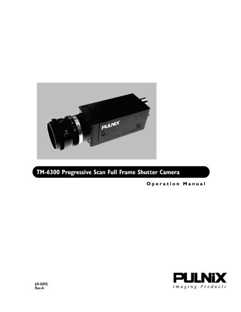
TM-6300 Progressive Scan Full<br />
Frame Shutter Camera<br />
Operation Manual<br />
1 Introduction<br />
1.1 Product Description<br />
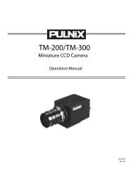
The TM-6300 is a high-performance progressive scan camera with a state-of-the-art 1/3" interline<br />
transfer CCD imager for high-resolution imaging. Double-speed scan, asynchronous reset and<br />
electronic shutter, and non-interlace 60 Hz analog video (VGA) are just some of the features of this<br />
highly functional, compact CCD camera.<br />
This camera offers solutions to a wide variety of application requirements, such as high-speed image<br />
capturing, machine vision, computer graphics, gauging, avionics, microscopy, character and fine<br />
pattern recognition, document reading and high-end surveillance.<br />
1.2 Features<br />
• 1/3" progressive scan interline transfer CCD<br />
The advantages of this CCD are:<br />
- 648H x 484V active pixels for very high resolution and superior image quality<br />
- Square pixels (7.4 x 7.4 µm for precise dimensional measurement)<br />
- Double-speed scan mode: selectable 60Hz VGA and 30Hz normal speed scan<br />
- High-speed electronic shutter capability results in high dynamic resolution of moving<br />
objects<br />
- Progressive scanning eliminates interlace image deterioration<br />
- High sensitivity and low noise at fast scanning, excellent S/N ratio (>50db)<br />
TM-6300 Progressive Scan Full Frame Shutter Camera
Page 2<br />
Introduction<br />
• Asynchronous reset<br />
The TM-6300 resets with an external reset pulse (VINIT). This feature is especially important for<br />
capturing moving objects at a precise location in the field of view, for applications such as a<br />
conveyer belt process, fast event observation, and still picture capturing.<br />
• Integration<br />
The TM-6300 is capable of capturing high-resolution integration images. Integration can last from<br />
1/60 sec. to several seconds.<br />
• VGA display output<br />
The TM-6300 has VGA output which scans out at 60Hz non-interlace. PULNiX PVM-1200 series<br />
monitors or equivalent B/W multi-sync monitors can display the non-interlace images. Please<br />
contact your PULNiX representative for display monitor information.<br />
• Three-Year Warranty<br />
The CCD solid state image sensor allows the camera to maintain a superior performance level<br />
indefinitely while requiring virtually no maintenance. PULNiX backs all of the TM Series cameras<br />
with a three-year warranty.<br />
WARNING: Unscrewing the camera cover or opening the camera in any<br />
way will void this warranty.<br />
TM-6300 Progressive Scan Full Frame Shutter Camera
Page 3<br />
Introduction<br />
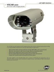
1.3 Applications<br />
Designed for speed and functional versatility, the TM-6300 is ideal for applications such as high-speed<br />
image capturing, machine vision, computer graphics, gauging, avionics, microscopy, character and fine<br />
pattern recognition, document reading and high-end surveillance.<br />
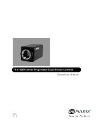
1.4 System Configuration<br />
Figure 1 below presents a typical configuration for the TM-6300 camera.<br />
FIGURE 1. TM-6300 System Configuration<br />
Power<br />
External Sync<br />
Integration<br />
Video Output*<br />
* Video Output is the<br />
same as BNC connector<br />
GAIN<br />
VIDEO<br />
DC IN<br />
MANU<br />
FIX<br />
Computer with<br />
Frame Grabber<br />
Board<br />
(if required)<br />
PULNiX Multi-Sync<br />
Monitor<br />
(PVM-1242 or PVM-942)<br />
NOTE: Additional cable interface may be required from the frame grabber board<br />
manufacturer.<br />
TM-6300 Progressive Scan Full Frame Shutter Camera
Page 4<br />
Installation<br />
2 Installation<br />
The following instructions are provided to help you to set up your video camera system quickly and<br />
easily. We suggest that you read through these instructions prior to unpacking and setting up your<br />
camera system.<br />
2.1 Getting Started<br />
2.1.1 Unpacking Instructions<br />
We recommend that you save the original packing cartons for the cameras and lenses in case you need<br />
to return or exchange an item.<br />
We also recommend that any equipment being sent to another location for field installation be bench<br />
tested to assure that everything is fully operational as a system.<br />
2.1.2 Components List<br />
Please begin by checking your order against the Components List (below) to assure that you have<br />
received everything as ordered, and that nothing has been overlooked in the packing materials. If any<br />
item is missing, please contact your PULNiX representative immediately.<br />
• TM-6300 camera<br />
• TM-6300 data sheet<br />
• TM-6300 <strong>manual</strong> (by request)<br />
2.1.3 Accessories<br />
Following is a list of additional accessories or equipment that may be recommended or required for your<br />
particular application. Please check with your PULNiX representative prior to the installation of your<br />
video system to determine what you might need.<br />
• Cable (power/video) 12P-02S<br />
• PVM-1242 or PVM-942 multi-sync monitor<br />
• Power supply PD-12UU or PD-12UUP<br />
TM-6300 Progressive Scan Full Frame Shutter Camera
Page 5<br />
Installation<br />
2.2 Camera Setup<br />
2.2.1 Connector Pin Configurations<br />
2.2.1 (a) 12-Pin Connector<br />
The TM-6300 has a 12-pin connector for power input. Pin #1 is Ground and Pin<br />
#2 is +12V DC. The other pins handle a number of other input and output<br />
functions as detailed below.<br />
Note:<br />
Internal-Sync and External-Sync modes are selected by an internal<br />
switch. If external HD is not present, the camera operates in Internal-<br />
Sync mode.<br />
3<br />
2<br />
4<br />
1 9<br />
10<br />
11 12<br />
5<br />
8<br />
6<br />
7<br />
TABLE 1.<br />
Refer to Section 3 on page 9 for selection.<br />
12-Pin Connector Assignments<br />
Internal<br />
External Sync Mode<br />
Pin No. Sync Mode HD/VD HD/VINIT<br />
1 GND GND GND<br />
2 +12V +12V +12V<br />
3 GND GND GND<br />
4 Video out Video out Video out<br />
5 GND GND GND<br />
6 HD out HD in HD in<br />
7 VD out VD in —<br />
8 GND GND GND<br />
9 — — —<br />
10 GND GND GND<br />
11 — — VINIT<br />
12 GND GND GND<br />
2.2.2 Rear Panel<br />
Functions and controls located on the camera rear panel:<br />
FIGURE 2.<br />
TM-6300 Rear Panel<br />
GAIN<br />
VIDEO<br />
• 12-pin connector (power, I/Os)<br />
• BNC video cable connector<br />
DC IN<br />
• Manual gain control adjustment<br />
MANU<br />
FIX<br />
• Manual/Fix Gain switch<br />
TM-6300 Progressive Scan Full Frame Shutter Camera
Page 6<br />
Installation<br />
2.2.3 Power Supply and Power Cable Setup<br />
2.2.3 (a) Power Supplies<br />
PULNiX recommends the following power supplies:<br />
K25-12V 110V AC/12V DC 2.1A power supply (requires 12P-02S power cable)<br />
K50-12V 110V AC/12V DC 4.2A power supply (requires 12P-02S power cable)<br />
PD-12UU 100-240V AC/12V DC 1.2A universal voltage power supply with US plug<br />
PD-12UUP 100-240V 1.2A universal voltage power supply with US plug<br />
and 12-pin connector<br />
PD-12UE 100-240V/12V DC 1.2A universal power supply with European plug<br />
PD-12UEP PD-12UU with 12-pin 1.2A universal power supply with European plug<br />
connector<br />
and 12-pin connector<br />
If you are providing power through the 12-pin connector, the PD-12UUP and PD-12UEP power<br />
supplies are available with the 12-pin mating connector already attached to the leads from the power<br />
supply. The PD-12UU or PD-12UE power supply can be connected to the PULNiX power cable via a<br />
terminal strip or directly.<br />
If wiring the PD-12UU power supply directly, please note the following:<br />
• Twist the lead ends together and tin solder for strength and electrical continuity<br />
• Use shrink tubing or a similar insulator to prevent exposed leads from touching<br />
• The +12V lead is marked with a red stripe or white lettering; be sure not to reverse the leads<br />
• Properly insulate all connections to prevent shorting<br />
2.2.3 (b) Using PULNiX Power/Video Cables<br />
If you are using PULNiX power cables, such as the 12P-02S, etc., please refer to the pin-out diagram.<br />
The color-coded leads use Gray for Ground and Yellow for +12V DC. Refer to Figure 3.<br />
TM-6300 Progressive Scan Full Frame Shutter Camera
Page 7<br />
Installation<br />
FIGURE 3.<br />
12P-02S Interface Cable (optional)<br />
1 32mm<br />
Flying<br />
Leads<br />
1 PC-12P(Hirose Part #10A-10P-12S /PC12P)<br />
2,000mm± 10mm<br />
(2 Meters)<br />
NOTE: Make sure that the unused leads are not touching and that there is no possibility that<br />
the leads could short due to exposed wires.<br />
2.2.3 (c) Using the “K” Series Power Supplies<br />
Attach the 110V line cord to the two terminals marked “AC”. Do not plug the cord into a 110V AC<br />
socket until later in the procedure. Next, attach the Gray and Yellow leads of the power cable to the<br />
Ground and 12V DC terminals respectively. Be sure to replace the plastic terminal guard on the power<br />
supply at this time.<br />
NOTE: The “K” series power supplies are designed primarily for OEM users who will be<br />
mounting the power supply inside a protective enclosure. For use in exposed<br />
situations, the PD-12UU is recommended.<br />
2.2.3 (d) Building Your Own Power Cables<br />
12P-02S Interface Cable<br />
Pin# Lead Color Function Pin# Lead Color Function<br />
1 Gray GND 7 Black coax VD Input<br />
2 Yellow +12VCD 8 White coax shield GND<br />
3 Red coax shield GND 9 White coax —<br />
4 Red coax Video 10 Brown GND<br />
5 Orange coax shield GND 11 Blue VINIT<br />
6 Orange coax HD 12 Black coax shield GND<br />
If you are building your own power cables, consult the pin-out for the camera purchased and connect<br />
the Ground and +12V power leads of the PC-12P power connector to Pin #1 and Pin #2, respectively<br />
(power must be DC regulated, and of sufficient current to properly power the camera).<br />
2.2.3 (e) Attaching the Power Cable to the Connector<br />
The 12-pin connector is keyed and will only fit in one orientation. Rotate the connector while applying<br />
slight pressure until the keyways line up. Press the connector into place until firmly seated.<br />
The power cord may now be plugged into the 100V AC socket, and the camera powered up.<br />
TM-6300 Progressive Scan Full Frame Shutter Camera
Page 8<br />
Installation<br />
2.2.4 Attaching the Video Output<br />
Most users utilize the BNC connector for video output from the camera. Connect the output from the<br />
camera to the input of your monitor, VCR or switching device. The input of the monitor should be<br />
balanced for 75Ω termination. Standard RG-59 type coaxial cable should carry a full video signal for up<br />
to 500 feet.<br />
<strong>User</strong>s wishing to output the video and input the power and sync to a camera over a single cable can use<br />
PULNiX multi-conductor cables, such as the 12P-02S, etc. The mini coaxial leads in PULNiX multiconductor<br />
cables are designed for short runs of no longer than 100 feet.<br />
NOTE: Make sure that no extraneous wires are visible which could cause a short.<br />
2.2.5 Attaching the Camera Lens<br />
The TM-6300 camera accepts standard C-mount lenses. To attach the C-mount lens to the camera,<br />
carefully engage the threads and rotate the lens clockwise until it firmly seats on the mounting ring. Do<br />
not force the lens if it does not seat properly. Please note that some lenses with extremely long<br />
flangebacks may exceed the mounting depth of the camera.<br />
2.2.6 Auto Iris Lens Setup<br />
Auto-iris lenses with full video input can be used with the PULNiX TM-6300, although this camera<br />
model does not come equipped with auto-iris output.<br />
NOTE: Make sure that the power is removed from the camera before connecting or<br />
disconnecting the auto-iris lens. There is a small chance that damage could occur to<br />
the auto-iris lens by plugging or unplugging it while the camera is powered up.<br />
To install the auto-iris lens in a PULNiX camera for which the auto-iris output is not supplied, wire the<br />
signal (video) on the lens into the terminal 1 Vp-p video output on the camera (pin 4 of 12 pin<br />
connector).<br />
Point the camera at a light area and then quickly towards a darker area. If everything is working<br />
properly, the iris should adjust for the light change.<br />
TM-6300 Progressive Scan Full Frame Shutter Camera
Page 9<br />
Operation<br />
3 Operation<br />
3.0.1 Progressive Scanning<br />
The TM-6300 uses a state-of-the-art CCD called a “Progressive scanning interline transfer CCD” which<br />
scans all lines sequentially from top to bottom at one frame rate (60 Hz). Like a non-interlace computer<br />
screen, it generates a stable crisp image without alternating lines, as well as providing full vertical TV<br />
resolution of 484 lines. The interline transfer architecture is also important to generate simultaneous<br />
shuttering. This is different from full frame transfer architecture which requires a mechanical shutter or<br />
strobe light in order to freeze the object motion.<br />
The TM-6300 outputs the progressive scanned image with an electronic shutter in two standard and one<br />
optional format:<br />
1. Progressive scanning double speed output<br />
This produces straightforward signal output equivalent to non-interlace VGA format (60Hz). Realtime<br />
double-speed CCD output is converted through normal analog video processing into 75Ω<br />
1Vp-p output format.<br />
2. Progressive scanning 30Hz output<br />
The TM-6300 scanning clock is reduced to half of normal speed so that the frame rate is 30Hz. All<br />
other functions, such as Hd, VD, pixel clock and external sync, are also twice that of normal speed.<br />
3.1 Modes of Operation<br />
The TM-6300 is designed to accommodate a high resolution, on-line inspection reset mechanism with<br />
full frame shutter. It accepts external horizontal sync (HD, TTL Levels) to lock the camera and VINIT<br />
pulse for resetting the camera asynchronously. Refer to Figure 4, Figure 5, and Figure 6. HD is not<br />
required for asynchronous reset of the camera. The shutter speed is set by the internal top board DIP<br />
switch, positions 5 to 9. Refer to Table 3.<br />
FIGURE 4.<br />
Sync Mode Selection<br />
Internal<br />
External<br />
Sync selection switch<br />
FIGURE 5.<br />
Mode Selection Switch (DIP Switch)<br />
ON<br />
ON<br />
1<br />
2<br />
3<br />
4<br />
5<br />
6<br />
7<br />
8<br />
9<br />
10<br />
OFF<br />
TM-6300 Progressive Scan Full Frame Shutter Camera
Page 10<br />
Operation<br />
TABLE 2.<br />
Mode Selection Switch Settings<br />
Switch Number<br />
Function Description 1 2 3 4 5-9 10<br />
2:1 interlace-scan 60 field/s OFF OFF<br />
2:1 interlace-scan 30 field/s OFF ON<br />
Progressive scan 60 frame/s ON OFF<br />
Progressive scan 30 frame/s ON ON<br />
External Shutter Control<br />
OFF not used OFF<br />
mode single pulse (width)<br />
External Shutter Control<br />
OFF not used ON<br />
mode double pulse (width)<br />
Internal shutter control mode ON table 3 X<br />
AGC (Auto Gain Control)<br />
OFF<br />
MGC (Manual Gain Control<br />
ON<br />
TABLE 3.<br />
Shutter Speed Setting<br />
Switch number<br />
5 6 7 8 9<br />
Shutter speed<br />
30 fps 60 fps<br />
OFF OFF OFF OFF OFF no shutter<br />
ON ON OFF OFF OFF 1/100 1/200<br />
ON OFF ON OFF OFF 1/125 1/250<br />
ON OFF OFF ON OFF 1/250 1/500<br />
ON OFF ON ON OFF 1/500 1/1000<br />
ON OFF OFF OFF ON 1/1000 1/2000<br />
ON OFF ON OFF ON 1/2000 1/4000<br />
ON OFF OFF ON ON 1/4000 1/8000<br />
ON OFF ON ON ON 1/10000 1/20000<br />
FIGURE 6.<br />
Input Signal Impedance Selection<br />
up: 75Ω<br />
down: high impedance<br />
Up position is 75 Ω for HD and VD inputs.<br />
TM-6300 Progressive Scan Full Frame Shutter Camera
Page 11<br />
Operation<br />
Down position is high impedance. When VINIT is used for async pulse width shutter control, the input<br />
impedance selection must be “high impedance” position.<br />
3.1.1 Asynchronous Reset with Internal Shutter Control<br />
Select DIP switch #2 to OFF to select Internal Shutter Control mode.<br />
The TM-6300's asynchronous reset is flexible and takes external HD for phase locking (if required).<br />
Applying a VINIT pulse resets the camera's scanning and purging of the CCD. Do not supply VD if the<br />
asynchronous reset is used. Instead, use HD to synchronize the camera to the external device.<br />
When external VINIT is high (5V), the TM-6300 expects the async pulse input, and the video output<br />
will be black video. It resets at the negative going pulse edge and captures the frame regardless of the<br />
shutter speed (fast or slow mode). The video output is kept disabled as the CCD is discharged<br />
continuously during VINIT high. When the first VINIT pulse comes in, it resets the timing and outputs<br />
the image. If the switch is set to NRM (normal mode), the video output will be real time with <strong>manual</strong><br />
shutter.<br />
3.1.2 Async Pulse Width Shutter Control<br />
A VINIT pulse can control async reset and shutter speed. To select the External Pulse Width Control<br />
mode, set switch #2 to “OFF” position. Apply a pulse width control VINIT signal to the camera via an<br />
external event trigger. Refer to Figure 7 and Figure 8. The leading edge (negative going edge) resets<br />
camera and the pulse width (between falling edge and rising edge) controls the shutter speed. At leading<br />
edge of the VINIT pulse, CCD is discharged and start integrating. At the trailing edge of the pulse, it<br />
transfers the charges to vertical shift registers to output the image. This async operation can be<br />
implemented with or without external HD. However, for majority of applications, we recommend<br />
locking the camera with external HD.<br />
With this mode, video Vsync appears only once per trigger.<br />
FIGURE 7.<br />
VINIT (Vertical Initialization) Trigger Specification<br />
Async Reset<br />
Exposure<br />
Time<br />
End of Integration<br />
Discharge<br />
Video<br />
Delay (1H max)<br />
4H<br />
V sync (3H)<br />
29H<br />
Video<br />
1H = 32 µsec (60 fps), 64 µsec (30 fps)<br />
TM-6300 Progressive Scan Full Frame Shutter Camera
Page 12<br />
Operation<br />
FIGURE 8.<br />
Equivalent Circuit<br />
VINIT<br />
10K<br />
3.1.3 Asynchronous Reset at 0 Shutter<br />
This resets the camera without shutter function. This is useful for conventional strobe applications.<br />
FIGURE 9.<br />
Asynchronous Reset at 0 Shutter<br />
VINIT<br />
ASYNC RESET<br />
VD<br />
SG (TRANSFER GATE)<br />
PROGRESSIVE OUTPUT<br />
VIDEO<br />
Stand-by Image Shutter Video<br />
Stand-by Image<br />
3.1.3 (a) Vertical Reset Mode<br />
With external HD, VD reset mode, single VD can be applied at random timing (async timing) to<br />
generate single shot video output. In progressive scan mode, it outputs one full frame image and in<br />
interlace scan mode, it outputs one field image (ODD or EVEN field depending on VD and HD timing<br />
relationship).<br />
FIGURE 10. Vertical Reset Timing Diagram<br />
HD<br />
Ext. VD<br />
Internal VD<br />
Video<br />
TM-6300 Progressive Scan Full Frame Shutter Camera
Page 13<br />
Operation<br />
3.1.4 External Sync and VINIT Signals<br />
Refer to Figure 11.<br />
External sync— HD and VD signal level is TTL, negative going pulse. It must be 2.0 V to 5.0 V for<br />
high level to both high impedance or 75Ω drive.<br />
HD frequency requirement for PLL is 31.468 KHz ±5% for 60 fps and 15.734 KHz ±5% for 30 fps.<br />
VD is 59.94 Hz ±5% for 60 fps reset and 29.97 ±5% for 30 fps reset.<br />
Async pulse width shutter control— VINIT trigger is high-impedance input. The high level is 4V to<br />
5V TTL<br />
FIGURE 11. External Input Signals<br />
1/HD frequency<br />
+5Volts<br />
HD<br />
TTL Level<br />
0 Volts<br />
1 - 2µsec.<br />
+5Volts<br />
VD<br />
1/VD frequency<br />
0 Volts<br />
TTL Level<br />
1 to 9H<br />
3.1.5 Gain Control<br />
GAIN<br />
VIDEO<br />
DC IN<br />
MANU<br />
FIX<br />
Fixed gain is factory set at 17 dB.<br />
Manual gain is variable from 6 dB to 25 dB.<br />
Automatic gain control (AGC) is selected by DIP SW #4.<br />
TM-6300 Progressive Scan Full Frame Shutter Camera
Page 14<br />
Operation<br />
3.1.5 (a) Gamma Selection<br />
Set the Gamma selection switch to the desired Gamma setting.<br />
Gamma selection switch<br />
Gamma = 0.45<br />
Gamma = 1<br />
TM-6300 Progressive Scan Full Frame Shutter Camera
Page 15<br />
Troubleshooting<br />
4 Troubleshooting<br />
4.1 Problems and Solutions<br />
Following are troubleshooting tips for common problems. Generally, problems can be easily solved by<br />
following these instructions. If the following remedies fail to offer a solution to your problems, please<br />
contact a PULNiX representative.<br />
4.1.1 Symptom: No Video<br />
Remedies: Check that the following are properly connected and operational.<br />
• Power supplies<br />
• Power cables<br />
• Main power source<br />
• Shutter control<br />
• Async mode<br />
• Lens<br />
4.1.2 Symptom: Dark Video<br />
Remedies: Check that the following are properly connected and operational.<br />
• Shutter selection<br />
• Iris opening on the lens<br />
• Async mode with 5 volt level on “VINIT” (Pin #11)<br />
4.1.3 Symptom: Non-synchronized Video<br />
Remedies: Check that the following are properly connected and operational.<br />
• Proper mode output<br />
• Frame grabber software camera selection<br />
TM-6300 Progressive Scan Full Frame Shutter Camera
Page 16<br />
Appendix<br />
5 Appendix<br />
5.1 Specifications<br />
TABLE 4.<br />
5.1.1 Product Specifications<br />
Product Specifications Table<br />
Image Sensor<br />
Pixels<br />
Cell Size<br />
Scanning<br />
Scanning Area<br />
Sync<br />
Asynchronous Reset<br />
Pixel clock<br />
Resolution<br />
S/N ratio<br />
Minimum illumination<br />
Video output<br />
AGC<br />
Gamma<br />
Electronic shutter<br />
1/3” Progressive interline transfer CCD<br />
659 (H) x 494 (V)<br />
7.4µm x 7.4µm square pixels<br />
30 or 60 frames/sec. with single channel output (VGA output)<br />
4.88 mm (H) x 3.66 mm (V)<br />
Internal/external auto switch<br />
HD=31.468 KHz, (15.734 KHz) ±5%<br />
Vertical async reset or VD=60 or 30 Hz<br />
(non-interlace)<br />
Ext. Vinit (Trigger) for async reset<br />
24.5454 MHz or 12.2727 MHz<br />
500 (H) x 494 (V) TV lines<br />
56dB min (at 30fps)<br />
1 Lux at 30 fps, 2 Lux at 60 fps, F=1.4<br />
1.0 Vp-p composite, 75Ω non-interlace<br />
Manual/Factory preset/AGC switchable<br />
0.45 or 1.0 (standard)<br />
Asynchronous electronic shutter (60fps or 30 fps)<br />
Mode A: 1/120,000 or 1/110,000 Max (<strong>manual</strong> speed)<br />
Mode B: Async pulse width control<br />
(500/100 µsec to 8.3/16.7 µsec)<br />
Full frame resolution per shutter<br />
Lens mount<br />
C-mount<br />
Power requirements<br />
12V DC, 210 mA<br />
Operating temperature -10°C to 50°C<br />
Vibration, Random<br />
7Grms 10-2000 Hz<br />
Shock<br />
70G 10-11 msec<br />
Size (W x H x L)<br />
31.2mm (W) x 29.1mm (H) x 72.7mm (L)<br />
(1.23” x 1.15” x 2.86”)<br />
Weight<br />
85 g<br />
Auto Iris Connector<br />
None<br />
Functional Options<br />
I/O accessories<br />
Power cable<br />
Power supply<br />
12P-02S<br />
K25-125 or PD-12UUP<br />
TM-6300 Progressive Scan Full Frame Shutter Camera
Page 17<br />
Appendix<br />
5.1.2 Physical Dimensions<br />
FIGURE 12. Physical Dimensions<br />
2x 26.0 [1.02]<br />
PULNiX<br />
GAIN<br />
DC IN<br />
VIDEO<br />
29.1 [1.15]<br />
MANU<br />
FIX<br />
1" 32 UNC<br />
72.7 [2.86]<br />
85.4 [3.36]<br />
31.2 [1.23]<br />
2x 12.7 [0.50]<br />
56.0 [2.20]<br />
6x M3 x 4.0 [0.16] DEEP<br />
2x 26.0 [1.02]<br />
25.0 [0.98]<br />
32.4 [1.28]<br />
25.0 [0.98]<br />
4x M2 x 3.0 [0.12] DEEP<br />
5.2 Block Diagram<br />
FIGURE 13. TM-6300 Block Diagram<br />
CCD<br />
CDS & AMP<br />
SYNC<br />
ADDED<br />
VIDEO<br />
TIMING<br />
GEN.<br />
SYNC<br />
GEN.<br />
PLL/XTAL<br />
EXT. HD<br />
TM-6300 Progressive Scan Full Frame Shutter Camera
Page 18<br />
Appendix<br />
5.3 Information and Support Resources<br />
For further information and support:<br />
Phone: (408) 747-0300<br />
(800) 445-5444<br />
(800) 3-PULNIX (24-hour message access)<br />
Fax: (408) 747-0660<br />
E-mail:<br />
imaging@pulnix.com<br />
Mail:<br />
PULNiX America Inc.<br />
Sales Department<br />
1330 Orleans Drive<br />
Sunnyvale, CA 94089<br />
ATTN: Video Applications<br />
Web Site:<br />
www.pulnix.com<br />
TM-6300 Progressive Scan Full Frame Shutter Camera