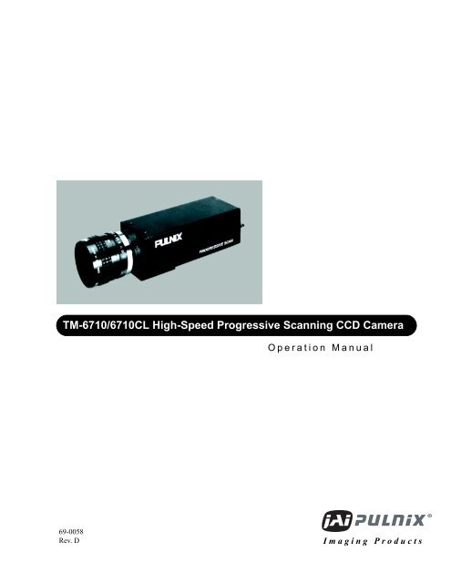
TM-6710/6710CL High-Speed Progressive Scanning ... - JAI Pulnix
TM-6710/6710CL High-Speed Progressive Scanning ... - JAI Pulnix
TM-6710/6710CL High-Speed Progressive Scanning ... - JAI Pulnix

Create successful ePaper yourself
Turn your PDF publications into a flip-book with our unique Google optimized e-Paper software.
<strong>TM</strong>-<strong>6710</strong>/<strong>6710</strong>CL <strong>High</strong>-<strong>Speed</strong> <strong>Progressive</strong> <strong>Scanning</strong> CCD Camera<br />
Operation Manual<br />
69-0058<br />
Rev. D<br />
Imaging Products
i<br />
Notice Page<br />
Notice<br />
The material contained in this manual consists of information that is proprietary to <strong>JAI</strong> PULNiX, Inc., and may only be used<br />
by the purchasers of the product. <strong>JAI</strong> PULNiX, Inc. makes no warranty for the use of its product and assumes no responsibility<br />
for any errors which may appear or for damages resulting from the use of the information contained herein. <strong>JAI</strong> PULNiX, Inc.<br />
reserves the right to make changes without notice.<br />
Warranty<br />
Please contact your factory representative for details about the warranty.<br />
Certifications<br />
CE Compliance<br />
The <strong>TM</strong>-<strong>6710</strong>/<strong>6710</strong>CL has been certified to conform to the requirements of Council Directive 89/336/EC for electromagnetic<br />
compatibility and to comply with the following European Standards:<br />
Immunity: EN500082-2/1995<br />
Emissions: EN55022:1995 Class A / CISPR 22:1993<br />
All PULNiX products bearing the CE mark have been declared to be in conformance with the applicable EEC Council Directives.<br />
However, certain factory installed options or customer requested modifications may compromise electromagnetic compatibility<br />
and prohibit use of the CE mark. Please note that the use of interconnect cables that are not properly grounded and<br />
shielded may affect CE compliance. Contact PULNiX Applications Engineering Department for further information regarding<br />
CE compliance.<br />
FCC<br />
This equipment has been tested and found to comply with the limits for a Class A digital device, pursuant to Part 15 of the<br />
FCC Rules. These limits are designed to provide reasonable protection against harmful interference when the equipment is<br />
operated in a commercial environment. This equipment generates, uses and can radiate radio frequency energy and, if not<br />
installed and used in accordance with the instruction manual, may cause harmful interference to radio communications. Operation<br />
of this equipment in a residential area is likely to cause harmful interference in which case the user will be required to<br />
correct the interference at his own expense.<br />
WARNING<br />
Changes or modifications to this unit not expressly approved by the party responsible for<br />
FCC compliance could void the user’s authority to operate the equipment.<br />
<strong>TM</strong>-<strong>6710</strong>/<strong>6710</strong>CL Operation Manual<br />
Printing: August 30, 2004<br />
<strong>JAI</strong> PULNiX, Inc.<br />
1330 Orleans Drive<br />
Sunnyvale, CA 94089<br />
Tel: (408) 747-0300<br />
Tel: (800) 445-5444<br />
Fax: (408) 747-0880<br />
E-mail: imaging@jaipulnix.com<br />
www.jaipulnix.com<br />
AUTOMATED<br />
IMAGING<br />
MEMBER<br />
FILE #<br />
A3942<br />
U L<br />
FIR M<br />
®<br />
RE GISTERED<br />
ISO-9001<br />
ASSOCIATION<br />
<strong>JAI</strong> PULNiX INC.<br />
<strong>TM</strong>-<strong>6710</strong>/<strong>6710</strong>CL <strong>High</strong>-<strong>Speed</strong> <strong>Progressive</strong> <strong>Scanning</strong> CCD Camera
ii<br />
Table of Contents<br />
1 Introduction . . . . . . . . . . . . . . . . . . . . . . . . . . . . . . . . . . . . 1<br />
1.1 Product Description . . . . . . . . . . . . . . . . . . . . . . . . . . . . . . . . . . 1<br />
1.2 Features. . . . . . . . . . . . . . . . . . . . . . . . . . . . . . . . . . . . . . . . . . . . 1<br />
1.3 Applications . . . . . . . . . . . . . . . . . . . . . . . . . . . . . . . . . . . . . . . . 2<br />
1.4 System Configuration. . . . . . . . . . . . . . . . . . . . . . . . . . . . . . . . . 3<br />
2 Installation . . . . . . . . . . . . . . . . . . . . . . . . . . . . . . . . . . . . . 5<br />
2.1 Getting Started . . . . . . . . . . . . . . . . . . . . . . . . . . . . . . . . . . . . . . 5<br />
2.1.1 Unpacking Instructions. . . . . . . . . . . . . . . . . . . . . . . . . . . . . . . . . . . . . 5<br />
2.1.2 Components List. . . . . . . . . . . . . . . . . . . . . . . . . . . . . . . . . . . . . . . . . . 5<br />
2.1.3 Accessories and Options. . . . . . . . . . . . . . . . . . . . . . . . . . . . . . . . . . . . 5<br />
2.2 Camera Setup . . . . . . . . . . . . . . . . . . . . . . . . . . . . . . . . . . . . . . . 6<br />
2.2.1 Pin Configurations . . . . . . . . . . . . . . . . . . . . . . . . . . . . . . . . . . . . . . . . 6<br />
2.2.2 Power Supply and Power Cable Setup . . . . . . . . . . . . . . . . . . . . . . . . . 8<br />
2.2.3 RS-232 Cables and Connectors (<strong>TM</strong>-<strong>6710</strong> only) . . . . . . . . . . . . . . . . 10<br />
2.2.4 Attaching the Video Output (Analog<br />
Output on <strong>TM</strong>-<strong>6710</strong> Only) . . . . . . . . . . . . . . . . . . . . . . . . . . . . . . . . . 10<br />
2.2.5 Attaching the Camera Lens. . . . . . . . . . . . . . . . . . . . . . . . . . . . . . . . . 11<br />
2.2.6 Back focusing the Lens. . . . . . . . . . . . . . . . . . . . . . . . . . . . . . . . . . . . 11<br />
3 Operation . . . . . . . . . . . . . . . . . . . . . . . . . . . . . . . . . . . . . 12<br />
3.1 Dual-Tap Video Output . . . . . . . . . . . . . . . . . . . . . . . . . . . . . . 12<br />
3.2 Rear Panel. . . . . . . . . . . . . . . . . . . . . . . . . . . . . . . . . . . . . . . . . 12<br />
3.2.1 Mode Control Switches (<strong>TM</strong>-<strong>6710</strong>) . . . . . . . . . . . . . . . . . . . . . . . . . . 14<br />
3.3 Modes of Operation . . . . . . . . . . . . . . . . . . . . . . . . . . . . . . . . . 14<br />
3.3.1 Shutter Operation . . . . . . . . . . . . . . . . . . . . . . . . . . . . . . . . . . . . . . . . 14<br />
3.3.2 External Synchronization . . . . . . . . . . . . . . . . . . . . . . . . . . . . . . . . . . 15<br />
3.3.3 Asynchronous Reset with Shutter. . . . . . . . . . . . . . . . . . . . . . . . . . . . 15<br />
3.3.4 Partial Scan Mode. . . . . . . . . . . . . . . . . . . . . . . . . . . . . . . . . . . . . . . . 18<br />
3.3.5 Integration. . . . . . . . . . . . . . . . . . . . . . . . . . . . . . . . . . . . . . . . . . . . . . 18<br />
3.3.6 <strong>Progressive</strong> scanning . . . . . . . . . . . . . . . . . . . . . . . . . . . . . . . . . . . . . 19<br />
3.3.7 RS-232C (or optional RS-485) Control and Camera<br />
Link Serial Communication. . . . . . . . . . . . . . . . . . . . . . . . . . . . . . . . 19<br />
3.3.8 Video Output. . . . . . . . . . . . . . . . . . . . . . . . . . . . . . . . . . . . . . . . . . . . 25<br />
3.3.9 Timing. . . . . . . . . . . . . . . . . . . . . . . . . . . . . . . . . . . . . . . . . . . . . . . . . 25<br />
4 Camera Timing Charts . . . . . . . . . . . . . . . . . . . . . . . . . . . 27<br />
5 Troubleshooting . . . . . . . . . . . . . . . . . . . . . . . . . . . . . . . . 31<br />
5.1 Problems and Solutions . . . . . . . . . . . . . . . . . . . . . . . . . . . . . . 31<br />
5.1.1 Symptom: No Video . . . . . . . . . . . . . . . . . . . . . . . . . . . . . . . . . . . . . . 31<br />
5.1.2 Symptom: Dark Video . . . . . . . . . . . . . . . . . . . . . . . . . . . . . . . . . . . . 31<br />
5.1.3 Symptom: Non-synchronized Video. . . . . . . . . . . . . . . . . . . . . . . . . . 31<br />
5.1.4 Symptom: RS-232 Non-communication . . . . . . . . . . . . . . . . . . . . . . 31<br />
5.2 Information and Support Resources . . . . . . . . . . . . . . . . . . . . . 32<br />
6 Appendix . . . . . . . . . . . . . . . . . . . . . . . . . . . . . . . . . . . . . 33<br />
6.1 Specifications . . . . . . . . . . . . . . . . . . . . . . . . . . . . . . . . . . . . . . 33<br />
6.2 Block Diagrams . . . . . . . . . . . . . . . . . . . . . . . . . . . . . . . . . . . . 36<br />
<strong>TM</strong>-<strong>6710</strong>/<strong>6710</strong>CL <strong>High</strong>-<strong>Speed</strong> <strong>Progressive</strong> <strong>Scanning</strong> CCD Camera
iii<br />
List of Figures<br />
FIGURE 1. <strong>TM</strong>-<strong>6710</strong> System Configuration . . . . . . . . . . . . . . . . . . . . . . . . . . . . . . . . . . 3<br />
FIGURE 2. <strong>TM</strong>-<strong>6710</strong>CL System Configuration. . . . . . . . . . . . . . . . . . . . . . . . . . . . . . . . 4<br />
FIGURE 3. 51-Pin Connector . . . . . . . . . . . . . . . . . . . . . . . . . . . . . . . . . . . . . . . . . . . . . 7<br />
FIGURE 4. Camera Link Connector. . . . . . . . . . . . . . . . . . . . . . . . . . . . . . . . . . . . . . . . . 7<br />
FIGURE 5. MDR 26-Pin Connector (0226-622VC) . . . . . . . . . . . . . . . . . . . . . . . . . . . . 8<br />
FIGURE 6. 12P-02S Power Cable . . . . . . . . . . . . . . . . . . . . . . . . . . . . . . . . . . . . . . . . . . 9<br />
FIGURE 7. RS-232 Serial Communication Cable . . . . . . . . . . . . . . . . . . . . . . . . . . . . . 10<br />
FIGURE 8. Rear Panel Layout (<strong>TM</strong>-<strong>6710</strong>) . . . . . . . . . . . . . . . . . . . . . . . . . . . . . . . . . . 12<br />
FIGURE 9. Rear Panel Layout (<strong>TM</strong>-<strong>6710</strong>CL) . . . . . . . . . . . . . . . . . . . . . . . . . . . . . . . . 13<br />
FIGURE 10. External Pulse Width Mode. . . . . . . . . . . . . . . . . . . . . . . . . . . . . . . . . . . . . 16<br />
FIGURE 11. Internal Fast Reset Mode. . . . . . . . . . . . . . . . . . . . . . . . . . . . . . . . . . . . . . . 17<br />
FIGURE 12. Internal Slow Reset Mode . . . . . . . . . . . . . . . . . . . . . . . . . . . . . . . . . . . . . . 18<br />
FIGURE 13. Async Reset Image Capture . . . . . . . . . . . . . . . . . . . . . . . . . . . . . . . . . . . . 25<br />
FIGURE 14. Integrated Image Capture . . . . . . . . . . . . . . . . . . . . . . . . . . . . . . . . . . . . . . 25<br />
FIGURE 15. <strong>TM</strong>-<strong>6710</strong> Physical Dimensions . . . . . . . . . . . . . . . . . . . . . . . . . . . . . . . . . . 34<br />
FIGURE 16. <strong>TM</strong>-<strong>6710</strong>CL Physical Dimensions . . . . . . . . . . . . . . . . . . . . . . . . . . . . . . . 34<br />
FIGURE 17. Glass Specifications. . . . . . . . . . . . . . . . . . . . . . . . . . . . . . . . . . . . . . . . . . . 35<br />
FIGURE 18. <strong>TM</strong>-<strong>6710</strong> Spectral Response . . . . . . . . . . . . . . . . . . . . . . . . . . . . . . . . . . . . 35<br />
FIGURE 19. <strong>TM</strong>-<strong>6710</strong> Block Diagram . . . . . . . . . . . . . . . . . . . . . . . . . . . . . . . . . . . . . . 36<br />
FIGURE 20. <strong>TM</strong>-<strong>6710</strong>CL Block Diagram . . . . . . . . . . . . . . . . . . . . . . . . . . . . . . . . . . . . 36<br />
<strong>TM</strong>-<strong>6710</strong>/<strong>6710</strong>CL <strong>High</strong>-<strong>Speed</strong> <strong>Progressive</strong> <strong>Scanning</strong> CCD Camera
August 30, 2004<br />
<strong>TM</strong>-<strong>6710</strong>/<strong>6710</strong>CL <strong>High</strong>-<strong>Speed</strong><br />
<strong>Progressive</strong> <strong>Scanning</strong> CCD Camera<br />
Operation Manual<br />
1 Introduction<br />
1.1 Product Description<br />
The <strong>TM</strong>-<strong>6710</strong> * is a high-resolution monochrome CCD camera with “quad speed” 120FPS dual-tap,<br />
dual-channel digital output.<br />
1.2 Features<br />
• Three scanning modes<br />
- Non-interlace quad speed scanning (484 active lines at 120Hz or 60Hz (selectable))<br />
- 200 lines partial scanning (at 236Hz)<br />
- 100 lines partial scanning (at 300Hz)<br />
• Full frame electronic shutter<br />
The substrate drain electronic shutter captures images at various speeds without any smearing. The<br />
electronic shutter works in all there scanning modes except slow speed at partial scanning.<br />
• 1/2" progressive scan interline transfer CCD<br />
Advantages include:<br />
- <strong>High</strong> resolution (648 H x 484 V) active pixels for very high speed and image quality.<br />
- Square pixels (9.0 x 9.0 µm). Precise dimensional measurement ability.<br />
- <strong>High</strong> speed electronic shutter capability offering high dynamic resolution of moving<br />
objects, as well as electronic iris control. This eliminates the need for a mechanical shutter.<br />
*. Unless specifically mentioned, all information in this manual is relevant to both the <strong>TM</strong>-<strong>6710</strong> and<br />
<strong>TM</strong>-<strong>6710</strong>CL cameras.<br />
<strong>TM</strong>-<strong>6710</strong>/<strong>6710</strong>CL <strong>High</strong>-<strong>Speed</strong> <strong>Progressive</strong> <strong>Scanning</strong> CCD Camera
Page 2<br />
Introduction<br />
- <strong>Progressive</strong> scan, which eliminates interlace deterioration of the image while offering an<br />
easy-to-use computer interface.<br />
- <strong>High</strong> sensitivity and low noise at fast scanning. Can drive faster than 25 MHz pixel clock<br />
rate. Excellent S/N ratio (>45 dB, 8-bit typical). Built-in micro lens.<br />
- Partial scan capability, which allows 100 and 200 lines of partial scan up to 300Hz scanning.<br />
• Asynchronous reset<br />
The <strong>TM</strong>-<strong>6710</strong> captures an image using asynchronous reset. This feature is especially important for<br />
applications requiring the capture of images of moving objects at the precise location in the field of<br />
view, such as a belt conveyer, fast event observation and still picture capture.<br />
An asynchronously resettable frame grabber is required to capture the async reset images.<br />
• Digital output<br />
The <strong>TM</strong>-<strong>6710</strong> has a pair of 8-bit A/D converters, and a line buffer that generates 16-bit, 25MHz<br />
dual channel digital output. The digital output is standard RS-644 format with LDV, FDV and clock<br />
output for standard frame grabbers or Camera Link. The Camera Link model is called the <strong>TM</strong>-<br />
<strong>6710</strong>CL.<br />
• RS-232C (or RS-485) control<br />
External computer control allows the operator to remotely adjust the following functions: clock<br />
speed, shutter, gain, A/D reference and scan format. Camera Link controls the same functions via a<br />
Camera Link serial communication.<br />
• VGA display output<br />
Because progressive scan cameras are not in TV format, the display of the video signal can only be<br />
achieved by using a frame grabber and computer. The VGA output of the <strong>TM</strong>-<strong>6710</strong> scans the FIFO<br />
memory read out at 120Hz at 50.98 MHz pixel clock (or 60 Hz) non-interlace (multiplexed output).<br />
• Miniaturized, lightweight and rugged<br />
All PULNiX cameras are built with the same design principles: Solid state technology;<br />
miniaturization; application-specific features such as custom design, remote imagers, special<br />
functions for various application needs; and design robust enough even for military applications.<br />
• Warranty<br />
Please contact your factory representative for details about the warranty.<br />
1.3 Applications<br />
Designed for speed and functional versatility, the <strong>TM</strong>-<strong>6710</strong> is ideal for applications such as high speed<br />
image capturing, machine vision, computer graphics, gauging, avionics, microscopy, character and fine<br />
pattern recognition, document reading and high-end surveillance.<br />
<strong>TM</strong>-<strong>6710</strong>/<strong>6710</strong>CL <strong>High</strong>-<strong>Speed</strong> <strong>Progressive</strong> <strong>Scanning</strong> CCD Camera
Page 3<br />
Introduction<br />
1.4 System Configuration<br />
FIGURE 1.<br />
<strong>TM</strong>-<strong>6710</strong> System Configuration<br />
Figure 1 below presents a typical system configuration for the <strong>TM</strong>-<strong>6710</strong> camera. Please see “Power<br />
Supply and Power Cable Setup” on page 7 for info on power supplies.<br />
SHUTTER<br />
78 9<br />
6<br />
0<br />
5<br />
1<br />
2<br />
34<br />
Ext. Sync<br />
Power<br />
Trigger<br />
Analog video<br />
VIDEO<br />
UP<br />
DWN<br />
A<br />
BCD E<br />
9<br />
01 2 34 56 78<br />
MODE<br />
POWER<br />
DIGITAL<br />
RS-232<br />
P/N: CS-232-B912<br />
Multi Sync<br />
Analog<br />
Monitor<br />
Digital cable: P/N 50DG-02LP<br />
Frame Grabber<br />
Board<br />
FIGURE 2.<br />
<strong>TM</strong>-<strong>6710</strong>CL System Configuration<br />
Figure 2 below presents a typical system configuration for the <strong>TM</strong>-<strong>6710</strong>CL camera. Please see “Power<br />
Supply and Power Cable Setup” on page 7 for information on power supplies.<br />
PD-12 (series)<br />
power supply<br />
External Sync.<br />
Power<br />
Trigger<br />
Analog video<br />
12P-02S<br />
POWER<br />
26CL-02-26<br />
CAMERA LINK<br />
<strong>TM</strong>-<strong>6710</strong>/<strong>6710</strong>CL <strong>High</strong>-<strong>Speed</strong> <strong>Progressive</strong> <strong>Scanning</strong> CCD Camera
Page 4<br />
Installation<br />
2 Installation<br />
The following instructions are provided to help you to set up your video camera system quickly and<br />
easily. We suggest that you read through these instructions prior to unpacking and setting up your<br />
camera system.<br />
2.1 Getting Started<br />
2.1.1 Unpacking Instructions<br />
We recommend that you save the original packing cartons for the cameras in case you need to return or<br />
exchange an item.<br />
We also recommend that any equipment being sent to another location for field installation be bench<br />
tested to assure that everything works together properly.<br />
2.1.2 Components List<br />
Please begin by checking your order against the Components List (below) to assure that you have<br />
received everything as ordered, and that nothing has been overlooked in the packing materials. If any<br />
item is missing, please contact your PULNiX representative immediately.<br />
• <strong>TM</strong>-<strong>6710</strong> or <strong>TM</strong>-<strong>6710</strong>CL camera<br />
• Tripod mount<br />
• <strong>TM</strong>-<strong>6710</strong> /<strong>TM</strong>-<strong>6710</strong>CL manual (if ordered)<br />
• Warranty card<br />
• Document information card<br />
2.1.3 Accessories and Options<br />
Following is a list of additional accessories or equipment that may be recommended or required for your<br />
particular application. Please check with your PULNiX representative prior to the installation of your<br />
video system to determine what you might need.<br />
• RS-232 cable (Part #CS-232-B912 for the <strong>TM</strong>-<strong>6710</strong> camera)<br />
• Digital cable (Part #50DG-02LP for the <strong>TM</strong>-<strong>6710</strong> camera. Contact the factory for frame-grabber<br />
specific cables.)<br />
• PD-12UUP power supply or PD-12UU power supply with 12P-02S cable<br />
• 26CL-02-16 Camera Link cable (for <strong>TM</strong>-<strong>6710</strong>CL camera)<br />
<strong>TM</strong>-<strong>6710</strong>/<strong>6710</strong>CL <strong>High</strong>-<strong>Speed</strong> <strong>Progressive</strong> <strong>Scanning</strong> CCD Camera
Page 5<br />
Installation<br />
2.2 Camera Setup<br />
2.2.1 Pin Configurations<br />
2.2.1 (a) 12-Pin Connector (<strong>TM</strong>-<strong>6710</strong>)<br />
The <strong>TM</strong>-<strong>6710</strong> has a 12-pin connector for power input. Pin #1 is Ground and Pin<br />
#2 is +12V DC. The other pins handle a number of other input and output<br />
functions, as detailed below.<br />
2<br />
1 9<br />
10<br />
8<br />
Pin Description Pin Description<br />
1 GND (Power) 7 VD In<br />
2 +12V DC 8 N/C<br />
3 GND (Analog) 9 HD In<br />
4 Video Out 10 RXD (RS-232)<br />
5 GND (Digital) 11 Integration<br />
6 VINIT In 12 TXD (RS-232)<br />
3<br />
4<br />
11 12<br />
5<br />
6<br />
7<br />
2.2.1 (b) 12-Pin Connector (<strong>TM</strong>-<strong>6710</strong>CL)<br />
The <strong>TM</strong>-<strong>6710</strong>CL has a 12-pin connector for power input. Pin #1 is ground and Pin #2 is +12V DC. The<br />
pinout table is shown below. For the <strong>TM</strong>-<strong>6710</strong>CL, serial communication camera control is done via the<br />
Camera Link connector on the rear panel of the camera.<br />
Pin Description Pin Description<br />
1 GND (Power) 7 VD In<br />
2 +12V DC 8 N/C<br />
3 GND (Analog) 9 HD In<br />
4 Video Out 10 RXD *<br />
5 GND (Digital) 11 Integration †<br />
6 VINIT In †<br />
12 TXD*<br />
*. Optional TTL serial communications.<br />
†. VINIT and Integration can be controlled via Camera Link.<br />
When Camera Link is connected for these uses, do not use<br />
the 12-pin connector inputs.<br />
<strong>TM</strong>-<strong>6710</strong>/<strong>6710</strong>CL <strong>High</strong>-<strong>Speed</strong> <strong>Progressive</strong> <strong>Scanning</strong> CCD Camera
Page 6<br />
Installation<br />
2.2.1 (c) 51-Pin Connector<br />
The <strong>TM</strong>-<strong>6710</strong> has a 51-pin connector for RS-644 digital output (using B channel digital output to<br />
configure single channel).<br />
FIGURE 3.<br />
51-Pin Connector<br />
18<br />
1<br />
35<br />
19<br />
51<br />
36<br />
Pin# Description Pin# Description Pin# Description<br />
1 A0+ 18 CLK+ 35 CLK-<br />
2 B0+ 19 A0- 36 GND<br />
3 A1+ 20 B0- 37 VCC (jumper)<br />
4 B1+ 21 A1- 38 VCC (jumper)<br />
5 A2+ 22 B1- 39 EXT. HD<br />
6 B2+ 23 A2- 40 TXD<br />
7 A3+ 24 B2- 41 LPULSE<br />
8 B3+ 25 A3- 42 RXD<br />
9 A4+ 26 B3- 43 VINIT<br />
10 B4+ 27 A4- 44 INTEG<br />
11 A5+ 28 B4- 45 EXP-<br />
12 B5+ 29 A5- 46 EXP+<br />
13 A6+ 30 B5- 47 LDV-<br />
14 B6+ 31 A6- 48 LDV+<br />
15 A7+ 32 B6- 49 FDV-<br />
16 B7+ 33 A7- 50 FDV+<br />
17 GND 34 B7- 51 GND<br />
2.2.1 (d) Camera Link Connector<br />
The <strong>TM</strong>-<strong>6710</strong>CL has a 26-pin connector on the rear panel to output Camera Link data. The connector<br />
pinout is shown in Figure 4 below.<br />
FIGURE 4.<br />
Camera Link Connector<br />
13 1<br />
13 12 11 10 9 8 7 6 5 4 3 2 1<br />
26 25 24 23 22 21 20 19 18 17 16 15 14<br />
26 14<br />
<strong>TM</strong>-<strong>6710</strong>/<strong>6710</strong>CL <strong>High</strong>-<strong>Speed</strong> <strong>Progressive</strong> <strong>Scanning</strong> CCD Camera
Page 7<br />
Installation<br />
FIGURE 5.<br />
MDR 26-Pin Connector (0226-622VC)<br />
MDR 26-Pin Connector<br />
(0226-622VC)<br />
Pin# Description Pin# Description<br />
1 GND (shield) 14 GND (Shield)<br />
2 X0- 15 X0+<br />
3 X1- 16 X1+<br />
4 X2- 17 X2+<br />
5 Xclk- 18 Xclk+<br />
6 X3- 19 X3+<br />
7 SerTC+ 20 SerTC-<br />
8 SerTFG- 21 SerTFG+<br />
9 VINIT (CC1-) 22 VINIT (CC1+)<br />
10 INTEG (CC2+) 23 INTEG (CC2-)<br />
11 CC3- 24 CC3+<br />
12 CC4+ 25 CC4-<br />
13 GND (shield) 26 GND (Shield)<br />
2.2.2 Power Supply and Power Cable Setup<br />
PULNiX recommends the following power supply:<br />
PD-12UUP 110V AC/12V DC 1.2A power supply<br />
If you are providing power through the 12-pin connector, the PD-12UUP power supply is available with<br />
the 12-pin mating connector already attached to the leads from the power supply. The PD-12UU power<br />
supply can be connected directly to the PULNiX power cable or via a terminal strip. If you choose<br />
direct wiring, note the following:<br />
• The lead ends must be twisted together and tin-soldered for strength and electrical continuity.<br />
• Use shrink tubing or a similar insulator to prevent exposed leads from touching.<br />
• The +12V lead is marked with a red stripe or white lettering; be sure not to reverse the leads.<br />
• All connections must be properly insulated to prevent shorting.<br />
If using PULNiX power cables, such as the 12P-02S, etc., please refer to the pin-out diagram. The<br />
color-coded leads use Gray for Ground and Yellow for +12V DC.<br />
FIGURE 6.<br />
12P-02S Power Cable<br />
Male<br />
GND (Gray)<br />
Power (Yellow)<br />
Video Out (Red Coax)<br />
HD In (White Coax)<br />
VD In (Black Coax)<br />
+12 V<br />
}<br />
Monitor<br />
Frame Grabber<br />
Note:<br />
Make sure that the unused leads are not touching and that there is no possibility that the<br />
leads could short due to exposed wires.<br />
<strong>TM</strong>-<strong>6710</strong>/<strong>6710</strong>CL <strong>High</strong>-<strong>Speed</strong> <strong>Progressive</strong> <strong>Scanning</strong> CCD Camera
Page 8<br />
Installation<br />
If you are building your own power cables, consult the pin-out for the camera purchased. Connect the<br />
Ground and +12V power leads of the PC-12P power connector to Pin #1 and Pin #2, respectively.<br />
Remember that power must be DC regulated, and of sufficient current to properly power the camera.<br />
Attach the power cable to the connector. The 12-pin connector is keyed and will only fit in one<br />
orientation. Rotate the connector while applying slight pressure until the keyways line up. Press the<br />
connector into place until it is firmly seated.<br />
You may now plug the power cord into the 110V AC socket and power up the camera.<br />
2.2.3 RS-232 Cables and Connectors (<strong>TM</strong>-<strong>6710</strong> only)<br />
FIGURE 7.<br />
RS-232 Serial Communication Cable<br />
2000 ± 20mm<br />
To: Computer<br />
Com Port<br />
MALE<br />
1 9<br />
2 10<br />
8<br />
1<br />
6<br />
3<br />
11 12<br />
7<br />
4<br />
5 6<br />
To: Power &<br />
Sync Box<br />
To: Camera<br />
5<br />
9<br />
265mm ± 5mm<br />
Part # CS-232-B912<br />
FEMALE<br />
12-Pin Male Connector<br />
12-Pin Female Connector<br />
Pin# Description Pin# Description<br />
1 GND 1 GND<br />
2 +12V 2 +12V<br />
3 GND 3 GND<br />
4 Video Out 4 Video Out<br />
5 GND 5 GND<br />
6 VINIT 6 VINIT<br />
7 VD In 7 VD In<br />
8 N/C 8 N/C<br />
9 HD In 9 HD In<br />
10 N/C 10 RXD<br />
11 INTEG 11 INTEG<br />
12 N/C 12 TXD<br />
<strong>TM</strong>-<strong>6710</strong>/<strong>6710</strong>CL <strong>High</strong>-<strong>Speed</strong> <strong>Progressive</strong> <strong>Scanning</strong> CCD Camera
Page 9<br />
Installation<br />
D-Sub 9-Pin Connector<br />
(ITEM 15-1007)<br />
TO<br />
COMPUTER<br />
COM PORT<br />
PIN 1<br />
PIN 2<br />
PIN 3<br />
PIN 4<br />
PIN 5<br />
PIN 6<br />
PIN 7<br />
PIN 8<br />
PIN 9<br />
To pin #12 of<br />
12-pin female connector<br />
To pin #10 of<br />
12-pin female connector<br />
To pin #5 of<br />
12-pin female connector<br />
2.2.4 Attaching the Video Output (Analog Output on <strong>TM</strong>-<strong>6710</strong> Only)<br />
Connect a BNC cable to the output from the camera and the input to your system (frame grabber analog<br />
input). The input of the system or monitor should be balanced for 75ohms termination.<br />
Standard RG-59 type coaxial cable should carry a full video signal for up to 100 feet.<br />
If you want to output the video, input the power, and sync to a camera over a single cable, you can use a<br />
PULNiX multi-conductor cable, such as the 12P-02S. The mini coaxial leads in PULNiX multiconductor<br />
cables are designed for short runs of no longer than 100 feet.<br />
Note: Make sure that no extraneous wires are visible which could cause a short.<br />
Note: For digital output, see Section 3.3.9 on page 23.<br />
2.2.5 Attaching the Camera Lens<br />
The <strong>TM</strong>-<strong>6710</strong> camera accepts standard C-mount lenses. To attach the C-mount lens to the camera,<br />
carefully engage the threads and rotate the lens clockwise until it firmly seats on the mounting ring. Do<br />
not force the lens if it does not seat properly. Please note that some lenses with extremely long<br />
flangebacks may exceed the mounting depth of the camera.<br />
2.2.6 Back-Focusing the Lens<br />
To backfocus the <strong>TM</strong>-<strong>6710</strong> camera, follow the steps below:<br />
1. Attach a C-mount lens in the lens mount. Be sure that the lens is properly mounted.<br />
2. Set the lens focus to infinity (if the lens is a manual iris, set the iris to a high f-stop while still<br />
retaining a well-lighted image).<br />
3. Obtain the best focus possible at this setting, then loosen two of the three miniature hex head set<br />
screws locking the focus ring in place.<br />
4. Now turn the entire lens and focus ring assembly back and forth until the best image is obtained.<br />
5. Tighten the focus ring set screws. Your backfocus is now set.<br />
<strong>TM</strong>-<strong>6710</strong>/<strong>6710</strong>CL <strong>High</strong>-<strong>Speed</strong> <strong>Progressive</strong> <strong>Scanning</strong> CCD Camera
Page 10<br />
Operation<br />
3 Operation<br />
3.1 Dual-Tap Video Output<br />
The <strong>TM</strong>-<strong>6710</strong>CL uses a dual-tap output for its fast frame readout. At the same horizontal clock cycle,<br />
line 1 and all odd lines go to channel A, and line 2 and all even lines go to channel B. Vertical shift<br />
registers move twice per horizontal blanking period. Lines are grouped in twos, so that 1 and 2, and 3<br />
and 4, and so on, are output from channel A and B simultaneously.<br />
V shift registers<br />
Photodiode<br />
Lines<br />
CCD output<br />
Channel B<br />
(Even)<br />
Channel A<br />
(Odd)<br />
5<br />
4<br />
3<br />
2<br />
1<br />
Horizontal shift registers<br />
3.2 Rear Panel<br />
FIGURE 8.<br />
Rear Panel Layout (<strong>TM</strong>-<strong>6710</strong>)<br />
Shutter<br />
Analog video output<br />
connector<br />
SHUTTER<br />
78 9<br />
6<br />
0<br />
5<br />
1<br />
2<br />
34<br />
12-Pin Power<br />
Up/down switch<br />
(mode control)<br />
VIDEO<br />
UP<br />
DWN<br />
A<br />
BCD E<br />
9<br />
0 1 2 34<br />
56 78<br />
MODE<br />
POWER<br />
Mode selection switch<br />
51-pin digital output connector<br />
DIGITAL<br />
<strong>TM</strong>-<strong>6710</strong>/<strong>6710</strong>CL <strong>High</strong>-<strong>Speed</strong> <strong>Progressive</strong> <strong>Scanning</strong> CCD Camera
Page 11<br />
Operation<br />
FIGURE 9.<br />
Rear Panel Layout (<strong>TM</strong>-<strong>6710</strong>CL)<br />
12-Pin Power<br />
POWER<br />
Camera Link connector<br />
CAMERA LINK<br />
<strong>TM</strong>-<strong>6710</strong>/<strong>6710</strong>CL <strong>High</strong>-<strong>Speed</strong> <strong>Progressive</strong> <strong>Scanning</strong> CCD Camera
Page 12<br />
Operation<br />
3.2.1 Mode Control Switches (<strong>TM</strong>-<strong>6710</strong>)<br />
Mode Control Switch Up/Down Switch<br />
0 Normal mode<br />
1 Gain control (A/B) up - increase gain of Ch. A<br />
down - decrease gain of Ch. A<br />
2 Gain (A/B) fine tune up - increase gain of Ch. A<br />
down - decrease gain of Ch. A, while decrease/increase gain of Ch. B,<br />
at 5:1 ration<br />
3 Main Vref control up - increase gain of Ch. A<br />
down -decrease A/D voltage reference of Ch. A & Ch. B<br />
4 Vref balance control up - increase gain of Ch. A<br />
down - increase/decrease A/D voltage reference of Ch. A, while<br />
decrease/increase gain of Ch. B<br />
5 Gain selection up: 9dB down: 12dB<br />
6 Gain selection up: 18dB down: 22dB<br />
7 Clock selection up: 120Hz down: 60Hz<br />
8 Async/Manual shutter up: Manual down: Async<br />
9 Factory set recall up/down - recall only<br />
A Power up (recall or save) up: recall down: save<br />
B-C User page storage (store up: recall<br />
down: save<br />
user settings)<br />
D Direct shutter up - increase manual shutter speed<br />
down - decrease manual shutter speed<br />
E Partial scan up: 100 lines down:<br />
F Partial scan up: normal scan down: 200 lines<br />
3.3 Modes of Operation<br />
3.3.1 Shutter Operation<br />
The <strong>TM</strong>-<strong>6710</strong> has a substrate drain electronic shutter mechanism which provides a superb picture at<br />
various speeds without smearing. Manual shutter speed control can be selected at 1/250, 1/500, 1/1,000,<br />
1/2,000, 1/4,000, 1/8,000, 1/16,000 or 1/32,000 sec. rate.<br />
Note:<br />
Some slow speed shutter rates will not apply to partial scanning.<br />
<strong>TM</strong>-<strong>6710</strong>/<strong>6710</strong>CL <strong>High</strong>-<strong>Speed</strong> <strong>Progressive</strong> <strong>Scanning</strong> CCD Camera
Page 13<br />
Operation<br />
3.3.2 External Synchronization<br />
The <strong>TM</strong>-<strong>6710</strong> can take external HD and VD for<br />
phase locking. The internal PLL will take external<br />
HD and lock with the CCD HD. (The CCD HD<br />
frequency is half of the analog video output HD.)<br />
Example: Ext. HD = 30.49KHz, VD will be 120Hz<br />
and Master Clock will be 50.98MHz.<br />
External Sync Input Schematic<br />
The internal sync generator will take external VD to<br />
generate internal VD. External VD frequency should be the same as the frame rate.<br />
3.3.3 Asynchronous Reset with Shutter<br />
OUTSIDE<br />
CAMERA<br />
Ext HD<br />
INSIDE CAMERA<br />
(or Ext VD)<br />
4.7k R1<br />
To activate the asynchronous reset mode, use the Mode control switch on the back panel of the camera<br />
(<strong>TM</strong>-<strong>6710</strong>). The asynchronous trigger input (VINIT) is applied to pin #6 of the 12-pin connector (<strong>TM</strong>-<br />
<strong>6710</strong>) or pins #9 and #22 of the Camera Link connector (<strong>TM</strong>-<strong>6710</strong>CL).<br />
1µF<br />
C1<br />
TABLE 1.<br />
The <strong>TM</strong>-<strong>6710</strong>’s asynchronous reset is flexible and takes external HD for phase<br />
locking. Applying a VINIT pulse resets the camera’s scanning and purging of<br />
9<br />
0<br />
1<br />
the CCD. When async reset pulse (VINIT) is applied to <strong>High</strong> state (+5V) with<br />
dial switch select from 1 to 9, the <strong>TM</strong>-<strong>6710</strong>’s asynchronous camera discharges<br />
8<br />
7<br />
2<br />
3<br />
the photo charges into the substrate drain although the camera is still running on 6 4<br />
its sync timing and only outputs captured video. When the negative going reset<br />
pulse is applied, the camera will latch the falling edge to its next horizontal<br />
5<br />
Shutter Control Switch<br />
drive and reset vertical sync timing immediately. Then it starts integrating for<br />
the period of shutter control set by either an external pulse width pulse or internal shutter control.<br />
Therefore the horizontal phase will not be interrupted. The <strong>TM</strong>-<strong>6710</strong> asynchronous camera will output<br />
one frame of shuttered video after reset.<br />
Shutter Control<br />
Set Manual Mode Async Reset Mode<br />
0 No Shutter (1/120) No Shutter (1/120)<br />
1 1/250 128H 1/32,000 1.0H<br />
2 1/500 64H 1/16,000 2.0H<br />
3 1/1,000 32H 1/12,000 3.0H<br />
4 1/2,000 16H 1/8,000 4.0H<br />
5 1/4,000 8.0H 1/4,000 8.0H<br />
6 1/8,000 4.0H 1/2,000 16H<br />
7 1/12,000 3.0H 1/1,000 32H<br />
8 1/16,000 2.0H 1/500 64H<br />
9 1/32,000 1.0H Shutter determined by pulse width<br />
There are three modes to control the asynchronous reset and shutter speed:<br />
• External Pulse Width Control Mode<br />
<strong>TM</strong>-<strong>6710</strong>/<strong>6710</strong>CL <strong>High</strong>-<strong>Speed</strong> <strong>Progressive</strong> <strong>Scanning</strong> CCD Camera
Page 14<br />
Operation<br />
• Internal Fast Reset Mode<br />
• Internal Slow Reset Mode<br />
Mode 0:<br />
Async Mode 1-4:<br />
Async Mode: 5-8:<br />
Async Mode 9:<br />
Normal Mode<br />
Fast Mode<br />
Slow Mode<br />
External pulse width control mode<br />
3.3.3 (a) External Pulse Width Control Mode<br />
The <strong>TM</strong>-<strong>6710</strong> can be reset with external reset pulse<br />
(VINIT). Set the dial switch to “9.” Apply a pulsewidth<br />
control VINIT signal generated from an external<br />
(VINIT)<br />
100Ω<br />
event trigger to the camera. The internal reset pulse<br />
R2<br />
will be latched to Hd and at 5th HD timing from the<br />
4.7k R1<br />
external pulse leading edge (negative going edge). The<br />
CCD discharge pulse will be generated to clear the<br />
images. The internal VINIT will be generated at the<br />
VINIT Input Schematic<br />
following edge (positive going edge) of the external<br />
pulse, resetting the internal timing including the video sync. The shutter speed is the same as the<br />
external pulse width, but the integration delays 5H from the leading edge. For the immediate reset<br />
option, please contact PULNiX.<br />
FIGURE 10. External Pulse Width Mode<br />
External<br />
Pulse<br />
Width<br />
VINIT<br />
Min 1.5H<br />
Hd<br />
1 2 3 4 5 6 7 8 9 10 11 12 13 14 15<br />
Internal VINIT<br />
3H<br />
6H<br />
Transfer Gate<br />
Pulse<br />
Discharge<br />
pulse<br />
EXPOUT<br />
7 H<br />
X<br />
Exposure Time<br />
Exposure Time<br />
X<br />
Composite<br />
Video<br />
For the progressive format, one frame of video output will start from the rising edge of the pulse width<br />
control. At async mode with external pulse input high, the video output will be disabled as the camera<br />
continues discharging the CCD image, providing black video only.<br />
<strong>TM</strong>-<strong>6710</strong>/<strong>6710</strong>CL <strong>High</strong>-<strong>Speed</strong> <strong>Progressive</strong> <strong>Scanning</strong> CCD Camera
Page 15<br />
Operation<br />
This feature is especially important in capturing moving objects at the precise location of the field of<br />
view, such as belt conveyer, fast event observation and still picture capturing.<br />
3.3.3 (b) Internal Fast Reset Mode<br />
The video signal has no delay from the reset timing. Shutter speed range is 1/8,000 to 1/31,000 sec.<br />
Select a dial switch setting from “1” to “4.” When the fast reset mode is selected, the camera resets with<br />
internal VINIT timing, which is latched to HD, and video output is also synchronized with internal<br />
VINIT timing without further delay. The shutter speed is controlled by the dial switch.<br />
FIGURE 11. Internal Fast Reset Mode<br />
External pulse<br />
(VINIT)<br />
min. 2H<br />
Hd<br />
1 2 3 4 5<br />
Internal Vinit<br />
Transfer Gate<br />
Pulse<br />
Purge pulse (discharge)<br />
5H<br />
Exposure Time<br />
Composite<br />
Video<br />
3.3.3 (c) Internal Slow Reset Mode<br />
The speed control ranges from 1/120 to 1/4,000 sec. With the internal slow reset mode selected, the<br />
camera operates the reset and shutter in the same way as the external pulse width control mode. When<br />
the external VINIT pulse is applied, internal VINIT is latched to HD and the second internal VINIT<br />
signal is delayed to set up the shutter speed period. The shutter speed is controlled by the dial switch<br />
from “5” to “8.” Video output timing starts right after the internal VINIT. For the timing of the delayed<br />
internal reset, LPULSE output of the 51-pin connector can be used.<br />
<strong>TM</strong>-<strong>6710</strong>/<strong>6710</strong>CL <strong>High</strong>-<strong>Speed</strong> <strong>Progressive</strong> <strong>Scanning</strong> CCD Camera
Page 16<br />
Operation<br />
FIGURE 12. Internal Slow Reset Mode<br />
Pulse<br />
(VINIT)<br />
min 2H<br />
Hd<br />
1 2 3 4 5 6 7 8 9 10<br />
Internal Vinit<br />
X<br />
External<br />
Transfer Gate<br />
Pulse<br />
Discharge pulse<br />
7H<br />
5H<br />
Exposure Time<br />
Composite<br />
Video<br />
3.3.4 Partial Scan Mode<br />
A key advantage of the <strong>TM</strong>-<strong>6710</strong> is the partial scan mode, which provides up to 300Hz frame rate<br />
output. 200 line partial scan is output at 236Hz. 100 line partial scan is output at 300Hz.<br />
VIDEO<br />
SHUTTER<br />
78 9<br />
6<br />
UP<br />
DWN<br />
0<br />
5<br />
A<br />
1<br />
2<br />
34<br />
BCD E<br />
9<br />
0 1 2 34<br />
56 78<br />
MODE<br />
POWER<br />
Normal mode: F UP 120 Hz progressive scan<br />
200 line scan: F DWN 236 Hz progressive scan<br />
100 line scan: E UP 300 Hz progressive scan<br />
DIGITAL<br />
3.3.5 Integration<br />
Integration is activated by keeping INTEG control as active low. Integ is #11 of the 12-pin connector for<br />
the <strong>TM</strong>-<strong>6710</strong>, (TTL) and #10 and 23 of the Camera Link connector for the <strong>TM</strong>-<strong>6710</strong>CL (LVDS).<br />
During low, the <strong>TM</strong>-<strong>6710</strong> series keeps integrating and, upon the rising edge of the INTEG control pulse,<br />
outputs the frame. During integration, the signal processing keeps optical black levels as the reference<br />
black video to clamp video levels. This has the result of cancelling out thermal noise during the<br />
integration period.<br />
<strong>TM</strong>-<strong>6710</strong>/<strong>6710</strong>CL <strong>High</strong>-<strong>Speed</strong> <strong>Progressive</strong> <strong>Scanning</strong> CCD Camera
Page 17<br />
Operation<br />
3.3.6 <strong>Progressive</strong> <strong>Scanning</strong><br />
The <strong>TM</strong>-<strong>6710</strong> uses a state-of-the-art CCD called a “<strong>Progressive</strong> scanning interline transfer CCD” which<br />
scans all lines sequentially from top to bottom at one frame rate 120 Hz or (60 Hz) with dual channel<br />
output. Like a non-interlace computer screen, it generates a stable crisp image without alternating lines<br />
and provides full vertical TV resolution of 484 active lines. The interline transfer architecture is also<br />
important to generate simultaneous shuttering. This is different from full frame transfer architecture<br />
which requires a mechanical shutter or strobe light in order to freeze the object motion.<br />
The <strong>TM</strong>-<strong>6710</strong> outputs the progressive scanned image with an electronic shutter in two different<br />
formats:<br />
1. <strong>Progressive</strong> scanning quad speed output (normal mode)<br />
Straightforward signal output equivalent to non-interlace VGA format (120 Hz). This is real-time<br />
CCD output through Camera Link, digital RS-644 output, and normal analog video processing into<br />
75ohms 1Vp-p output format.<br />
2. Partial scanning output (Rear switch.... 100 lines,.... 200 lines) <strong>TM</strong>-<strong>6710</strong> only<br />
By setting the switch to 100 line partial scan, the <strong>TM</strong>-<strong>6710</strong> outputs 100 lines of video. It repeats the<br />
same rate with the fast dump blanking. The asynchronous reset and electronic shutter functions are<br />
maintained at each partial scan. When 200 line partial scan is selected, 200 lines of video are output.<br />
The partial scan maintains the same resolution as full progressive scan, although with a narrower field<br />
of view. It also maintains the same image center between partial scan and normal images.<br />
3.3.7 RS-232C (or Optional RS-485) Control and Camera Link Serial<br />
Communication<br />
The <strong>TM</strong>-<strong>6710</strong>’s built-in microcomputer chip (CPU) can be controlled by an external RS-232C<br />
interface. The internal CPU controls <strong>TM</strong>-<strong>6710</strong> operation mode and DSP parameter changes. Contact<br />
PULNiX for the <strong>TM</strong>-<strong>6710</strong> software diskette. Camera Link control is implemented via Camera Link<br />
serial communication. We recommend that you use PULNiX control software (.dll), part number 69-<br />
0062.<br />
3.3.7 (a) RS-232C Communication Default Condition<br />
Parity:<br />
Data:<br />
STOP:<br />
Baud rage:<br />
None<br />
8-bit<br />
1-bit<br />
9600 bps<br />
If other communication conditions are required, please contact PULNiX.<br />
<strong>TM</strong>-<strong>6710</strong>/<strong>6710</strong>CL <strong>High</strong>-<strong>Speed</strong> <strong>Progressive</strong> <strong>Scanning</strong> CCD Camera
Page 18<br />
Operation<br />
3.3.7 (b) RS-232C Control Commands<br />
External RS-232C (or optional RS-485) computer control allows the operator to remotely adjust the<br />
following functions: clock speed, shutter, gain, A/D reference and scan format. The control commands<br />
are detailed below.<br />
Note:<br />
RS-232 control will override the rear panel switch control. (<strong>TM</strong>-<strong>6710</strong> only)<br />
The <strong>TM</strong>-<strong>6710</strong> command package begins with “.” (Start of Text = 3AH), and is then followed by the<br />
Command Code (C.C...one alphabet), Command option parameter and CR (End of Text = 0DH) to end.<br />
When a packet is received by the <strong>TM</strong>-<strong>6710</strong> (ETX:03H is detected), it reads the internal packet of the<br />
receiver buffer. If it is the correct packet, then it processes the parameters based on the command. When<br />
the process is completed, it sends a completion signal (AK packet). If an error is detected, a No-go<br />
signal (NK packet) is sent back and it disregards the packet signal in the buffer. When an NK packet is<br />
sent from the <strong>TM</strong>-<strong>6710</strong>, the host must correct the error and resend the packet.<br />
Example: Executing manual shutter control #2.<br />
The C.C. packet is sent as follows:<br />
“M”.....Manual mode<br />
“:”, “S”, “M”, “2”, CR<br />
3AH, 53H, 4DH, 32H, 0DH<br />
where “S”.....Shutter control command mode<br />
The <strong>TM</strong>-<strong>6710</strong> will send back<br />
“:”,ACK,CR or “:”,NAK,CR<br />
3AH, 06H, 0DH 3AH,15H,0DH<br />
Command S<br />
Function: Shutter control command. Shutter mode selection and shutter speed setting.<br />
1. Manual Shutter Mode<br />
“:”, “SM”, “0” - “9”, CR<br />
3AH, 53H, 4DH, 30H - 39H or 53H, 0DH<br />
Enables manual shutter operation. Select 0 through 9 shutter speed. This overrides the back panel<br />
setting. When “S” code is selected, the back panel shutter switch is activated for speed selection.<br />
2. Async Shutter Mode<br />
“:”, “SA”, “0” - “9”, CR<br />
3AH, 53H, 41H, 30H - 39H, 0DH<br />
3. Direct Shutter Mode<br />
“:”, “SX”, “1A0”, CR<br />
3AH, 53H, 58H, 31H, 41H, 30H, 0DH<br />
<strong>TM</strong>-<strong>6710</strong>/<strong>6710</strong>CL <strong>High</strong>-<strong>Speed</strong> <strong>Progressive</strong> <strong>Scanning</strong> CCD Camera
Page 19<br />
Operation<br />
This selects a mode for external shutter speed control. Hexadecimal shutter number (3 digit) follows<br />
“SX” command (e.g., “080” = 128H, shutter speed = 4.1msec). It moves the shutter discharge pulse<br />
at every 1H (32 µsec.) period from 254 (no shutter) to 1H (max. speed).<br />
Command G<br />
Function: A/D pre-amp gain control.<br />
The “GM” command controls the gains of the A channel and the B channel. The “GA” and “GB”<br />
commands fine tune the gain of the A and B channels respectively, to achieve balance. The ratio is<br />
about 5:1.<br />
Examples:<br />
A (5:1)<br />
R4<br />
R3<br />
R1<br />
Ch. A<br />
“:”, “GM”, “D2”, CR<br />
D2 = gain 210<br />
3AH, 47H, 46H, 46H, 0DH<br />
M<br />
B (5:1)<br />
R5<br />
R6<br />
R2<br />
Ch. B<br />
“:”, “GA”, “12”, CR<br />
3AH, 47H, 31H, 32H, 0DH<br />
Gain control value 18<br />
GAIN (dB)<br />
Voltage<br />
3.5 4<br />
30<br />
3.1 3<br />
2.5 2<br />
20<br />
1.9 1<br />
10<br />
0<br />
90 130 160 190 225<br />
Counts<br />
1.0 2.0 3.0 4.0<br />
VOLTAGE (V)<br />
Command V<br />
Function: A/D reference voltage control. In the default gain setting there is no shutter. The A/D<br />
reference voltage bottom is preset to 0.45V. The controllable range of the reference voltage (Vref1,<br />
<strong>TM</strong>-<strong>6710</strong>/<strong>6710</strong>CL <strong>High</strong>-<strong>Speed</strong> <strong>Progressive</strong> <strong>Scanning</strong> CCD Camera
Page 20<br />
Operation<br />
Vref2) is between 1V and 0.2V. The controllable range of the reference top voltage (Vtop) is between<br />
1.5V and 3V.<br />
V<br />
Vtop Voltage<br />
3<br />
4<br />
2<br />
A/D Input<br />
Vtop 2.15V<br />
3<br />
2<br />
1<br />
1K (10-bit)<br />
256 (8-bit)<br />
1<br />
0<br />
Vbtm 0.45V<br />
0<br />
255<br />
Counts<br />
Figure 1 Figure 2<br />
Examples:<br />
Command W<br />
“:”, “VT”, “7E”, CR<br />
7EH = Vref top: 126<br />
3AH, 56H, 37H, 45H, 36H, 0DH<br />
Vref (V)<br />
1.2<br />
1<br />
0.8<br />
0.6<br />
0.4<br />
0.2<br />
Function: Write data to the selected pages or calibration<br />
data table.<br />
0<br />
Figure 3<br />
255<br />
Counts<br />
Saving to page (from 0 through 6):<br />
“:”, “W”, “P” - “6”, CR<br />
3AH, 57H, 41H - 36H, 0DH<br />
(Page 0 is factory use only)<br />
Saving the current gain setting to User Table (A) with the “WU” command:<br />
Command L<br />
“:”, “W”, “U”, “A”, CR<br />
3AH, 57H, 55H, 41H, 0DH<br />
Function: Select and read a memory page and set the preprogrammed data. This loads the data from the<br />
preset page location or preset gain table.<br />
Command R<br />
“:”, “L”, “P” - “6”, CR<br />
3AH, 4CH, 50H - 36H, 0DH<br />
Function: Output data values of camera memory (PULNiX software is available).<br />
<strong>TM</strong>-<strong>6710</strong>/<strong>6710</strong>CL <strong>High</strong>-<strong>Speed</strong> <strong>Progressive</strong> <strong>Scanning</strong> CCD Camera
Page 21<br />
Operation<br />
1. Report from RAM “R R” command. Reads out the current setting. The response format from the<br />
camera is:<br />
“:”, ASK, “RR”,[data] (12 x 2 bytes ASCII), CR<br />
2. Report from pages “RP 0-6” command. Camera responds:<br />
“:”, ASK, “P”, “0-6” (page), (12 x 2 bytes ASCII), CR<br />
3. Report from user calibration table “R U”, “A-D” command. Camera response is:<br />
“:”, ACK, “U”, “A-D”, [data] 5 x 2 bytes (first five value above twelve value)<br />
4. Report from factory set “R S”, “A-D” command. Camera response is:<br />
“:”, ACK, “S”, “A-D”, [data] 5 x 2 bytes (first five value above twelve value)<br />
1 2 3 4 5 6 7 8 9 10 11<br />
8 8 8 8 8 8 8 8 8 8 16<br />
1. Main Gain (ch. A and ch. B)<br />
2. Ch. A fine tune gain<br />
3. Ch. B fine tune gain<br />
4. Ch. A video voltage reference<br />
5. Ch. B video voltage reference<br />
6. Reserved<br />
7. Video voltage reference top<br />
8. Reserved<br />
9. Function flag<br />
10. Shutter dial switch valve<br />
11. Normal shutter value<br />
Bit<br />
Function Flag Description<br />
7 6 5 4 3 2 1 0<br />
Bit<br />
0<br />
1<br />
2<br />
3<br />
4<br />
5<br />
6<br />
7<br />
Description<br />
Clock Selection<br />
Sync Output<br />
Shutter<br />
Shutter Control<br />
Async Mode<br />
Shutter Mode<br />
Partial Scan 0<br />
Partial Scan 1<br />
1- 60 Hz<br />
1- “One Shot”<br />
1- On<br />
1- Direct<br />
1- Pulse Width<br />
1- Async<br />
11- 120 Hz<br />
10- 100 Lines<br />
0- 120 Hz<br />
0- Continuous<br />
0- Off<br />
0- Normal<br />
0- Normal<br />
0- Normal<br />
01-200 Lines<br />
11- N/A<br />
For detailed parameters, please contact PULNiX.<br />
Command C<br />
Pixel Clock <strong>Speed</strong> (frame rate 120/60Hz)<br />
Clock/2:<br />
Master Clock:<br />
“:”, “C”, “1”, CR<br />
3AH, 43H, 31H, 0DH<br />
“:”, “C”, “0”, CR<br />
3AH, 43H, 30H, 0DH<br />
Note:<br />
When RS-232C is active, back plate switches are overwritten and do not function. In order<br />
to activate back plate switches, power off and power up again.<br />
<strong>TM</strong>-<strong>6710</strong>/<strong>6710</strong>CL <strong>High</strong>-<strong>Speed</strong> <strong>Progressive</strong> <strong>Scanning</strong> CCD Camera
Page 22<br />
Operation<br />
TABLE 2.<br />
RS-232C Control Commands Summary Table<br />
1st CHAR 2nd CHAR 3rd CHAR Response Functions<br />
“S” (Shutter) “M” (Manual)<br />
“A” (Async)<br />
“0” - “9” Mode<br />
“0” - “8” Mode<br />
“9” (Pulse width)<br />
ACK<br />
ACK<br />
ACK<br />
Manual shutter mode<br />
Async shutter mode<br />
Pulse width mode<br />
“G” (Gain) “M” (Main)<br />
“00” - “FF”<br />
ACK<br />
Main CH Gain Control<br />
“A” (Fine A CH)<br />
“00” - “FF”<br />
ACK<br />
CH1 Gain Fine Tuning<br />
“B” (Fine B CH)<br />
“00” - “FF”<br />
ACK<br />
CH2 Gain Fine Tuning<br />
“V” (A/D Vref) “A” (CH1)<br />
“00” - “FF”<br />
ACK<br />
CH1 Vref Fine Tuning<br />
“B” (CH2)<br />
“00” - “FF”<br />
ACK<br />
CH2 Vref Fine Tuning<br />
“T” (Top)<br />
“00” - “FF”<br />
ACK<br />
Vtop voltage setting<br />
“L” (B<strong>TM</strong>/Vsub)<br />
“00” - “FF”<br />
ACK<br />
Vbottom - Vsub setting<br />
“W” (Write) “P” (Page)<br />
“0” - “6”<br />
ACK<br />
Write to P EPROM<br />
“U” (User)<br />
“A” - “D”<br />
ACK<br />
Write to U EPROM<br />
“S” (System)<br />
“A” - “D”<br />
ACK<br />
Write to S EPROM<br />
“L” (Load) “P” (Page)<br />
“0” - “6”<br />
ACK<br />
Load from P EPROM<br />
“U” (User)<br />
“A” - “D”<br />
ACK<br />
Load from U EPROM<br />
“S” (System)<br />
“A” - “D”<br />
ACK<br />
Load from S EPROM<br />
“R” (Report) “R” (Current)<br />
ACK<br />
ACK + “RR”+12x2 bytes<br />
“P” (Page)<br />
“0” - “6”<br />
ACK<br />
ACK + “P”+{“9” - “F”}+ 12x2 bytes<br />
“U” (User)<br />
“A” - “D”<br />
ACK<br />
ACK + “U”+{“9” - “F”}+ 5x2 bytes<br />
“S” (System)<br />
“A” - “D”<br />
ACK<br />
ACK + “S”+{“9” - “F”}+ 5x2 bytes<br />
“X” (Execute)<br />
ACK<br />
Set camera with loaded data<br />
“D” (Date)<br />
DATE<br />
Report program date<br />
“C” (Clock) “0” (120Hz)<br />
ACK<br />
Using master clock<br />
“1” (60Hz)<br />
ACK<br />
Using half of master clock<br />
“N” (Partial Scan) “0” (Normal)<br />
ACK<br />
Normal scan<br />
“1” (200 lines)<br />
ACK<br />
200 line scan<br />
“2” (100 lines)<br />
100 line scan<br />
“O” (Async sync out) “0” (Continuous)<br />
“1” (One Shot)<br />
ACK<br />
Continuous sync out in Async Mode.<br />
One sync with on VINIT.<br />
<strong>TM</strong>-<strong>6710</strong>/<strong>6710</strong>CL <strong>High</strong>-<strong>Speed</strong> <strong>Progressive</strong> <strong>Scanning</strong> CCD Camera
Page 23<br />
Operation<br />
3.3.8 Video Output<br />
3.3.8 (a) Async Reset Image Capture<br />
FIGURE 13. Async Reset Image Capture<br />
VINIT<br />
VD<br />
ANALOG<br />
VIDEO<br />
CAPTURED VIDEO<br />
DIGITAL<br />
VIDEO<br />
One-shot sync<br />
DIGITAL<br />
VIDEO<br />
FDV (continuous sync)<br />
3.3.8 (b) Integration Image Capture<br />
Set the integration control (pin #11) to low for integration. Integrated video can be captured once<br />
integration control goes back to high.<br />
FIGURE 14. Integrated Image Capture<br />
Int Cont<br />
Captured Video<br />
Captured Integrated Video<br />
Integrated<br />
Video<br />
Normal<br />
Video<br />
Video<br />
Normal Video<br />
Normal Video<br />
3.3.9 Timing<br />
3.3.9 (a) Digital Video<br />
Differential line-driven, 2 x 8-bit parallel signal with EIA-644 format. 100ohms output termination<br />
impedance. Output from 51-pin connector. Mating connector: Airborne MQ3130511130000. Please<br />
consult digital cable information, e.g., 50DG-02LP 2m cable. The <strong>TM</strong>-<strong>6710</strong>CL uses the 26CL-02-26<br />
Camera Link cable.<br />
3.3.9 (b) Line Data Valid<br />
Differential line-driven signal with EIA-644 format. It is active high (+ side is higher than - side) during<br />
the transfer of each line of data.....horizontal line readout.<br />
<strong>TM</strong>-<strong>6710</strong>/<strong>6710</strong>CL <strong>High</strong>-<strong>Speed</strong> <strong>Progressive</strong> <strong>Scanning</strong> CCD Camera
Page 24<br />
Operation<br />
3.3.9 (c) Frame Data Valid<br />
Differential line-driven signal with EIA-644 format. It is active high during the transfer of each frame<br />
data. During integration, both LDV and FDV are kept high and restart upon the completion of<br />
integration.<br />
3.3.9 (d) Pixel Clock<br />
Differential line-driven signal with EIA-644 format. The master clock frequency is 50.98MHz (or<br />
40.068MHz).<br />
<strong>TM</strong>-<strong>6710</strong>/<strong>6710</strong>CL <strong>High</strong>-<strong>Speed</strong> <strong>Progressive</strong> <strong>Scanning</strong> CCD Camera
Page 25<br />
Camera Timing Charts<br />
4 Camera Timing Charts<br />
Model: <strong>TM</strong>-<strong>6710</strong>/<strong>6710</strong>CL<br />
Operation Mode: 60 Frames/Second<br />
Master Clock: 50.98_MHz, M= 19.62_ nsec<br />
Pixel Clock: 12.75_MHz, P= 78.46_ nsec<br />
1. Pixel Clock and Digital Data<br />
Pixel Clock<br />
A<br />
B<br />
Data<br />
Tcd Tdc Thd<br />
Tcd: Clock to Data Ready<br />
Tdc: Data Ready to Next Clock<br />
Thd: Data Hold Time<br />
Tcd = 6.7_nsec, Tdc = 71.7_nsec, Thd= 2.3_ nsec.<br />
2. Horizontal Signals<br />
fHD = [ 15.24 KHz]<br />
tHD = [ 65.6 msec]<br />
External HD<br />
A [8p], (0.619msec)<br />
Internal HD<br />
B [759 P], (59.6msec)<br />
C [836 P], (65.6msec)<br />
LDV<br />
G [1 P], (0.08msec)<br />
D [142 P], (11.2msec)<br />
E [694 P], (54.4msec)<br />
F [836 P], (65.6msec)<br />
H [148 P], (11.61msec)<br />
Digital Data<br />
I [648 P], (50.8msec)<br />
J [40 P], (3.14msec)<br />
Analog Video<br />
N [25 P], (0.96msec)<br />
J [168 P], 6.59msec)<br />
K [648 P], ( 25.4msec)<br />
K [20 P], (0.784msec)<br />
M [56 P], (2.2msec)<br />
<strong>TM</strong>-<strong>6710</strong>/<strong>6710</strong>CL <strong>High</strong>-<strong>Speed</strong> <strong>Progressive</strong> <strong>Scanning</strong> CCD Camera
Page 26<br />
Camera Timing Charts<br />
Model: <strong>TM</strong>-<strong>6710</strong>/<strong>6710</strong>CL<br />
Master Clock: 50.98_MHz, M= 19.62_ nsec<br />
Pixel Clock: 12.75_MHz, P= 78.46_ nsec<br />
3. External Reset Timing<br />
Operation Mode: 60 Frames/Second<br />
Horizontal Frequency: 15.245_KHz<br />
1H = 65.595_ µsec Digital<br />
1H = 32.8_ µsec Analog<br />
External VD<br />
B [0 H], (12 µsec)<br />
Internal VD<br />
F [3 H], (196.7 µsec)<br />
FDV<br />
Q [5 H], (328 µsec)<br />
Digital Data<br />
A [254 H], (16.66 msec)<br />
C [4.5 H] (295 µsec)<br />
D [249.5 H], (16.37 ms)<br />
E [254 H], (16.66 ms)<br />
G [5 H], (0.328 ms)<br />
H [249 H], (16.33 ms)<br />
J [7 H], (0.459 ms)<br />
I [2 H], (131.2 µsec)<br />
M [18 H], (0.59 ms)<br />
K [242 H], (15.87 ms)<br />
Q [5 H], (0.328 ms)<br />
Analog Video<br />
L [3 H], (98.39 µsec)<br />
O [484 H], (15.87 ms)<br />
N [3 H], (98.39 µsec)<br />
4. Async Reset Timing<br />
P [6 H], (196.79 µsec)<br />
VINIT Trigger<br />
Q [1 H], (65.59 µsec)<br />
Internal VD<br />
U [3 H], (196.79 µsec)<br />
FDV<br />
Z [5 H], (0.328 ms)<br />
Q: Internal VD shift = 1H + async shutter speed<br />
R [4.5 H], (295.18 µsec)<br />
S [249.5 H], (16.37 ms)<br />
T [254 H], (16.66ms)<br />
V [5 H], (0.328 ms)<br />
H [249 H], (16.33ms)<br />
X [7 H], (0.459 ms)<br />
Digital Data<br />
W [0 H], (3 µsec)<br />
AA [18 H] (0.59 ms)<br />
Y [237 H], (15.55 ms)<br />
Z [5 H] (0.328 ms)<br />
Analog Video<br />
ZZ [3 H], (49.2 µsec)<br />
CC [484 H], (15.94 ms)<br />
BB [3 H], (49.2 ms)<br />
DD [6 H], (98.4 µsec)<br />
<strong>TM</strong>-<strong>6710</strong>/<strong>6710</strong>CL <strong>High</strong>-<strong>Speed</strong> <strong>Progressive</strong> <strong>Scanning</strong> CCD Camera
Page 27<br />
Camera Timing Charts<br />
Model: <strong>TM</strong>-<strong>6710</strong>/<strong>6710</strong>CL<br />
Master Clock: 50.98_MHz, M= 19.62_ nsec<br />
Pixel Clock: 25.49_MHz, P= 39.23_nsec<br />
Operation Mode: 120 Frames/Second<br />
1. Pixel Clock and Digital Data<br />
Pixel Clock<br />
A<br />
B<br />
Data<br />
Tcd: Clock to Data Ready<br />
Tdc: Data Ready to Next Clock<br />
Thd: Data Hold Time<br />
Tcd Tdc Thd<br />
Tcd = 6.9_nsec, Tdc = 32.3_nsec, Thd= 2.6_ nsec.<br />
2. Horizontal Signals<br />
fHD = [ 30.49 KHz]<br />
tHD = [ 32.8 µsec]<br />
External HD<br />
A [16P], (0.619 µsec)<br />
Internal HD<br />
B [760 P], (29.8 µsec)<br />
C [836 P], (32.8 µsec)<br />
Digital Data<br />
LDV<br />
G [1 P], (0.04 µsec)<br />
D [142 P], (5.57 µsec)<br />
E [694 P], (27.23 µsec)<br />
F [836P], (32.8 µsec)<br />
H [150 P], (5.85 µsec)<br />
I[648 P], (25.42 µsec)<br />
J [38 P], (1.49 µsec)<br />
Analog Video<br />
N[25P], (0.48 µsec)<br />
J[168 P], (3.3 µsec)<br />
K [648 P], (12.71 µsec)<br />
L[20 P], (0.392 µsec)<br />
M[56 P], (1.1 µsec)<br />
<strong>TM</strong>-<strong>6710</strong>/<strong>6710</strong>CL <strong>High</strong>-<strong>Speed</strong> <strong>Progressive</strong> <strong>Scanning</strong> CCD Camera
Page 28<br />
Camera Timing Charts<br />
Model: <strong>TM</strong>-<strong>6710</strong>/<strong>6710</strong>CL<br />
Master Clock: 50.98_HMz, M= 19.62_ nsec<br />
Pixel Clock: 25.49_MHz, P= 39.23_ nsec<br />
3. External Reset Timing<br />
Operation Mode: 120 Frames/Second<br />
Horizontal Frequency: 30.49_KHz<br />
1H = 32.8_ µsec Digital<br />
1H = 16.4_ µsec Analog<br />
External VD<br />
B [0 H], (6 µsec)<br />
Internal VD<br />
F [3 H], (98.4 µsec)<br />
FD<br />
Q [5 H], (164 µsec)<br />
Digital Data<br />
A [254 H], (8.33 msec)<br />
C [4.5 H], (147.6 µsec)<br />
D [249.5 H], (8.18 ms)<br />
E [254 H], (8.33 ms)<br />
G [5 H], (0.164 ms)<br />
H [249 H], (8.17 ms)<br />
J [7 H], (0.23 ms)<br />
I [2 H], (65.6 µsec)<br />
M [18 H], (0.295 ms)<br />
K [242 H], (7.94 ms)<br />
Q [5 H], (0.164 ms)<br />
Analog Video<br />
L [3 H], (49.2 µsec)<br />
0 [484 H], (7.94 ms)<br />
N [3 H], (49.2 µsec)<br />
4. Async Reset Timing<br />
P [6 H], 98.4 µsec)<br />
VINIT Trigger<br />
Q [1 H], (32.8 µsec)<br />
Internal VD<br />
U [3 H], (98.4 µsec)<br />
FDV<br />
Z [5 H], (0.164 ms)<br />
Digital Data<br />
Q: Internal VD shift = 1H + async shutter speed<br />
R [4.5 H]. (147.6 µsec)<br />
S [249.5 H], (8.18 ms)<br />
T [254 H], (8.33 ms)<br />
V [5 H], (0.164 ms)<br />
H [249 H], (8.17 ms)<br />
X [7 H], (0.23 ms)<br />
W [0 H], (3 µsec)<br />
AA [18 H] (0.295 ms)<br />
Y [237 H], (7.77 ms)<br />
Z [5 H], (0.164 ms)<br />
Analog Video<br />
Z Z [3 H], (49.2 µsec)<br />
BB [3 H], (49.2 µsec)<br />
CC [484 H], (7.94 ms)<br />
DD [6 H], (98.4 µsec)<br />
<strong>TM</strong>-<strong>6710</strong>/<strong>6710</strong>CL <strong>High</strong>-<strong>Speed</strong> <strong>Progressive</strong> <strong>Scanning</strong> CCD Camera
Page 29<br />
Troubleshooting<br />
5 Troubleshooting<br />
5.1 Problems and Solutions<br />
Following are troubleshooting tips for common problems. Generally, problems can easily be solved by<br />
following these instructions. If the following remedies fail to offer a solution to your problems, please<br />
contact a PULNiX representative.<br />
5.1.1 Symptom: No Video<br />
Remedies: Check that the following are properly connected and operational.<br />
• Power supplies<br />
• Power cables<br />
• Main power source<br />
• Shutter control<br />
• Async mode<br />
• Lens<br />
• Proper level setting as Camera Link CC1 and CC2<br />
5.1.2 Symptom: Dark Video<br />
Remedies: Check that the following are properly connected and operational.<br />
• Shutter selection<br />
• Iris opening on the lens<br />
• Proper power (DC level)<br />
5.1.3 Symptom: Non-Synchronized Video<br />
Remedies: Check that the following are properly connected and operational.<br />
• Proper mode output<br />
• Frame grabber software camera selection<br />
5.1.4 Symptom: RS-232 Non-Communication<br />
Remedies: Check that the following are properly connected and operational.<br />
• Cable connection<br />
• Proper serial port selection<br />
• Camera has power<br />
• Proper Camera Link DLL selection (for <strong>TM</strong>-<strong>6710</strong>CL)<br />
<strong>TM</strong>-<strong>6710</strong>/<strong>6710</strong>CL <strong>High</strong>-<strong>Speed</strong> <strong>Progressive</strong> <strong>Scanning</strong> CCD Camera
Page 30<br />
Troubleshooting<br />
5.2 Information and Support Resources<br />
For further information and support:<br />
Phone: (408) 747-0300<br />
(800) 445-5444<br />
(800) 3-PULNIX (24-hour message access)<br />
Fax: (408) 747-0660<br />
E-mail:<br />
imaging@jaipulnix.com<br />
Mail:<br />
<strong>JAI</strong> PULNiX Inc.<br />
Sales Department<br />
1330 Orleans Drive<br />
Sunnyvale, CA 94089<br />
ATTN: Video Applications<br />
Web Site:<br />
www.pulnix.com<br />
<strong>TM</strong>-<strong>6710</strong>/<strong>6710</strong>CL <strong>High</strong>-<strong>Speed</strong> <strong>Progressive</strong> <strong>Scanning</strong> CCD Camera
Page 31<br />
Appendix<br />
6 Appendix<br />
6.1 Specifications<br />
TABLE 3.<br />
Specifications Table<br />
Imager<br />
1/2" progressive scan interline transfer CCD with on-chip microlens<br />
Pixels<br />
648 (H) x 484 (V)<br />
Pixel size 9.0 (H) x 9.0 (V) µm<br />
Output sensitivity 12µV/e-<br />
Micro lens<br />
Standard<br />
<strong>Scanning</strong><br />
525 lines at 120Hz/60Hz<br />
Sync output<br />
HD =60.98KHz±5%, VD=120Hz±5% (at 50.980MHz)<br />
HD=47.94KHz±5%, VD=96Hz±5% (at 40.068MHz) (optional)<br />
Ext. sync input HD=30.49KHz±5%, (at 50.980MHz) HD=23.97KHz±5% (at 40.068MHz)<br />
Ext. HD = HD output/2 Vertical async. reset or<br />
Vertical async. reset or<br />
VD=120Hz±5%<br />
VD=96Hz±5%<br />
Pixel clock<br />
50.98 MHz / 25.49 MHz (or 40.068 MHz / 20.034 MHz (optional))<br />
TV resolution<br />
500 (H) x 484 (V)<br />
Min. illumination 4 lux at normal speed (120 frame/sec.)<br />
S/N ratio<br />
45 dB min., AGC = off<br />
Video output<br />
8-bit digital output via RS-644 (8-bit x 2 dual or single channel)<br />
Output clock: 25.49 MHz for dual channel output<br />
Analog 1.0 Vp-p composite video, 75ohms, sync negative, non-interlace<br />
Display mode video Analog only fHD = 30.49 KHz, fVD = 60 Hz (60 Hz mode)<br />
AGC<br />
OFF (AGC ON is a factory option)<br />
MGC<br />
Manual gain adjustable (6 dB to 26 dB)<br />
Gamma<br />
1.0 (0.45 is a factory option)<br />
Lens mount<br />
C-mount<br />
Power requirement 12V DC 520±50 mA (normal), 1.2A (surge)<br />
Power cable<br />
12P-02S (not required if camera is used with PD-12UUP)<br />
Power supply<br />
PD-12UUP<br />
Operating temp. - 10°C to +50°C<br />
Vibration & Shock Vibration: 7 Grms (10Hz to 2000Hz), Shock: 70G<br />
Dimensions 39.6mm x 46.3mm x 136.6mm (1.56" x 1.82" x 5.30")<br />
Weight<br />
252 grams (9.2 oz.)<br />
<strong>TM</strong>-<strong>6710</strong>/<strong>6710</strong>CL <strong>High</strong>-<strong>Speed</strong> <strong>Progressive</strong> <strong>Scanning</strong> CCD Camera
Page 32<br />
Appendix<br />
FIGURE 15. <strong>TM</strong>-<strong>6710</strong> Physical Dimensions<br />
46.1 mm<br />
141.2 mm<br />
128.0 mm<br />
SHUTTER<br />
78 9<br />
6<br />
0<br />
5<br />
1<br />
2<br />
34<br />
39.6 mm<br />
VIDEO<br />
UP<br />
DWN<br />
CD E<br />
9<br />
0 1 2 34<br />
56 78<br />
A B<br />
MODE<br />
POWER<br />
PROGRESSIVE SCAN<br />
DIGITAL<br />
7.0 mm<br />
30.0 mm<br />
2X 11.0mm<br />
1/4-20 UNC-2B<br />
2x M3x8<br />
31.7 mm<br />
2x M6x1<br />
FIGURE 16. <strong>TM</strong>-<strong>6710</strong>CL Physical Dimensions<br />
46.3 mm<br />
136.6 mm<br />
128.2 mm<br />
39.6 mm<br />
POWER<br />
7.0 mm<br />
PROGRESSIVE SCAN<br />
CAMERA LINK<br />
30.0 mm<br />
2X 11.0mm<br />
1/4-20 UNC-2B<br />
2x M3x8<br />
31.7 mm<br />
2x M6x1<br />
<strong>TM</strong>-<strong>6710</strong>/<strong>6710</strong>CL <strong>High</strong>-<strong>Speed</strong> <strong>Progressive</strong> <strong>Scanning</strong> CCD Camera
Page 33<br />
Appendix<br />
FIGURE 17. Glass Specifications<br />
CCD glass (BD-64)<br />
Cover glass<br />
(BK-7)<br />
CCD<br />
FIGURE 18. <strong>TM</strong>-<strong>6710</strong> Spectral Response<br />
SPECTRAL RESPONSE<br />
1.0<br />
Peak quantum efficiency: 38%<br />
0.9<br />
0.8<br />
0.7<br />
0.6<br />
Relative Sensitivity<br />
0.5<br />
0.4<br />
0.3<br />
0.2<br />
0.1<br />
0<br />
300 400 500 600 700 800 900 1000 1100<br />
Wave Length (nm)<br />
<strong>TM</strong>-<strong>6710</strong>/<strong>6710</strong>CL <strong>High</strong>-<strong>Speed</strong> <strong>Progressive</strong> <strong>Scanning</strong> CCD Camera
Page 34<br />
Appendix<br />
6.2 Block Diagrams<br />
FIGURE 19. <strong>TM</strong>-<strong>6710</strong> Block Diagram<br />
CCD<br />
CDS<br />
A/D<br />
FIF0<br />
CDS A/D FIF0<br />
LUT<br />
Timing<br />
Gen<br />
MPU<br />
Sync<br />
Gen<br />
FIF0<br />
Control<br />
EPROM<br />
PLL &<br />
Clock<br />
RS-232<br />
RS-644<br />
Ch. A<br />
RS-644<br />
Ch. B<br />
D/A &<br />
Sync<br />
FIGURE 20. <strong>TM</strong>-<strong>6710</strong>CL Block Diagram<br />
CCD<br />
CDS<br />
A/D<br />
FIF0<br />
CDS A/D FIF0<br />
LUT<br />
Timing<br />
Gen<br />
MPU<br />
Sync<br />
Gen<br />
FIF0<br />
Control<br />
EPROM<br />
PLL &<br />
Clock<br />
Camera Link<br />
D/A &<br />
Sync<br />
<strong>TM</strong>-<strong>6710</strong>/<strong>6710</strong>CL <strong>High</strong>-<strong>Speed</strong> <strong>Progressive</strong> <strong>Scanning</strong> CCD Camera
Imaging Products<br />
<strong>JAI</strong> PULNiX, Inc.<br />
1330 Orleans Drive<br />
Sunnyvale, CA 94089<br />
Tel: 408-747-0300<br />
Tel: 800-445-5444<br />
Fax: 408-747-0660<br />
Email: imaging@jaipulnix.com<br />
www.jaipulnix.com<br />
69-0058<br />
Rev. D