User manual (PDF) - JAI Pulnix
User manual (PDF) - JAI Pulnix
User manual (PDF) - JAI Pulnix

You also want an ePaper? Increase the reach of your titles
YUMPU automatically turns print PDFs into web optimized ePapers that Google loves.
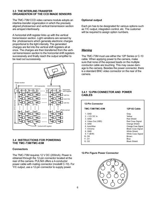
3.3 THE INTERLINE-TRANSFER<br />
ORGANIZATION OF THE CCD IMAGE SENSORS<br />
The TMC-73M CCD video camera module adopts an<br />
interline-transfer organization in which the precisely<br />
aligned photosensor and vertical transmission section<br />
are arrayed interlinearly.<br />
A horizontal shift register links up with the vertical<br />
transmission section. Light variations are sensed by<br />
the photosensors which generate electronic charges<br />
proportional to the light intensity. The generated<br />
charges are fed into the vertical shift registers all at<br />
once. The charges are then transferred from the vertical<br />
transmission section to the horizontal shift registers<br />
successively and finally reach the output amplifier to<br />
be read out successively.<br />
Optional output<br />
Each pin has to be designated for various options such<br />
as Y/C output, integration control, etc. The customer<br />
will be required to assign option numbers.<br />
Warning<br />
The TMC-73M must use either the 12P Series or C-10<br />
cable. When applying power to the camera, make<br />
sure that none of the exposed leads on the multiple<br />
conductor cable are touching. This may cause damage<br />
to the camera. Besides the power connector, there<br />
is a standard BNC video connector on the rear of the<br />
camera.<br />
Output section<br />
(818 elements)<br />
(513 elements)<br />
Horizontal<br />
shift register<br />
odd line<br />
even line<br />
odd line<br />
Photo senser<br />
3.4.1 12-PIN CONNECTOR AND POWER<br />
CABLES<br />
12-Pin Connector<br />
TMC-73M/TMC-63M<br />
12P-02 Cable<br />
Vertical shift register<br />
3.4 INSTRUCTIONS FOR POWERING<br />
THE TMC-73M/TMC-63M<br />
1. GND Gray<br />
2. +12V DC In Yellow<br />
3. GND Red Shield<br />
4. Video Out (VBS) Red Coax Signal<br />
5. GND Orange Shield<br />
6. Auto/Man Orange Coax Signal<br />
7. Chroma Black Coax Signal<br />
8. GND White Shield<br />
9. Y (B/W) White Coax Signal<br />
10. D0 Brown<br />
11. D1 Blue<br />
12. D2 Black Shield<br />
Connectors<br />
The TMC-73M requires 12 V DC (200mA). Power is<br />
obtained through the 12-pin connector located at the<br />
rear of the camera. PULNiX offers a 4-conductor<br />
power cable with mating connector (model# C-10). For<br />
Y/C output, use a 12-pin connector to supply power.<br />
12-Pin Figure Power Connector<br />
1 9<br />
2<br />
10<br />
8<br />
3<br />
11 12<br />
7<br />
4<br />
5<br />
6<br />
6