

1992-1996 Dodge Viper RT/10 - Paxton Superchargers
1992-1996 Dodge Viper RT/10 - Paxton Superchargers
1992-1996 Dodge Viper RT/10 - Paxton Superchargers

You also want an ePaper? Increase the reach of your titles
YUMPU automatically turns print PDFs into web optimized ePapers that Google loves.
Section 11<br />
TIMING CONTROLLER INSTALLATION<br />
11. TIMING CONTROLLER<br />
INSTALLATION<br />
***NOTE***<br />
The VIOLET wire is not used. Tape up the wire to avoid<br />
confusion.<br />
A. Using the supplied adhesive-backed Velcro,<br />
position the ignition timing control computer<br />
as shown in Fig. 11-a.<br />
IGNITION TIMING<br />
CONTROL COMPUTER<br />
and spade connector. The yellow water<br />
pump trigger wire (installed in section 9-c)<br />
should also be connected to the same power<br />
source. Use the supplied T-Tap and spade<br />
connector. (See Fig. 11-c.)<br />
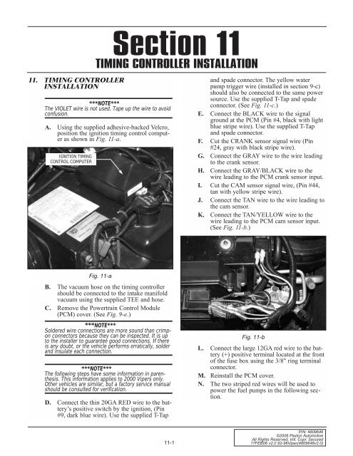
E. Connect the BLACK wire to the signal<br />
ground at the PCM (Pin #4, black with light<br />
blue stripe wire). Use the supplied T-Tap<br />
and spade connector.<br />
F. Cut the CRANK sensor signal wire (Pin<br />
#24, gray with black stripe wire).<br />
G. Connect the GRAY wire to the wire leading<br />
to the crank sensor.<br />
H. Connect the GRAY/BLACK wire to the<br />
wire leading to the PCM crank sensor input.<br />
I. Cut the CAM sensor signal wire, (Pin #44,<br />
tan with yellow stripe wire).<br />
J. Connect the TAN wire to the wire leading to<br />
the cam sensor.<br />
K. Connect the TAN/YELLOW wire to the<br />
wire leading to the PCM cam sensor input.<br />
(See Fig. 11-b.)<br />
Fig. 11-a<br />
B. The vacuum hose on the timing controller<br />
should be connected to the intake manifold<br />
vacuum using the supplied TEE and hose.<br />
C. Remove the Powertrain Control Module<br />
(PCM) cover. (See Fig. 9-e.)<br />
***NOTE***<br />
Soldered wire connections are more sound than crimpon<br />
connectors because they can be inspected. It is up<br />
to the installer to guarantee good connections. If there<br />
is any doubt, or the vehicle performs erratically, solder<br />
and insulate each connection.<br />
***NOTE***<br />
The following steps have some information in parenthesis.<br />
This information applies to 2000 <strong>Viper</strong>s only.<br />
Other vehicles are similar, but a factory service manual<br />
should be consulted for verification.<br />
D. Connect the thin 20GA RED wire to the battery’s<br />
positive switch by the ignition, (Pin<br />
#9, dark blue wire). Use the supplied T-Tap<br />
Fig. 11-b<br />
L. Connect the large 12GA red wire to the battery<br />
(+) positive terminal located at the front<br />
of the fuse box using the 3/8" ring terminal<br />
connector.<br />
M. Reinstall the PCM cover.<br />
N. The two striped red wires will be used to<br />
power the fuel pumps in the following section.<br />
11-1<br />
P/N: 4809646<br />
©2006 <strong>Paxton</strong> Automotive<br />
All Rights Reserved, Intl. Copr. Secured<br />
17FEB06 v2.0 92-96<strong>Viper</strong>(4809646v2.0)


