Marmitek IP Camera series advanced installation guide
Marmitek IP Camera series advanced installation guide
Marmitek IP Camera series advanced installation guide

Create successful ePaper yourself
Turn your PDF publications into a flip-book with our unique Google optimized e-Paper software.
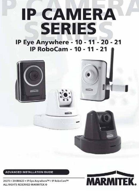
1 PREFACE<br />
Thank you for purchasing the <strong>Marmitek</strong> Wireless* Pan-Tilt**<br />
MPEG4/MJPEG*** Network <strong>Camera</strong>, a powerful dual-codec***<br />
wireless* network camera with the 1-way**** or 2-way***** audio<br />
function that provides the high-quality image and on-the-spot audio<br />
via the Internet connection. The Infrared LEDs and light sensor<br />
*****enable the camera to capture images even in the dark<br />
environment. The camera’s pan/tilt** functions allow you to control<br />
the camera to monitor everywhere remotely. Through the GPIO**<br />
connectors, the camera can attach a variety of external devices for<br />
your specific purposes. The camera can be installed as a standalone<br />
system within your application environment easily and quickly, and<br />
supports remote management function so that you can access and<br />
control it using a Web browser on your PC.<br />
Not all cameras have all the options installed. Options are marked<br />
with one or more * and have the following definition:<br />
*<strong>IP</strong> Eye AnyWhere 11, 21, <strong>IP</strong> RoboCam 11, 21<br />
** <strong>IP</strong> RoboCam 10, 11, 21<br />
***<strong>IP</strong> Eye AnyWhere 20, 21 <strong>IP</strong> RoboCam 21<br />
**** <strong>IP</strong> Eye AnyWhere 20, 21<br />
*****<strong>IP</strong> Robocam 21<br />
******<strong>IP</strong> Eye AnyWhere 10, 11, <strong>IP</strong> RoboCam 10, 11<br />
This Advanced Installation Guide provides you with the instructions<br />
and illustrations on how to use your camera, which includes:<br />
Chapter 1 Introduction to Your <strong>Camera</strong> describes the<br />
features of the camera. You will also know the components and<br />
functions of the camera.<br />
Chapter 2 Hardware Installation helps you install the camera<br />
according to your application environment. You can use<br />
this camera at home, at work, at any where you want.<br />
<strong>IP</strong> Eye Anywhere <strong>IP</strong> RoboCam 1
Chapter 3 Accessing the <strong>Camera</strong> lets you start using your<br />
camera without problem. The camera can be set up<br />
easily and work within your network environment<br />
instantly.<br />
Chapter 4 Configuring the <strong>Camera</strong> <strong>guide</strong>s you through the<br />
configuration of the camera using the Web browser on<br />
your PC.<br />
Chapter 5 Appendix provides the specification of the camera and<br />
some useful information for using your camera.<br />
NOTE The illustrations and configuration values in this <strong>guide</strong> are for<br />
reference only. The actual settings depend on your practical<br />
application of the camera.<br />
2<br />
© MARMITEK
2 CONTENTS<br />
0 ................................................................................ 0<br />
1 Preface ..................................................................... 1<br />
2 Contents.................................................................... 3<br />
3 SAFETY WARNINGS ................................................... 4<br />
C HAPTER 1......................................................................... 5<br />
I NTRODUCTION T O Y OUR C AMERA ............................................ 5<br />
1.1 CHECKING THE PACKAGE CONTENTS......................................................... 5<br />
1.2 GETTING TO KNOW YOUR CAMERA............................................................ 6<br />
FEATURES AND BENEFITS .................................................................................. 10<br />
1.4 SYSTEM REQUIREMENT........................................................................... 12<br />
C HAPTER 2....................................................................... 13<br />
H ARDW<br />
ARE I NSTALLATION .................................................... 13<br />
2.1 INSTALLING THE CAMERA STAND,WALL MOUNT KIT................................. 13<br />
2.2 CONNECTING THE CAMERA TO LAN/WLAN ............................................. 15<br />
2.3 APPLICATIONS OF THE CAMERA ............................................................... 16<br />
C HAPTER 3....................................................................... 17<br />
A CCESSING T HE C AMERA..................................................... 17<br />
3.1 USING <strong>IP</strong>FINDER..................................................................................... 17<br />
3.2 ACCESSING TO THE CAMERA ................................................................... 18<br />
3.3 CONFIGURING THE <strong>IP</strong> ADDRESS OF THE PC ............................................. 22<br />
C HAPTER 4....................................................................... 23<br />
C ONFIGURING T HE C AMERA.................................................. 23<br />
4.1 USING THE WEB CONFIGURATION............................................................ 23<br />
4.2 USING SMART WIZARD............................................................................ 24<br />
4.3 BASIC SETUP.......................................................................................... 28<br />
4.4 NETWORK SETTINGS............................................................................... 32<br />
4.5 PAN/TILT SETTINGS** ............................................................................. 40<br />
4.6 SETTING UP VIDEO &AUDIO .................................................................... 41<br />
4.7 EVENT SERVER CONFIGURATION............................................................. 46<br />
4.8 MOTION DETECT..................................................................................... 51<br />
4.9 EVENT CONFIG ....................................................................................... 52<br />
4.10 TOOLS.................................................................................................... 58<br />
4.11 USB*** .................................................................................................. 60<br />
4.12 INFORMATION ......................................................................................... 62<br />
A PPENDIX ........................................................................ 63<br />
A.1 SPECIFICATION ....................................................................................... 63<br />
A.2 GPIO TERMINAL APPLICATION**.............................................................. 65<br />
A.3 GLOSSARY OF TERMS ............................................................................. 67<br />
<strong>IP</strong> Eye Anywhere <strong>IP</strong> RoboCam 3
3 SAFETY WARNINGS<br />
o To prevent short circuits, this product should only be used inside and only in dry spaces.<br />
Do not expose the components to rain or moisture. Do not use the product close to a<br />
bath, swimming pool etc.<br />
o Do not expose the components of your systems to extremely high temperatures or<br />
bright light sources.<br />
o In case of improper usage or if you have altered and repaired the product yourself, all<br />
guarantees expire. <strong>Marmitek</strong> does not accept responsibility in the case of improper usage<br />
of the product or when the product is used for purposes other than specified. <strong>Marmitek</strong><br />
does not accept responsibility for additional damage other than covered by the legal<br />
product responsibility.<br />
o This product is not a toy. Keep out of reach of children.<br />
o Do not open the product: the device may contain live parts. The product should only be<br />
repaired or serviced by a qualified expert.<br />
o Only connect the adapter to the mains after checking whether the mains voltage is the<br />
same as the values on the identification tags. Never connect an adapter when it is<br />
damaged. In that case, contact your supplier.<br />
4<br />
© MARMITEK
CHAPTER 1<br />
INTRODUCTION TO YOUR<br />
CAMERA<br />
1.1 Checking the Package Contents<br />
Check the items contained in the package carefully. You should have<br />
the following:<br />
One Network <strong>Camera</strong>.<br />
One AC Power Adapter.<br />
One External Antenna.*<br />
One Wall Mount Kit.<br />
One GPIO Connector**<br />
One Ethernet Cable (RJ-45 type).<br />
One Installation CD-ROM.<br />
One Quick Installation Guide.<br />
NOTE Once any item contained is damaged or missing, contact the<br />
authorized dealer of your locale.<br />
<strong>IP</strong> Eye Anywhere <strong>IP</strong> RoboCam 5
1.2 Getting to Know Your <strong>Camera</strong><br />
Internal Microphone****<br />
allows the camera to<br />
receive sound and voice.<br />
Power LED indicates<br />
the camera is powered<br />
on with the steady<br />
amber light.<br />
Lens Assembly<br />
Link LED indicates<br />
the camera’s network<br />
connectivity with the<br />
flashing green light.<br />
USB Port*** allows you<br />
to connect an external<br />
USB device.<br />
It provides the power<br />
distribution up to 500mA.<br />
Front view <strong>IP</strong> Eye Anywhere<br />
USB*** Unmount<br />
Button<br />
Is used to remove the<br />
connected USB device<br />
safely.<br />
6<br />
© MARMITEK
Infrared LEDs (x7)*****<br />
allow your camera to<br />
capture clear image in<br />
a dark environment.<br />
Light Sensor *****<br />
is used to trigger on and off<br />
the Infrared LEDs according<br />
the environmental light level.<br />
Antenna*<br />
Lens Assembly<br />
Power LED<br />
indicates the<br />
camera is powered<br />
on with the steady<br />
amber light.<br />
Link LED<br />
indicates the camera’s<br />
network connectivity<br />
with the flashing green<br />
light.<br />
Internal Microphone *****<br />
allows the camera to receive<br />
sound and voice.<br />
Front view <strong>IP</strong> RoboCam<br />
USB Port***<br />
allows you to connect an<br />
external USB device. It<br />
provides the power<br />
distribution up to 500mA.<br />
The camera’s USB*** port supports WCN (Windows Connect Now)<br />
technology, which allows you to use the notebook computer to set<br />
up and store your wireless networking configuration on the USB<br />
storage device, and then retrieve the wireless settings when you<br />
connect the USB storage device to the camera.<br />
NOTE After long pressing the Unmount*** button for four seconds,<br />
the Power LED starts flashing. When the Power LED resumes<br />
the steady amber light, you can remove the USB device safely.<br />
<strong>IP</strong> Eye Anywhere <strong>IP</strong> RoboCam 7
External Antenna*<br />
Screw Hole is used<br />
to connect the camera<br />
stand.<br />
DC Power Connector<br />
is used to connect the<br />
AC power adapter, in<br />
order to supply power<br />
to the camera.<br />
Reset Button will restart<br />
the camera when it is<br />
pressed quickly; when it is<br />
long pressed for five<br />
seconds, the camera will<br />
resume the factory default<br />
settings.<br />
Ethernet Cable Connector<br />
is used to connect the<br />
network cable, which supports<br />
the NWay protocol so that the<br />
camera can detect the<br />
network speed automatically.<br />
Rear View <strong>IP</strong> Eye AnyWhere<br />
8<br />
© MARMITEK
Ethernet Cable Connector<br />
connects the network<br />
cable, which supports the<br />
NWay protocol so that the<br />
camera can detect the<br />
network speed<br />
automatically.<br />
External Antenna<br />
Connector* connects<br />
the external antenna.<br />
DC Power Connector<br />
connects the AC<br />
power adapter, in<br />
order to supply power<br />
to the camera.<br />
USB Unmount Button ***<br />
is used to remove the<br />
connected USB device<br />
safely.<br />
GPIO Connectors**<br />
is used to connect the<br />
external devices.<br />
Audio-out<br />
Connector*****<br />
connects an external<br />
active speaker.<br />
Reset Button<br />
will restart the camera when it<br />
is pressed quickly; when it is<br />
pressed and held for five<br />
seconds, the camera will<br />
resume the factory default<br />
settings.<br />
Rear View <strong>IP</strong> RoboCam<br />
<strong>IP</strong> Eye Anywhere <strong>IP</strong> RoboCam 9
Features and Benefits<br />
<br />
<br />
<br />
MPEG4/MJPEG Dual-codec Supported***<br />
The <strong>Marmitek</strong> <strong>IP</strong> camera provides you with excellent images by the<br />
MPEG4/ MJPEG dual-codec selectable technology, allowing you to<br />
adjust image size and quality, and bit rate according to the<br />
networking environment.<br />
1-way Audio Capability****<br />
The built-in microphone of the <strong>Marmitek</strong> <strong>IP</strong> Eye Anywhere camera<br />
provides on-the-spot audio via the Internet, allowing you to monitor<br />
the on-site voice.<br />
2-way Audio Capability*****<br />
The built-in microphone of the <strong>Marmitek</strong> <strong>IP</strong> RoboCam 21 camera<br />
provides on-the-spot audio via the Internet, allowing you to monitor<br />
the on-site voice. In addition, you can connect an external speaker to<br />
the camera to speak through the camera.<br />
<br />
<br />
<br />
10<br />
Day & Night Surveillance Supported*****<br />
The seven Infrared LEDs around the standard lens assembly enable<br />
the <strong>Marmitek</strong> <strong>IP</strong> RoboCam 21 to capture crystal clear images in the<br />
dark environment or at night. When the Light Sensor detects the<br />
environmental light level becomes low, the camera captures the<br />
images in black & white mode using these infrared LEDs.<br />
Optimal Viewing**<br />
With the pan/tile functions, you can easily monitor everywhere via<br />
the <strong>Marmitek</strong> <strong>IP</strong> RoboCam camera by moving the camera lens to the<br />
left/right (165/165 degrees) or up/down (90/15 degrees). In addition,<br />
you can assign up to eight positions for the camera, enabling you to<br />
move the camera lens to the desired position quickly.<br />
Supports RTSP***<br />
The camera supports RTSP (Real Time Streaming Protocol), which<br />
is a technology that allows you to view streaming media via the<br />
network. You can view the real-time video with the Quick Time player<br />
or RealPlayer. To view the real-time streaming image on your<br />
computer, open the Web browser and enter the RTSP link: rtsp://(<strong>IP</strong><br />
© MARMITEK
address of the camera)/mpeg4.<br />
Supports Multiple Profiles***<br />
The camera supports multiple profiles simultaneously, so that you<br />
can separately set up different image settings (such as image quality<br />
and frame rate) for the three video types of the camera: MPEG4,<br />
MJPEG, and 3GPP.<br />
I/O Connectors Provided**<br />
The <strong>Marmitek</strong> <strong>IP</strong> RoboCam camera provides the I/O connectors on<br />
the rear panel (IN/OUT), which provide the physical interface to send<br />
and receive digital signals to a variety of external alarm devices. You<br />
can connect a special featured device, and then configure the<br />
settings and control the device from the GPIO Trigger window of<br />
Web Configuration.<br />
Remote Control Supported<br />
By using a standard Web browser or the bundled UltraView software<br />
application, the administrator can easily change the configuration of<br />
the camera via Intranet or Internet. In addition, the camera can be<br />
upgraded remotely when a new firmware is available. The users are<br />
also allowed to monitor the image and take snapshots via the<br />
network.<br />
Supports Connection to the External Devices***** ***<br />
With the auxiliary Input/Output connectors, you can connect the<br />
camera to a variety of external devices, such as the external speaker<br />
and the USB device.<br />
Multiple Platforms Supported<br />
The camera supports multiple network protocols, including TCP/<strong>IP</strong>,<br />
SMTP e-mail, HTTP, and other Internet related protocols. Therefore,<br />
you can use the camera in a mixed operating system environment,<br />
such as Windows 2000 and Windows XP.<br />
Multiple Applications Supported<br />
Through the remote access technology, you can use the cameras to<br />
monitor various objects and places for your own purposes.<br />
For example, babies at home, patients in the hospital, offices and<br />
<strong>IP</strong> Eye Anywhere <strong>IP</strong> RoboCam 11
anks, and more. The camera can capture both still images and<br />
video clips, so that you can keep the archives and restore them at<br />
any time.<br />
1.4 System Requirement<br />
<br />
<br />
Networking<br />
LAN: 10Base-T Ethernet or 100Base-TX Fast Ethernet.<br />
WLAN*: IEEE 802.11b/g.<br />
Accessing the <strong>Camera</strong> using Web Browser<br />
Platform: Microsoft® Windows® 2000/XP/Vista/7<br />
CPU:<br />
Intel Pentium III 800MHz or above<br />
RAM: 128MB******<br />
512MB***<br />
Resolution: 800x600 or above<br />
User Interface: Microsoft® Internet Explorer 6.0 or above<br />
Apple Safari 2 or above<br />
Mozilla Firefox 2.00 or above<br />
<br />
Accessing the <strong>Camera</strong> using UltraView<br />
Platform: Microsoft® Windows® 2000/XP/Vista/7<br />
Hardware Requirement:<br />
1 camera connected: Intel Pentium III 800MHz; 512MB RAM<br />
2 ~ 4 cameras connected: Intel Pentium 4 1.3GHz; 512MB RAM<br />
5 ~ 8 cameras connected: Intel Pentium 4 2.4GHz; 1GB RAM<br />
9 ~ 16 cameras connected: Intel Pentium 4 3.4GHz; 2GB RAM<br />
Resolution: 1024x768 or above<br />
NOTE If you connect multiple cameras to monitor various places<br />
simultaneously, you are recommended to use a computer with<br />
higher performance.<br />
12<br />
© MARMITEK
CHAPTER 2<br />
HARDWARE INSTALLATION<br />
2.1 Installing the <strong>Camera</strong> Stand, Wall Mount<br />
Kit<br />
The <strong>Marmitek</strong> <strong>IP</strong> Eye Anywhere camera comes with a camera stand,<br />
which uses a swivel ball screw head to lock to the camera’s screw<br />
hole. When the camera stand is attached, you can place the camera<br />
anywhere by mounting the camera through the three screw holes<br />
located in the base of the camera stand.<br />
The <strong>Camera</strong> Stand<br />
<strong>IP</strong> Eye Anywhere <strong>IP</strong> RoboCam 13
The <strong>Marmitek</strong> <strong>IP</strong> RoboCam camera comes with a Wall Mount Kit,<br />
which allows you to place your camera anywhere by mounting the<br />
camera through the three screw holes located in the base of the Wall<br />
Mount Kit.<br />
Screw<br />
Wall Mount Kit<br />
Screw<br />
Screw<br />
14<br />
© MARMITEK
2.2 Connecting the <strong>Camera</strong> to LAN/WLAN<br />
Use the provided Ethernet cable<br />
to connect the camera to your<br />
local area network (LAN).<br />
When you connect the AC power<br />
adapter, the camera is powered<br />
on automatically. You can verify<br />
the power status from the Power<br />
LED on the front panel of the<br />
camera.<br />
Once connected, the Link LED<br />
starts flashing green light and the<br />
camera is on standby and ready<br />
for use now.<br />
Connecting the Ethernet Cable<br />
If you use a wireless network in<br />
your application environment, you<br />
need to attach the included<br />
external antenna to the camera.<br />
When the camera is powered on,<br />
the camera will automatically<br />
search any access point with<br />
“default” SSID.<br />
Connecting the External Antenna<br />
NOTE If the camera cannot to your wireless network, you need to<br />
install the camera in LAN and proceed with WLAN settings.<br />
<strong>IP</strong> Eye Anywhere <strong>IP</strong> RoboCam 15
2.3 Applications of the <strong>Camera</strong><br />
The camera can be applied in multiple applications, including:<br />
Monitor local and remote places and objects via Internet or<br />
Intranet.<br />
Capture still images and video clips remotely.<br />
Upload images or send email messages with the still images<br />
attached.<br />
The following diagram explains one of the typical applications for<br />
your camera and provides a basic example for installing the camera.<br />
*<br />
*<br />
* Please enclosed by<br />
waterproof housing<br />
when using in outdoor<br />
Home Applications<br />
16<br />
© MARMITEK
CHAPTER 3<br />
ACCESSING THE CAMERA<br />
3.1 Using <strong>IP</strong>Finder<br />
The <strong>Marmitek</strong> <strong>IP</strong> camera comes with a conveniently utility, <strong>IP</strong>Finder,<br />
which is included in the Installation CD-ROM, allowing you to search<br />
the camera on your network easily.<br />
1. Insert the Installation CD-ROM into your computer’s CD-ROM<br />
drive to initiate the Auto-Run program.<br />
2. Click the <strong>IP</strong>Finder item to launch the utility. The control panel<br />
will appear as below.<br />
Display the connected<br />
camera(s).<br />
Double click to link the<br />
<strong>Camera</strong>.<br />
Click About to get the Version information of <strong>IP</strong>Finder.<br />
Click Link to connect the selected camera.<br />
Click Change <strong>IP</strong> to modify the <strong>IP</strong> address of the selected camera.<br />
Click Search to find the <strong>IP</strong> address of the connected camera(s).<br />
Click Exit to close the utility.<br />
3. Once you get the <strong>IP</strong> address of the camera, launch the Web<br />
browser or UltraView to access your camera.<br />
<strong>IP</strong> Eye Anywhere <strong>IP</strong> RoboCam 17
3.2 Accessing to the <strong>Camera</strong><br />
Whenever you want to access the <strong>Marmitek</strong> <strong>IP</strong> camera:<br />
1. Connect your camera to the network (or the PC directly).<br />
2. Since the default configuration of the camera is DHCP mode<br />
enabled, you are recommended to launch <strong>IP</strong>Finder to search the<br />
<strong>IP</strong> address that is assigned to the camera by the DHCP server,<br />
and then click Link to access the camera via the Web browser.<br />
3. When the login window appears, enter the default User name<br />
(admin) and password (admin) and press OK to access to the<br />
main screen of the camera’s Web Configuration.<br />
Enter the User name<br />
and Password.<br />
NOTE If you are initially access to the camera, you will be ask to<br />
install a new plug-in for the camera. Permission request<br />
depends on the Internet security settings of your computer.<br />
Click Yes to proceed.<br />
After you login into the Web Configuration of the camera, the main<br />
18<br />
© MARMITEK
page will appear as below:<br />
Live View/Setup<br />
Switch<br />
Zoom In<br />
Buttons<br />
Nightmode Button<br />
<strong>Camera</strong> Information<br />
Compression<br />
Buttons<br />
Pan/Tilt Buttons<br />
Live View<br />
Image<br />
Function Buttons<br />
The main page of the Web Configuration provides you with many<br />
useful information and functions, including:<br />
<br />
<br />
<strong>Camera</strong> Information – Displays the camera’s location and the<br />
current date & time. The information can be modified in the Web<br />
Configuration.<br />
Live View Image – Displays the real-time image of the<br />
connected camera.<br />
Move your mouse to the Live View area and click on<br />
anywhere, the camera lens will then move to the position<br />
<strong>IP</strong> Eye Anywhere <strong>IP</strong> RoboCam 19
where you clicked to display it in the central part of Live View<br />
area.**<br />
When you enlarge the Live View by clicking the Zoom In<br />
buttons (2x or 3x), you can move the displayed image by<br />
right-clicking your mouse on the Live View area. The position<br />
where you right-clicked will be displayed in the central part of<br />
Live View area.**<br />
Zoom In Buttons – Click the buttons to zoom in the live view<br />
image by 1x, 2x, and 3x.<br />
Nightmode Button – Click the button to enable the “nightshot<br />
mode” to deliver clearer images in the dark environment.<br />
However, this will reduce the frame rate of video setting.<br />
Live View/Setup Switch – Click Setup to configure the<br />
camera. For details, see Chapter 4.<br />
Compression Buttons*** – Select to transmit and record the<br />
video using MPEG4 or MJPEG compression.<br />
Pan/Tilt Buttons** – Provides the buttons to control the <strong>IP</strong><br />
RoboCam camera lens:<br />
Left/Right/Up/Down/Home buttons allow you to move<br />
the camera lens position. Clicking the Home button will<br />
move the camera lens to the assigned home position.<br />
Up<br />
Left<br />
Home<br />
Right<br />
Down<br />
20<br />
Auto Patrol button controls the camera to automatically<br />
scan the preset positions once. Click Stop to stop patrolling.<br />
Click the Number button (1~8) to move the camera lens to<br />
the preset position immediately.<br />
© MARMITEK
To set up the preset positions, move the camera lens by<br />
clicking the Left/Right/Up/Down buttons to the desired<br />
position first, then select the number (1~8) from the pulldown<br />
list and click the Apply button. You can enter a<br />
descriptive name for the assigned position in the text box to<br />
identify it easily.<br />
<br />
Function Buttons – Use these buttons to control the audio,<br />
video, and trigger functions.<br />
Manual Record allows you to record and save a video clip.<br />
Snapshot allows you to capture and save a still image.<br />
Browse allows you to assign the destination folder to store<br />
the video clips and still images.<br />
Talk***** allows you to speak out through the <strong>IP</strong> RoboCam<br />
21 camera. Please note only one user is allowed to use this<br />
function at a time.<br />
Listen**** ***** allows you to receive the on-site sound and<br />
voice from the camera.<br />
Trigger Out** allows you to trigger on/off the GPIO output<br />
manually.<br />
NOTE If your PC uses Microsoft Vista platform, maybe you can’t find<br />
these recorded files stored by Snapshot or Manual Record.<br />
Then you need to disable the protected mode of Security in<br />
the IE Browser. Please follow the below Steps:<br />
1. Open IE Browser<br />
2. Select ToolsInternet Options<br />
3. Select Security<br />
<strong>IP</strong> Eye Anywhere <strong>IP</strong> RoboCam 21
4. Disable the ”Enable Protected Mode” then press OK<br />
3.3 Configuring the <strong>IP</strong> Address of the PC<br />
If you failed to access to the camera, please check the <strong>IP</strong> address of<br />
your computer. When you connect the camera to your computer<br />
directly to proceed with configuration of the camera, you need to set<br />
up the <strong>IP</strong> addresses to be in the same segment for the two devices<br />
to communicate.<br />
1. On your computer, click Start > Control Panel to open the<br />
Control Panel window.<br />
2. Double-click Network Connection to open the Network<br />
Connection window.<br />
3. Right-click Local Area Connection and then click<br />
Properties from the shortcut menu.<br />
4. When the Local Area Connection Properties window appears,<br />
select the General tab.<br />
5. Select Internet Protocol [TCP/<strong>IP</strong>] and then click Properties<br />
to bring up the Internet Protocol [TCP/<strong>IP</strong>] Properties window.<br />
6. To configure a fixed <strong>IP</strong> address that is within the segment of the<br />
camera, select the Use the following <strong>IP</strong> address option.<br />
Then, enter an <strong>IP</strong> address into the empty field. The suggested <strong>IP</strong><br />
address is 192.168.0.x (x is 1~254 except 30), and the<br />
suggested Subnet mask is 255.255.255.0.<br />
7. When you are finished, click OK.<br />
22<br />
© MARMITEK
CHAPTER 4<br />
CONFIGURING THE CAMERA<br />
4.1 Using the Web Configuration<br />
You can access and manage the <strong>Marmitek</strong> <strong>IP</strong> camera through the<br />
Web browser and the provided software application UltraView. This<br />
chapter describes the Web Configuration, and <strong>guide</strong>s you through<br />
the configuration of the camera by using the Web browser.<br />
To configure the camera, click Setup on the main page of Web<br />
Configuration. The Web Configuration will start from the Basic page.<br />
<strong>IP</strong> Eye Anywhere <strong>IP</strong> RoboCam 23
The Web Configuration contains the<br />
settings that are required for the<br />
camera in the left menu bar, including<br />
Smart Wizard, Basic, Network,<br />
Video/Audio, Event Server, Motion<br />
detect, Event Config, Tools, USB,<br />
and Information.<br />
4.2 Using Smart Wizard<br />
The <strong>Marmitek</strong> <strong>IP</strong> camera’s Smart Wizard lets you configure your<br />
camera easily and quickly. The wizard will <strong>guide</strong> you through the<br />
necessary settings with detailed instructions on each step.<br />
To start the wizard, click Smart Wizard in the left menu bar.<br />
Step 1. <strong>Camera</strong> Settings<br />
24<br />
© MARMITEK
Enter the name for<br />
the camera and<br />
place.<br />
Enter the<br />
administrator<br />
password.<br />
Step 2. <strong>IP</strong> Settings<br />
Select the <strong>IP</strong><br />
setting according<br />
to your network:<br />
DHCP, Static <strong>IP</strong>,<br />
or PPPoE.<br />
<strong>IP</strong> Eye Anywhere <strong>IP</strong> RoboCam 25
Step 3. Email Settings<br />
Enter the required<br />
information to be<br />
able to send email<br />
with image.<br />
Step 4. Wireless Networking*<br />
Complete the<br />
required settings<br />
for wireless<br />
networking.<br />
26<br />
© MARMITEK
Step 5. Confirm Settings<br />
This step shows the configuration of your camera. When you confirm<br />
the settings, click Apply to finish the wizard and reboot the camera.<br />
Otherwise, click Prev to go back to the previous step(s) and change<br />
the settings; or click Cancel to end the wizard and discard the<br />
changes.<br />
<strong>IP</strong> Eye Anywhere <strong>IP</strong> RoboCam 27
4.3 Basic Setup<br />
The Basic menu contains three sub-menus that provide the system<br />
settings for the camera, such as the <strong>Camera</strong> Name, Location, Date &<br />
Time, and User management.<br />
Basic >> System<br />
<br />
<br />
28<br />
Basic<br />
- <strong>Camera</strong> Name: Enter a descriptive name for the camera.<br />
- Location: Enter a descriptive name for the location used by<br />
the camera.<br />
Indication LED<br />
© MARMITEK
This item allows you to set the LED illumination as desired. There<br />
are two options: Normal and OFF.<br />
Basic >> Date & Time<br />
- TimeZone: Select the proper time zone for the region from<br />
the pull-down menu.<br />
- Synchronize with PC: Select this option and the date &<br />
time settings of the camera will be synchronized with the<br />
connected computer.<br />
- Synchronize with NTP Server: Select this option and the<br />
time will be synchronized with the NTP Server. You need to<br />
enter the <strong>IP</strong> address of the server and select the update<br />
interval in the following two boxes.<br />
- Manual: Select this option to set the date and time manually.<br />
<strong>IP</strong> Eye Anywhere <strong>IP</strong> RoboCam 29
Basic >> User<br />
<br />
<br />
30<br />
Administrator<br />
To prevent unauthorized access to the camera’s Web<br />
Configuration, you are strongly recommend to change the default<br />
administrator password. Type the administrator password twice to<br />
set and confirm the password.<br />
General User<br />
- User Name: Enter the user’s name you want to add to use<br />
the camera.<br />
- Password: Enter the password for the new user.<br />
When you are finished, click Add/Modify to add the new user<br />
© MARMITEK
to the camera. To modify the user’s information, select the one<br />
you want to modify from UserList and click Add/Modify.<br />
- UserList: Display the existing users of the camera. To delete<br />
a user, select the one you want to delete and click Delete.<br />
Guest<br />
- User Name: Enter the guest’s name you want to add to use<br />
the camera.<br />
- Password: Enter the password for the new guest.<br />
- UserList: Display the existing guests of the camera. To<br />
delete a user, select the one you want to delete and click<br />
Delete.<br />
NOTE The “General User” can access the camera and control the<br />
Function buttons of the camera’s Web Configuration; the<br />
“Guest’ can only view the live view image from the main page<br />
of the Web Configuration while accessing the camera. Only<br />
the “Administrator” is allowed to configure the camera through<br />
the Web Configuration.<br />
<strong>IP</strong> Eye Anywhere <strong>IP</strong> RoboCam 31
4.4 Network Settings<br />
The Network menu contains three sub-menus that provide the<br />
network settings for the camera, such as the <strong>IP</strong> Setting, DDNS<br />
Setting, <strong>IP</strong> Filter, and Wireless network**.<br />
Network >> Network<br />
<br />
32<br />
<strong>IP</strong> Setting<br />
© MARMITEK
This item allows you to select the <strong>IP</strong> address mode and set up<br />
the related configuration. The default setting is DHCP mode<br />
enabled.<br />
- DHCP: Select this option when your network uses the DHCP<br />
server. When the camera starts up, it will be assigned an <strong>IP</strong><br />
address from the DHCP server automatically.<br />
- Static <strong>IP</strong>: Select this option to assign the <strong>IP</strong> address for the<br />
camera directly. You can use <strong>IP</strong>Finder to obtain the related<br />
setting values.<br />
<strong>IP</strong><br />
Subnet Mask<br />
Default Gateway<br />
Primary/<br />
Secondary DNS<br />
Enter the <strong>IP</strong> address of the camera. The<br />
default setting is 192.168.0.30.<br />
Enter the Subnet Mask of the camera. The<br />
default setting is 255.255.255.0.<br />
Enter the Default Gateway of the camera.<br />
The default setting is 192.168.0.1.<br />
DNS (Domain Name System) translates<br />
domain names into <strong>IP</strong> addresses. Enter the<br />
Primary DNS and Secondary DNS that are<br />
provided by ISP.<br />
- PPPoE: Select this option when you use a direct connection<br />
via the ADSL modem. You should have a PPPoE account from<br />
your Internet service provider. Enter the User Name and<br />
Password. The camera will get an <strong>IP</strong> address from the ISP<br />
as starting up.<br />
NOTE Once the camera get an <strong>IP</strong> address from the ISP as starting<br />
up, it automatically sends a notification email to you.<br />
Therefore, when you select PPPoE as your connecting type,<br />
you have to set up the email or DDNS configuration in<br />
advance.<br />
<br />
DDNS Setting<br />
<strong>IP</strong> Eye Anywhere <strong>IP</strong> RoboCam 33
With the Dynamic DNS feature, you can assign a fixed host and<br />
domain name to a dynamic Internet <strong>IP</strong> address. Select the<br />
Enable option to enable this feature. Then, select the Provider<br />
from the pull-down list and enter the required information in the<br />
Host Name, User Name, and Password boxes. Please note<br />
that you have to sign up for DDNS service with the service<br />
provider first.<br />
UPnP<br />
The camera supports UPnP (Universal Plug and Play), which is a<br />
set of computer network protocols that enable the device-todevice<br />
interoperability. In addition, it supports port auto mapping<br />
function so that you can access the camera if it is behind an NAT<br />
router or firewall. Select the Enable option to enable this feature.<br />
Bonjour*****<br />
The devices with Bonjour will automatically broadcast their own<br />
services and listen for services being offered for the use of others.<br />
So if your Browser has Bonjour then you can find the camera on<br />
your local network without knowing its <strong>IP</strong> address.<br />
The Apple Safari already has Bonjour. You can download the<br />
complete Bonjour for IE Browser from Apple's web site by visiting<br />
http://www.apple.com/bonjour/.<br />
<br />
Ports Number<br />
- HTTP Port: The default HTTP port is 80.<br />
- RTSP*** Port: Configure the transmission of streaming data<br />
within the network. The default RTSP (Real Time Streaming<br />
Protocol) port is 554.<br />
NOTE If the camera is behind an NAT router of firewall, the<br />
suggested range to be used is from 1024 to 65535.<br />
34<br />
© MARMITEK
Network >> <strong>IP</strong> Filter<br />
The <strong>IP</strong> Filter setting allows the administrator of the camera to limit<br />
the users within a certain range of <strong>IP</strong> addresses to access the<br />
camera.<br />
<br />
Start/End <strong>IP</strong> Address<br />
Assign a range of <strong>IP</strong> addresses that are not allowed to access the<br />
camera by entering the Start <strong>IP</strong> address and End <strong>IP</strong> address.<br />
When you are finished, click Add to save the range setting. You<br />
can repeat the action to assign multiple ranges for the camera.<br />
For example, when you enter 192.168.0.50 in Start <strong>IP</strong> Address<br />
and 192.168.0.80 in End <strong>IP</strong> Address, the user whose <strong>IP</strong> address<br />
located within 192.168.0.50 ~ 192.168.0.80 will not be allowed to<br />
access the camera.<br />
<strong>IP</strong> Eye Anywhere <strong>IP</strong> RoboCam 35
Deny <strong>IP</strong> List<br />
The list displays the range setting(s) of <strong>IP</strong> addresses that are not<br />
allowed to access the camera. To clear the setting, select a range<br />
of <strong>IP</strong> addresses from the list and click Delete.<br />
36<br />
© MARMITEK
Network >> Wireless Setting*<br />
The camera supports WLAN while you use the wireless network.<br />
Select the Enable option to enable this feature.<br />
- Network ID (SSID}: Keep the default setting of this option to<br />
connect the camera to any access point under the<br />
infrastructure network mode. To connect the camera to a<br />
specified access point, set a SSID for the camera to<br />
correspond with the access point’s ESS-ID. To connect the<br />
camera to an Ad-Hoc wireless workgroup, set the same<br />
wireless channel and SSID to match with the computer’s<br />
configuration.<br />
<strong>IP</strong> Eye Anywhere <strong>IP</strong> RoboCam 37
Click Site Survey to display the available wireless networks,<br />
so that you can easily connect to one of the listed wireless<br />
networks.<br />
List of searching results<br />
- Wireless Mode: Select the type of wireless communication<br />
for the camera: Infrastructure or Ad-Hoc.<br />
- Channel: Select the appropriate channel from the list.<br />
- Authentication: Select the authentication method to secure<br />
the camera from being used by unauthorized user: Open,<br />
Shared-key, WPA-PSK, and WPA2-PSK. The following<br />
table explains the four options:<br />
Open<br />
Shared-key<br />
WPA-PSK/<br />
WPA2-PSK<br />
The default setting of Authentication mode,<br />
which communicates the key across the network.<br />
Allow communication only with other devices<br />
with identical WEP settings.<br />
WPA-PSK/WPA2-PSK is specially designed for<br />
the users who do not have access to network<br />
authentication servers. The user has to manually<br />
enter the starting password in their access point<br />
or gateway, as well as in each PC on the<br />
wireless network.<br />
If you select Open or Shared-key as the Authentication mode,<br />
you need to complete the following settings:<br />
38<br />
© MARMITEK
Encryption: Select the WEP option to enable the data<br />
encryption feature to secure the camera within the wireless<br />
network.<br />
Format: Once you enable the Encryption feature, you need<br />
to determine the encryption format by selecting ASCII or<br />
HEX. ASCII format causes each character you type to be<br />
interpreted as an eight-bit value. Hex format causes each pair<br />
of characters you type to be interpreted as an eight-bit value<br />
in hexadecimal (base 16) notation.<br />
Key Length: Select the WEP key length you use: 64 bits or<br />
128 bits.<br />
WEP Key 1/2/3/4: Enter the WEP key(s) in the following<br />
boxes.<br />
If you select WPA-PSK or WPA2-PSK as the Authentication<br />
mode, you need to complete the following settings:<br />
Encryption: Select TK<strong>IP</strong> or AES. TK<strong>IP</strong> (Temporal Key<br />
Integrity Protocol) changes the temporal key every 10,000<br />
packets to insure much greater security than the standard<br />
WEP security. AES (Advanced Encryption Standard) is used<br />
to ensure the highest degree of security and authenticity for<br />
digital information.<br />
Pre-Shared Key: This is used to identify each other in the<br />
network. Enter the name in the box, and this name must<br />
match the Pre-shared key value in the remote device.<br />
<strong>IP</strong> Eye Anywhere <strong>IP</strong> RoboCam 39
4.5 Pan/Tilt Settings**<br />
The Pan/Tilt menu allows you to configure the pan/tilt functions of the<br />
camera.<br />
Pan & Tilt >> Pan & Tilt Settings<br />
- Pan/Tilt Calibration: Click Calibration to calibrate the<br />
position of the camera lens.<br />
- Pan Steps: Set the changing range (1~20 degrees) when<br />
you click the Left/Right button.<br />
- Tilt Steps: Set the changing range (1~20 degrees) when you<br />
click the Up/Down button.<br />
- Auto Patrol Stay Time: Set the stay time (1~999 seconds)<br />
of each preset positions when the camera is patrolling.<br />
40<br />
© MARMITEK
4.6 Setting up Video & Audio<br />
The Video & Audio menu contains three sub-menus that provide the<br />
video and audio settings for the camera.<br />
Video & Audio >> <strong>Camera</strong><br />
<br />
Image Setting<br />
- Brightness: Adjust the brightness level from 0 ~ 100.<br />
<strong>IP</strong> Eye Anywhere <strong>IP</strong> RoboCam 41
- Contrast: Adjust the contrast level from 0 ~ 100.<br />
<br />
- Saturation: Adjust the colors level from 0 ~ 100.<br />
Click Default to restore the default settings of the three options<br />
above.<br />
- Mirror: Select the Horizontal option to mirror the image<br />
horizontally. Select the Vertical option to mirror the image<br />
vertically.<br />
- Light Frequency: Select the proper frequency according to<br />
the camera’s location: 50Hz, 60Hz, or Outdoor.<br />
Overlay Setting<br />
- Includes Date & Time: Select this option to display the date<br />
& time stamp on the live view image.<br />
- Enable Opaque: Select this option to set a black<br />
background to the displayed date & time stamp.<br />
42<br />
© MARMITEK
Video & Audio >> Video<br />
<br />
MPEG4***<br />
- Video Resolution: Select the desired video resolution from<br />
the three formats: VGA, QVGA and QQVGA. The higher<br />
setting (VGA) obtains better video quality while it uses more<br />
resource within your network.<br />
- Video Quality: Select the desired image quality from five<br />
levels: Lowest, Low, Medium, High, and Highest.<br />
- Frame Rate: Select Auto or a proper setting depending on<br />
your network status.<br />
<strong>IP</strong> Eye Anywhere <strong>IP</strong> RoboCam 43
MJPEG<br />
- Video Resolution: Select the desired video resolution from<br />
the three formats: VGA, QVGA and QQVGA. The higher<br />
setting (VGA) obtains better video quality while it uses more<br />
resource within your network.<br />
- Video Quality: Select the desired image quality from five<br />
levels: Lowest, Low, Medium, High, and Highest.<br />
- Frame Rate: Select Auto or a proper setting depending on<br />
your network status.<br />
NOTE The camera supports both MPEG4 and MJPEG compression.<br />
MJPEG capture the images in JPEG format, which require<br />
higher bandwidth to view smooth video. The administrator can<br />
control the bandwidth of each connection well through the<br />
setting options above.<br />
<br />
3GPP***<br />
The camera supports 3GPP specification. Select the Disable<br />
option to disable this feature. Otherwise, select 3GPP Without<br />
Audio or 3GPP With Audio to transfer the video clips without<br />
or with audio.<br />
If you use a mobile phone that supports 3GPP, you can also view<br />
the real-time streaming image captured by the camera on your<br />
phone (with the default player on the phone) by entering the<br />
RTSP link: rtsp://(<strong>IP</strong> address of the camera)/3gp.<br />
NOTE Your mobile phone and the service provider must support<br />
3GPP function. Please contact your service provider when<br />
you are failed to use this service.<br />
44<br />
© MARMITEK
Video & Audio >> Audio**** *****<br />
<strong>Camera</strong> Microphone In**** *****<br />
<br />
Select the Enable option to enable the camera’s audio function,<br />
so that you can receive the on-site sound and voice from the<br />
camera.<br />
<strong>Camera</strong> Speaker Out*****<br />
Select the Enable option to enable the <strong>IP</strong> RoboCam 21<br />
camera’s external speaker function, so that the connected<br />
speaker can play the sound and voice through the camera.<br />
- Volume: Set the speaker’s volume.<br />
<strong>IP</strong> Eye Anywhere <strong>IP</strong> RoboCam 45
4.7 Event Server Configuration<br />
The Event Server menu contains three sub-menus that allow you to<br />
upload images to FTP, send emails that include still images, and<br />
store the images to a NAS system.<br />
When you complete the required settings for FTP, Email, or Network<br />
Storage, click Test to test the related configuration is correct or not.<br />
Once the camera connects to the server successfully, click Apply.<br />
Event Server Setting>> FTP<br />
- Host Address: Enter the <strong>IP</strong> address of the target FTP server.<br />
- Port Number: Enter the port number used for the FTP server.<br />
- User Name: Enter the user name to login into the FTP server.<br />
46<br />
© MARMITEK
- Password: Enter the password to login into the FTP server.<br />
- Directory Path: Enter the destination folder for uploading the<br />
images. For example, /Test/.<br />
- Passive Mode: Select the Enable option to enable passive<br />
mode.<br />
NOTE Due to the network environment, the camera may not upload<br />
the number of images that you set.<br />
<strong>IP</strong> Eye Anywhere <strong>IP</strong> RoboCam 47
Event Server Setting >> Email<br />
48<br />
- SMTP Server Address: Enter the mail server address. For<br />
example, smtp.com.<br />
- Sender Email Address: Enter the email address of the<br />
user who will send the email. For example, mymail@mail.com.<br />
- Sender User Name: Enter the user name to login the mail<br />
server.<br />
- Sender Password: Enter the password to login the mail<br />
server.<br />
- Receiver #1 Email Address: Enter the first email address<br />
of the user who will receive the email.<br />
© MARMITEK
- Receiver #2 Email Address: Enter the second email<br />
address of the user who will receive the email.<br />
NOTE***** Due to the network environment, the camera may not<br />
send the number of images that you set.<br />
Event Server Setting >> Network Storage***<br />
- Samba Server Address: Enter the <strong>IP</strong> address of the Network<br />
Storage server.<br />
- Share: Assign the folder on the Network Storage server to share<br />
the files to users.<br />
- Path: Assign the path for uploading the files on the Network<br />
Storage server. For example, /Test/.<br />
<strong>IP</strong> Eye Anywhere <strong>IP</strong> RoboCam 49
- User Name: Enter the user name to login into the Network<br />
Storage server.<br />
- Password: Enter the password to login into the Network Storage<br />
server.<br />
- Split By: When the file is too large to upload smoothly, use this<br />
option to split it by selecting File Size or Recording Time.<br />
- When Disk Full: Select Stop Recording or Recycle – Delete<br />
Oldest Folder of File when the storage space on the Network<br />
Storage server is full.<br />
NOTE The video recorded files in Network Storage are enclosed by<br />
AVI format without Audio.<br />
50<br />
© MARMITEK
4.8 Motion Detect<br />
The Motion Detect menu contains the command and option that<br />
allow you to enable and set up the motion detection feature of the<br />
camera. The camera provides two detecting areas.<br />
To enable the detecting area, select Window 1 or 2 from the pulldown<br />
list, and then select Enable. When the detecting area is<br />
enabled, you can use the mouse to move the detecting area and<br />
change the area coverage.<br />
- Name: Assign a name to the detecting area.<br />
- Threshold: Move the slide bar to adjust the level for<br />
detecting motion to record video.<br />
<strong>IP</strong> Eye Anywhere <strong>IP</strong> RoboCam 51
NOTE Sliding the Threshold bar to the right will decrease the<br />
sensitivity of motion detection; sliding the Threshold bar to the<br />
left will increase the sensitivity of motion detection<br />
NOTE keep the two motion detection areas to a minimum size<br />
because this gives much bigger detection spikes, and the threshold<br />
can therefore be set higher, and so reduce false alerts due to<br />
sunlight changes.<br />
4.9 Event Config<br />
The Event Config menu contains sub-menus that provide the<br />
commands to configure event profiles.<br />
Event Configuration >> General Setting<br />
52<br />
© MARMITEK
- Snapshot/Recording Subfolder: You can assign a<br />
descriptive name for the subfolder to save the captured<br />
image/video files. Otherwise, leave this option blank to use the<br />
default setting.<br />
- Network Storage Recording Time Per Event***: Limit<br />
the recording time while you are using the Network Storage<br />
solution.<br />
- GPIO Trigger Out Retention Time Per Event**: Limit<br />
the retention time of the GPIO Trigger Out function.<br />
Event Configuration >> Arrange Schedule Profile<br />
This sub-menu displays the scheduled profile(s). To customize the<br />
profile, click Add and then enter a descriptive name for the profile in<br />
the prompt dialog window. After entering the profile name, click OK<br />
and the profile is added to the Schedule Profiles list. To delete the<br />
profile, select the profile in the list and click Delete.<br />
<strong>IP</strong> Eye Anywhere <strong>IP</strong> RoboCam 53
- Profile Name: Display the profile name that you select in the<br />
Schedule Profiles list.<br />
- Weekdays: Select the weekday(s) that you want to<br />
separately assign in the schedule profile. The weekday that<br />
has been assigned will be displayed with green color.<br />
- Time List: Display the time period that you have assigned<br />
within the selected weekday. To assign the same time period<br />
to every weekday, click Add this to all weekdays; click<br />
Delete this from all weekdays to remove the selected<br />
time period from every weekday. Click Delete to remove the<br />
selected time period.<br />
- Start/End Time: Enter the start and end time and then click<br />
Add to assign a time period within in the selected weekday.<br />
Event Configuration >> Motion Detect Trigger<br />
Select the Enable option to enable the motion detect trigger function<br />
of the camera, so that you can set Trigger Out function or send<br />
captured images within the detecting area to the FTP server, email<br />
receiver, Network Storage server, or the connected USB device. You<br />
have to configure corresponding settings, such as FTP server and<br />
email server, to enable this feature.<br />
54<br />
© MARMITEK
- Schedule Profile: Select a schedule profile from the pulldown<br />
list.<br />
- Action: Set the Trigger Out** function or select the<br />
destination of the captured images: Save Image to USB***,<br />
Record to Network Storage***, Send Email, or FTP<br />
Upload.<br />
Event Configuration >> Schedule Trigger<br />
You can separately configure the schedule for trigger function of the<br />
<strong>Marmitek</strong> <strong>IP</strong> camera by Email, FTP, or Network Storage***.<br />
<strong>IP</strong> Eye Anywhere <strong>IP</strong> RoboCam 55
Select the Enable option on each item, and then select a<br />
Schedule Profile from the pull-down list and set the Interval time.<br />
NOTE If the setting value of the Network Storage Recording Time<br />
Per Event option in General Setting is longer than the<br />
Interval time in Network Storage Schedule, the recorded file<br />
will be a continuous video clip.<br />
For example, if you set the Network Storage Recording<br />
Time Per Event as 10 seconds and the Interval as 5 seconds,<br />
recorded file becomes a non-stop video clip because the<br />
camera will record a 10-second video clip every 5 seconds.<br />
56<br />
© MARMITEK
Event Configuration >> GPIO Trigger**<br />
Select the Enable option to enable the GPIO trigger function of the<br />
camera, so that you can set Trigger Out function or send captured<br />
images within the detecting area to the FTP server, email receiver,<br />
Network Storage server***, or the connected USB*** device. You<br />
have to configure corresponding settings, such as FTP server and<br />
email server, to enable this feature.<br />
- Schedule Profile: Select a schedule profile from the pulldown<br />
list.<br />
- Action: Set the Trigger Out function or select the<br />
destination of the captured images: Save Image to USB***,<br />
<strong>IP</strong> Eye Anywhere <strong>IP</strong> RoboCam 57
Record to Network Storage***, Send Email, or FTP<br />
Upload.<br />
4.10 Tools<br />
The Tools menu provides the commands that allow you to restart or<br />
reset the <strong>Marmitek</strong> <strong>IP</strong> camera. You can also backup and restore your<br />
configuration, and upgrade the firmware for the camera.<br />
58<br />
© MARMITEK
Factory Reset<br />
Click Reset to restore all factory default settings for the camera.<br />
System Reboot<br />
Click Reboot to restart the camera just like turning the device off<br />
and on. The camera configuration will be retained after rebooting.<br />
Configuration<br />
You can save your camera configuration as a backup file on your<br />
computer. Whenever you want to resume the original settings,<br />
you can restore them by retrieving the backup file.<br />
- Backup: Click Get the backup file to save the current<br />
configuration of the camera.<br />
- Restore: Click Browse to locate the backup file and then<br />
click Restore.<br />
Update Firmware<br />
This item displays the current firmware version. You can upgrade<br />
the firmware for your camera once you obtained a latest version<br />
of firmware.<br />
- Select the firmware: Click Browse to locate the backup<br />
file and then click Update.<br />
NOTE Make sure to keep the camera connected to the power source<br />
during the process of upgrading firmware. Otherwise, the<br />
camera might be damaged because of failure of upgrading<br />
firmware.<br />
<strong>IP</strong> Eye Anywhere <strong>IP</strong> RoboCam 59
4.11 USB***<br />
The USB menu provides the information and controls of the<br />
connected USB device.<br />
<br />
<br />
<br />
USB Dismount<br />
To safely remove the connected USB device, you can press the<br />
Unmount button for four seconds on the camera or click<br />
Dismount from this item.<br />
USB Information<br />
Display the Total space and Free space of the USB device.<br />
USB Setting<br />
60<br />
© MARMITEK
- When Disk Full: Select Stop Recording or Recycle –<br />
Delete Oldest Folder of File when the storage space on<br />
the USB device is full.<br />
NOTE The connected USB storage device can be used to store still<br />
images only and as your host system backup. It is not<br />
recommended to use the USB device as your major storage<br />
device.<br />
<strong>IP</strong> Eye Anywhere <strong>IP</strong> RoboCam 61
4.12 Information<br />
The Information menu displays the current configuration and events<br />
log of the camera.<br />
<br />
<br />
Device Info<br />
Display the Basic, Video & Audio, Network, and Wireless settings<br />
of the camera.<br />
System Log<br />
The Logs table displays the events log recorded by the system.<br />
62<br />
© MARMITEK
APPENDIX<br />
A.1 Specification<br />
<br />
<br />
<br />
Image Sensor<br />
Sensor 1/4” color CMOS<br />
Resolution 640x480<br />
Video<br />
Compression MJPEG******<br />
MPEG4/MJPEG***<br />
Video resolution VGA/QVGA/QQVGA; 30fps max.<br />
Audio<br />
Input**** *****<br />
Output*****<br />
Codec<br />
Built-in MIC<br />
Mono 3.5 mm mini jack plug<br />
PCM/AMR (AMR is for 3GPP only)<br />
User Interface<br />
LAN One RJ-45 port<br />
Antenna* One external antenna<br />
Reset One Reset button<br />
USB*** USB 1.1 port, with one unmount button;<br />
Power distribution: 500mA Max.<br />
Support FAT, FAT32 file system<br />
GPIO** 1 in/1 out connectors<br />
Input: active high: 9~40V DC; dropout: 0V DC<br />
Output: close circuit current 70mA AC or<br />
100mA DC maximum, 30 Ohm; open circuit<br />
voltage 240V AC or 350V DC maximum<br />
LEDs<br />
Power LED (amber); Link LED (green)<br />
<strong>IP</strong> Eye Anywhere <strong>IP</strong> RoboCam 63
System Hardware<br />
Processor ARM9 base<br />
RAM<br />
32MB SDRAM<br />
ROM<br />
4MB NOR Flash******<br />
8MB NOR Flash***<br />
Power<br />
DC 12V(<strong>IP</strong> Robocam)<br />
Communication<br />
LAN<br />
WLAN*<br />
Protocol support******<br />
DC 5V (<strong>IP</strong> Eye AnyWhere)<br />
10/100Mbps Fast Ethernet, auto-sensed,<br />
Auto-MDIX<br />
IEEE 802.11b/g<br />
TCP/<strong>IP</strong>, UDP, ICMP, DHCP, NTP,<br />
DNS, DDNS, SMTP, FTP, HTTP, PPPoE,<br />
UPnP.<br />
Protocol support*** TCP/<strong>IP</strong>, UDP, ICMP, DHCP, NTP,<br />
DNS, DDNS, SMTP, FTP, Samba, PPPoE,<br />
UPnP, RTP, RTSP, RTCP<br />
Protocol support***** TCP/<strong>IP</strong>, UDP, ICMP, DHCP, NTP,<br />
DNS, DDNS, SMTP, FTP, Samba, PPPoE,<br />
UPnP, Bonjour, RTP, RTSP, RTCP<br />
Pan/Tilt**<br />
Pan<br />
165 degree (left) to 165 degree (right)<br />
Tilt<br />
90 degree (up) to 15 degree (down)<br />
Software<br />
OS Support Windows 2000/XP/Vista/7<br />
Browser<br />
Internet Explorer 6.0 or above<br />
Apple Safari 2 or above<br />
Mozilla Firefox 2.00 or above<br />
Software UltraView for playback/recording/<br />
configuration features<br />
<br />
Operating Environment<br />
64<br />
© MARMITEK
Temperature<br />
Humidity<br />
EMI<br />
FCC Class B, CE Class B<br />
- Operation: 0C ~ 45C<br />
- Storage: -15C ~ 60C<br />
- Operation: 20% ~ 85% non-condensing<br />
- Storage: 0% ~ 90% non-condensing<br />
A.2 GPIO Terminal Application**<br />
Typically used in association with programming scripts for<br />
developing applications for motion detection, event triggering, alarm<br />
notification via e-mail, and a variety of external control functions. The<br />
GPIO connectors are located on the rear panel of the camera, which<br />
provide the interface of connecting the sensor device (IN) and<br />
controlled device (OUT).<br />
Connector Pin Assignment<br />
PIN<br />
IN<br />
OUT<br />
SPECIFICATION<br />
Active High voltage 9~40V DC;<br />
Dropout-out voltage 0V DC<br />
Close circuit current 70mA AC or 100mA DC maximum,<br />
Output resistance 30 Ohm;<br />
Open circuit voltage 240V AC or 350V DC maximum<br />
<strong>IP</strong> Eye Anywhere <strong>IP</strong> RoboCam 65
Interface Schematic<br />
NOTE:You can use a <strong>Marmitek</strong> SM10 Universal X-10 sender to<br />
transform the output into an X-10 signal for controlling appliances<br />
and lights , that are plugged into the <strong>Marmitek</strong> X-10 modules,<br />
through the existing house wiring. Automatically switches all lights<br />
(on or flashing) in case of alarm, without running any extra wires.<br />
Switch appliances and lights in your home without extra cables.<br />
66<br />
© MARMITEK
A.3 Glossary of Terms<br />
NUMBERS<br />
10BASE-T<br />
100BASE-TX<br />
10BASE-T is Ethernet over UTP Category III, IV, or V<br />
unshielded twisted-pair media.<br />
The two-pair twisted-media implementation of 100BASE-<br />
T is called 100BASE-TX.<br />
A<br />
ADPCM<br />
AMR<br />
Applet<br />
ASCII<br />
ARP<br />
AVI<br />
Adaptive Differential Pulse Code Modulation, a new<br />
technology improved from PCM, which encodes analog<br />
sounds to digital form.<br />
AMR (Adaptive Multi-Rate) is an audio data compression<br />
scheme optimized for speech coding, which is adopted<br />
as the standard speech codec by 3GPP.<br />
Applets are small Java programs that can be embedded<br />
in an HTML page. The rule at the moment is that an<br />
applet can only make an Internet connection to the<br />
computer form that the applet was sent.<br />
American Standard Code For Information Interchange, it<br />
is the standard method for encoding characters as 8-bit<br />
sequences of binary numbers, allowing a maximum of<br />
256 characters.<br />
Address Resolution Protocol. ARP is a protocol that<br />
resides at the TCP/<strong>IP</strong> Internet layer that delivers data on<br />
the same network by translating an <strong>IP</strong> address to a<br />
physical address.<br />
Audio Video Interleave, it is a Windows platform audio<br />
and video file type, a common format for small movies<br />
and videos.<br />
B<br />
BOOTP<br />
Bootstrap Protocol is an Internet protocol that can<br />
automatically configure a network device in a diskless<br />
workstation to give its own <strong>IP</strong> address.<br />
<strong>IP</strong> Eye Anywhere <strong>IP</strong> RoboCam 67
C<br />
Communication<br />
Connection<br />
Communication has four components: sender, receiver,<br />
message, and medium. In networks, devices and<br />
application tasks and processes communicate messages<br />
to each other over media. They represent the sender and<br />
receivers. The data they send is the message. The<br />
cabling or transmission method they use is the medium.<br />
In networking, two devices establish a connection to<br />
communicate with each other.<br />
D<br />
DHCP<br />
DNS<br />
Developed by Microsoft, DHCP (Dynamic Host<br />
Configuration Protocol) is a protocol for assigning<br />
dynamic <strong>IP</strong> addresses to devices on a network. With<br />
dynamic addressing, a device can have a different <strong>IP</strong><br />
address every time it connects to the network. In some<br />
systems, the device's <strong>IP</strong> address can even change while<br />
it is still connected. It also supports a mix of static and<br />
dynamic <strong>IP</strong> addresses. This simplifies the task for<br />
network administrators because the software keeps track<br />
of <strong>IP</strong> addresses rather than requiring an administrator to<br />
manage the task. A new computer can be added to a<br />
network without the hassle of manually assigning it a<br />
unique <strong>IP</strong> address. DHCP allows the specification for the<br />
service provided by a router, gateway, or other network<br />
device that automatically assigns an <strong>IP</strong> address to any<br />
device that requests one.<br />
Domain Name System is an Internet service that<br />
translates domain names into <strong>IP</strong> addresses. Since<br />
domain names are alphabetic, they're easier to<br />
remember. The Internet however, is really based on <strong>IP</strong><br />
addresses every time you use a domain name the DNS<br />
will translate the name into the corresponding <strong>IP</strong><br />
address. For example, the domain name<br />
www.network_camera.com might translate to<br />
192.167.222.8.<br />
E<br />
68<br />
© MARMITEK
Enterprise<br />
network<br />
Ethernet<br />
An enterprise network consists of collections of networks<br />
connected to each other over a geographically dispersed<br />
area. The enterprise network serves the needs of a<br />
widely distributed company and operates the company’s<br />
mission-critical applications.<br />
The most popular LAN communication technology. There<br />
are a variety of types of Ethernet, including 10Mbps<br />
(traditional Ethernet), 100Mbps (Fast Ethernet), and<br />
1,000Mbps (Gigabit Ethernet). Most Ethernet networks<br />
use Category 5 cabling to carry information, in the form<br />
of electrical signals, between devices. Ethernet is an<br />
implementation of CSMA/CD that operates in a bus or<br />
star topology.<br />
F<br />
Fast Ethernet<br />
Firewall<br />
Fast Ethernet, also called 100BASE-T, operates at 10 or<br />
100Mbps per second over UTP, STP, or fiber-optic<br />
media.<br />
Firewall is considered the first line of defense in<br />
protecting private information. For better security, data<br />
can be encrypted. A system designed to prevent<br />
unauthorized access to or from a private network<br />
http://www.webopedia.com/TERM/f/network.html.<br />
Firewalls are frequently used to prevent unauthorized<br />
Internet users from accessing private networks<br />
connected to the Internet, especially Intranets all<br />
messages entering or leaving the intranet pass through<br />
the firewall, which examines each message and blocks<br />
those that do not meet the specified security criteria.<br />
G<br />
Gateway<br />
Group<br />
A gateway links computers that use different data<br />
formats together.<br />
Groups consist of several user machines that have<br />
similar characteristics such as being in the same<br />
department.<br />
<strong>IP</strong> Eye Anywhere <strong>IP</strong> RoboCam 69
H<br />
HEX<br />
Short for hexadecimal refers to the base-16 number<br />
system, which consists of 16 unique symbols: the<br />
numbers 0 to 9 and the letters A to F. For example, the<br />
decimal number 15 is represented as F in the<br />
hexadecimal numbering system. The hexadecimal<br />
system is useful because it can represent every byte (8<br />
bits) as two consecutive hexadecimal digits. It is easier<br />
for humans to read hexadecimal numbers than binary<br />
numbers.<br />
I<br />
Intranet<br />
Internet<br />
This is a private network, inside an organization or<br />
company that uses the same software you will find on the<br />
public Internet. The only difference is that an Intranet is<br />
used for internal usage only.<br />
The Internet is a globally linked system of computers that<br />
are logically connected based on the Internet Protocol<br />
(<strong>IP</strong>). The Internet provides different ways to access<br />
private and public information worldwide.<br />
Internet address To participate in Internet communications and on Internet<br />
Protocol-based networks, a node must have an Internet<br />
address that identifies it to the other nodes. All Internet<br />
addresses are <strong>IP</strong> addresses<br />
<strong>IP</strong><br />
Internet Protocol is the standard that describes the layout<br />
of the basic unit of information on the Internet (the<br />
packet) and also details the numerical addressing format<br />
used to route the information. Your Internet service<br />
provider controls the <strong>IP</strong> address of any device it connects<br />
to the Internet. The <strong>IP</strong> addresses in your network must<br />
conform to <strong>IP</strong> addressing rules. In smaller LANs, most<br />
people will allow the DHCP function of a router or<br />
gateway to assign the <strong>IP</strong> addresses on internal networks.<br />
<strong>IP</strong> address <strong>IP</strong> address is a 32-binary digit number that identifies<br />
each sender or receiver of information that is sent in<br />
packets across the Internet. For example 80.80.80.69 is<br />
an <strong>IP</strong> address. When you “call” that number, using any<br />
connection methods, you get connected to the computer<br />
that “owns” that <strong>IP</strong> address.<br />
70<br />
© MARMITEK
ISP<br />
J<br />
JAVA<br />
ISP (Internet Service Provider) is a company that<br />
maintains a network that is linked to the Internet by way<br />
of a dedicated communication line. An ISP offers the use<br />
of its dedicated communication lines to companies or<br />
individuals who can’t afford the high monthly cost for a<br />
direct connection.<br />
Java is a programming language that is specially<br />
designed for writing programs that can be safely<br />
downloaded to your computer through the Internet<br />
without the fear of viruses. It is an object-oriented multithread<br />
programming best for creating applets and<br />
applications for the Internet, Intranet and other complex,<br />
distributed network.<br />
L<br />
LAN<br />
Local Area Network a computer network that spans a<br />
relatively small area sharing common resources. Most<br />
LANs are confined to a single building or group of<br />
buildings.<br />
M<br />
MJPEG<br />
MPEG4<br />
MJPEG (Motion JPEG) composes a moving image by<br />
storing each frame of a moving picture sequence in<br />
JPEG compression, and then decompressing and<br />
displaying each frame at rapid speed to show the moving<br />
picture.<br />
MPEG4 is designed to enable transmission and<br />
reception of high-quality audio and video over the<br />
Internet and next-generation mobile telephones.<br />
N<br />
NAT<br />
Network Address Translator generally applied by a router<br />
that makes many different <strong>IP</strong> addresses on an internal<br />
network appear to the Internet as a single address. For<br />
routing messages properly within your network, each<br />
device requires a unique <strong>IP</strong> address. But the addresses<br />
<strong>IP</strong> Eye Anywhere <strong>IP</strong> RoboCam 71
Network<br />
NWay Protocol<br />
may not be valid outside your network. NAT solves the<br />
problem. When devices within your network request<br />
information from the Internet, the requests are forwarded<br />
to the Internet under the router's <strong>IP</strong> address. NAT<br />
distributes the responses to the proper <strong>IP</strong> addresses<br />
within your network.<br />
A network consists of a collection of two or more devices,<br />
people, or components that communicate with each<br />
other over physical or virtual media. The most common<br />
types of network are:<br />
LAN – (local area network): Computers are in close<br />
distance to one another. They are usually in the same<br />
office space, room, or building.<br />
WAN – (wide area network): The computers are in<br />
different geographic locations and are connected by<br />
telephone lines or radio waves.<br />
A network protocol that can automatically negotiate the<br />
highest possible transmission speed between two<br />
devices.<br />
P<br />
PCM<br />
PING<br />
PPPoE<br />
PCM (Pulse Code Modulation) is a technique for<br />
converting analog audio signals into digital form for<br />
transmission.<br />
Packet Internet Groper, a utility used to determine<br />
whether a specific <strong>IP</strong> address is accessible. It functions<br />
by sending a packet to the specified address and waits<br />
for a reply. It is primarily used to troubleshoot Internet<br />
connections.<br />
Point-to-Point Protocol over Ethernet. PPPoE is a<br />
specification for connecting the users on an Ethernet to<br />
the Internet through a common broadband medium, such<br />
as DSL or cable modem. All the users over the Ethernet<br />
share a common connection.<br />
72<br />
© MARMITEK
Protocol<br />
Communication on the network is governed by sets of<br />
rules called protocols. Protocols provide the <strong>guide</strong>lines<br />
devices use to communicate with each other, and thus<br />
they have different functions. Some protocols are<br />
responsible for formatting and presenting and presenting<br />
data that will be transferred from file server memory to<br />
the file server’s net work adapter Others are responsible<br />
for filtering information between networks and forwarding<br />
data to its destination. Still other protocols dictate how<br />
data is transferred across the medium, and how servers<br />
respond to workstation requests and vice versa.<br />
Common network protocols responsible for the<br />
presentation and formatting of data for a network<br />
operating system are the Internetwork Packet Exchange<br />
(<strong>IP</strong>X) protocol or the Internet Protocol (<strong>IP</strong>). Protocols that<br />
dictate the format of data for transferors the medium<br />
include token-passing and Carrier Sense Multiple Access<br />
with Collision Detection (CSMA/CD), implemented as<br />
token-ring, ARCNET, FDDI, or Ethernet. The Router<br />
Information Protocol (R<strong>IP</strong>),a part of the Transmission<br />
Control Protocol/Internet Protocol (TCP/<strong>IP</strong>) suite,<br />
forwards packets from one network to another using the<br />
same network protocol.<br />
R<br />
RJ-45<br />
Router<br />
RTP<br />
RTSP<br />
RJ-45 connector is used for Ethernet cable connections.<br />
A router is the network software or hardware entity<br />
charged with routing packets between networks.<br />
RTP (Real-time Transport Protocol) is a data transfer<br />
protocol defined to deliver live media to the clients at the<br />
same time, which defines the transmission of video and<br />
audio files in real time for Internet applications.<br />
RTSP (Real-time Streaming Protocol) is the standard<br />
used to transmit stored media to the client(s) at the<br />
same time, which provides client controls for random<br />
access to the content stream.<br />
S<br />
<strong>IP</strong> Eye Anywhere <strong>IP</strong> RoboCam 73
Server<br />
S<strong>IP</strong><br />
SMTP<br />
SNMP<br />
Station<br />
Subnet mask<br />
It is a simple computer that provides resources, such as<br />
files or other information.<br />
S<strong>IP</strong> (Session Initiated Protocol) is a standard protocol<br />
that delivers the real-time communication for Voice over<br />
<strong>IP</strong> (Vo<strong>IP</strong>), which establishes sessions for features such<br />
as audio and video conferencing.<br />
The Simple Mail Transfer Protocol is used for Internet<br />
mail.<br />
Simple Network Management Protocol. SNMP was<br />
designed to provide a common foundation for managing<br />
network devices.<br />
In LANs, a station consists of a device that can<br />
communicate data on the network. In FDDI, a station<br />
includes both physical nodes and addressable logical<br />
devices. Workstations, single-attach stations, dual-attach<br />
stations, and concentrators are FDDI stations.<br />
In TCP/<strong>IP</strong>, the bits used to create the subnet are called<br />
the subnet mask.<br />
T<br />
(TCP/<strong>IP</strong>)<br />
Transceiver<br />
Transmission Control Protocol/Internet Protocol is a<br />
widely used transport protocol that connects diverse<br />
computers of various transmission methods. It was<br />
developed y the Department of Defense to connect<br />
different computer types and led to the development of<br />
the Internet.<br />
A transceiver joins two network segments together.<br />
Transceivers can also be used to join a segment that<br />
uses one medium to a segment that uses a different<br />
medium. On a 10BASE-5 network, the transceiver<br />
connects the network adapter or other network device to<br />
the medium. Transceivers also can be used on 10BASE-<br />
2 or 10BASE-T networks to attach devices with AUI<br />
ports.<br />
U<br />
UDP<br />
74<br />
The User Datagram Protocol is a connectionless protocol<br />
that resides above <strong>IP</strong> in the TCP/<strong>IP</strong> suite<br />
© MARMITEK
User Name<br />
Utility<br />
UTP<br />
The USERNAME is the unique name assigned to each<br />
person who has access to the LAN.<br />
It is a program that performs a specific task.<br />
Unshielded twisted-pair. UTP is a form of cable used by<br />
all access methods. It consists of several pairs of wires<br />
enclosed in an unshielded sheath.<br />
W<br />
WAN<br />
WEP<br />
Windows<br />
WPA<br />
WPA2<br />
Wide-Area Network. A wide-area network consists of<br />
groups of interconnected computers that are separated<br />
by a wide distance and communicate with each other via<br />
common carrier telecommunication techniques.<br />
WEP is widely used as the basic security protocol in Wi-<br />
Fi networks, which secures data transmissions using 64-<br />
bit or 128-bit encryption.<br />
Windows is a graphical user interface for workstations<br />
that use DOS.<br />
WPA (Wi-Fi Protected Access ) is used to improve the<br />
security of Wi-Fi networks, replacing the current WEP<br />
standard. It uses its own encryption, Temporal Key<br />
Integrity Protocol (TK<strong>IP</strong>), to secure data during<br />
transmission.<br />
Wi-Fi Protected Access 2, the latest security specification<br />
that provides greater data protection and network access<br />
control for Wi-Fi networks. WPA2 uses the governmentgrade<br />
AES encryption algorithm and IEEE 802.1X-based<br />
authentication, which are required to secure large<br />
corporate networks.<br />
<strong>IP</strong> Eye Anywhere <strong>IP</strong> RoboCam 75
<strong>Marmitek</strong> is a trademark of Marmidenko B.V. <strong>IP</strong> EYE ANYWHERE +<br />
<strong>IP</strong> ROBOCAM is a trademark of <strong>Marmitek</strong> B.V.<br />
All rights reserved.<br />
Copyright and all other proprietary rights in the content (including but<br />
not limited to model numbers, software, audio, video, text and<br />
photographs) rests with <strong>Marmitek</strong> B.V. Any use of the Content, but<br />
without limitation, distribution, reproduction, modification, display or<br />
transmission without the prior written consent of <strong>Marmitek</strong> is strictly<br />
prohibited. All copyright and other proprietary notices shall be retained<br />
on all reproductions.<br />
76<br />
© MARMITEK
<strong>IP</strong> Eye Anywhere <strong>IP</strong> RoboCam 77