KISSsoft Tutorial: Keyway/Key 1 Starting KISSsoft K ISSsoft Tutorial ...
KISSsoft Tutorial: Keyway/Key 1 Starting KISSsoft K ISSsoft Tutorial ...
KISSsoft Tutorial: Keyway/Key 1 Starting KISSsoft K ISSsoft Tutorial ...

You also want an ePaper? Increase the reach of your titles
YUMPU automatically turns print PDFs into web optimized ePapers that Google loves.
<strong>K<strong>ISSsoft</strong></strong> <strong>Tutorial</strong>: <strong><strong>Key</strong>way</strong>/<strong>Key</strong><br />
__________________________________________________________________________________________<br />
For release 10/2008<br />
kisssoft-tut-003-E-key.doc<br />
Last modification 23.10.2008 14:42:00<br />
__________________________________________________________________________________________<br />
<strong>K<strong>ISSsoft</strong></strong> <strong>Tutorial</strong> 003: <strong><strong>Key</strong>way</strong>/<strong>Key</strong><br />
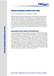
1.1 <strong>Starting</strong> the software<br />
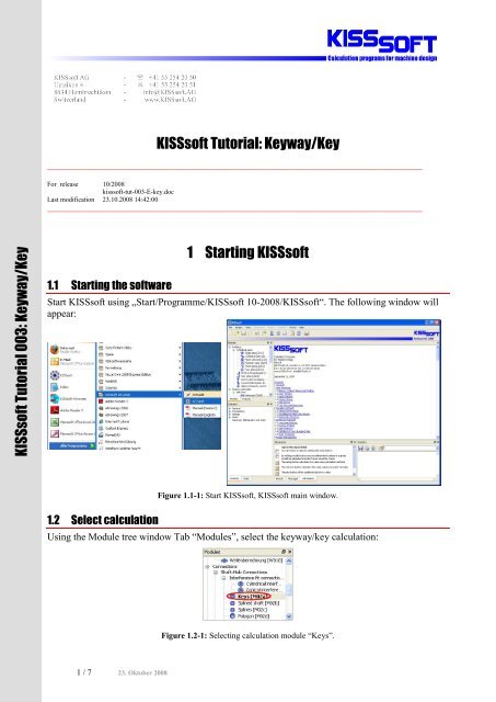
1 <strong>Starting</strong> <strong>K<strong>ISSsoft</strong></strong><br />
Start <strong>K<strong>ISSsoft</strong></strong> using „Start/Programme/<strong>K<strong>ISSsoft</strong></strong> 10-2008/<strong>K<strong>ISSsoft</strong></strong>“. The following window will<br />
appear:<br />
1.2 Select calculation<br />
Figure 1.1-1: Start <strong>K<strong>ISSsoft</strong></strong>, <strong>K<strong>ISSsoft</strong></strong> main window.<br />
Using the Module tree window Tab “Modules”, select the keyway/key calculation:<br />
Figure 1.2-1: Selecting calculation module “<strong>Key</strong>s”.<br />
1 / 7 23. Oktober 2008
2.1 Task<br />
2 Analysis of a key<br />
A key is to be analysed with the following key/load data (see DIN 6892, example 1):<br />
Shaft diameter<br />
120mm<br />
Outer diameter hub D1 200mm*<br />
Outer diameter D2<br />
270mm<br />
Width for diameter D2<br />
within the carrying length, c 17mm<br />
Distance a0<br />
96mm<br />
<strong>Key</strong><br />
DIN 6885.1 A32x18x125<br />
No. of keys 1<br />
Chamfer shaft<br />
None<br />
Chamfer hub<br />
0.8mm<br />
Nominal torque<br />
4’000Nm<br />
Maximal torque<br />
15’000Nm<br />
Application factor 1.50<br />
Frequency of peak load 10’000<br />
Frequency of change in sense<br />
of rotation 250’000<br />
Slowly alternating torque,<br />
Material hub<br />
GG25<br />
Material key<br />
C45<br />
Material shaft<br />
C60<br />
Carrying length ltr<br />
125-32=93mm<br />
* Since ther are 10 holes in part 1 (64mm diameter) to accommodate the elastic elements of the<br />
coupling, the hub is less stiff under torsion. Hence, for the calculation, the pitch diameter is used<br />
and not the outer diameter of the hub.<br />
There are two analysis methods available in <strong>K<strong>ISSsoft</strong></strong> for keys:<br />
- DIN 6892, Method C<br />
- DIN 6892, Method B<br />
Method C according to the DIN standard is a simplified method and will not be considered here.<br />
Hence, DIN 6892, method B should be selected under the “Module specific settings” after starting<br />
the module:<br />
Figure 2.1-1: Selecting, DIN 6892, method B as analysis method.<br />
The following material properties are to be used:<br />
Yield strength Re [MPa]<br />
Ultimate strength Rm [MPa]<br />
EN-GJL-250 (GG25 brittle) 130 200<br />
C45 K (cold drawn) 430 680<br />
1C60 N (normalised) 310 600<br />
2 / 7
Figure 2.1-2: Assembly of the connection, with the left half of the connection to be analysed.<br />
2.2 Entering the data<br />
This data is to be entered as follows:<br />
Figure 2.1-3: Definition of D2, D1, a0 and c.<br />
3 / 7
Important:<br />
Selection of<br />
calculation method<br />
<strong>Key</strong> form to be<br />
selected, details of<br />
geometry are<br />
defined<br />
automatically with<br />
the shaft diameter,<br />
see Figure 2.2-3.<br />
Choose „Own<br />
Input“ for the<br />
materials, see also<br />
Figure 2.2-4<br />
Figure 2.2-1: Input window - Definition of loads and main dimensions.<br />
The detailed geometry as shown in Figure 2.1-2 is to be entered as follows:<br />
Figure 2.2-2: Input window, group: ‘geometry’ - Definition of geometry of hub with different outer diameters.<br />
The value for width of outer diameter D2 over in the carrying length c, can be specified by the<br />
setting the flag in the “Checkbox” for this.<br />
The geometry of the key is shown using the “Plus button”, see marking in Figure 2.2-2:<br />
The detailed geometry of the key is defined from the<br />
type of key selected and the shaft diameter. It is also<br />
possible to define own key geometry.<br />
Figure 2.2-3: Information on the key selected.<br />
The material data has to be defined using the “Plus button” to the right of the selection list (Select<br />
“Own Input” first).<br />
4 / 7
Definition of key material. Define<br />
ultimate and yield strength. The value<br />
for the permissible pressure is only<br />
relevant for the calculation method<br />
according to Niemann.<br />
Material type is to be chosen correctly.<br />
Since this is a brittle material, the<br />
permissible stresses will be calculated<br />
based on the ultimate strength of the<br />
material and not on the yield strength.<br />
Definition of shaft material<br />
2.3 Execution of analysis and protocol<br />
Figure 2.2-4: Defining the materials.<br />
Pressing in the Tool bar the icon “Ó” (or the button F5) in the main window starts the calculation<br />
and some results are shown in the lower section of the main window (such as resulting pressures<br />
and safety factors). Note the status bar shows “Results are consistent”. This shows that the input<br />
data and the results shown correspond.<br />
The analysis of the key is according to DIN 6892. The calculation is especially suitable for static<br />
loads, but also for pulsating and alternating loads. However, usually the shaft is the critical element<br />
of the connection. The shaft has to be checked in the shaft analysis, see section 3.<br />
Using <strong>K<strong>ISSsoft</strong></strong>, the load carrying length of the key is always used as the load carrying length<br />
(ltr=93 mm). The frictional torque has to be calculated in another module (e.g. in the interference fit<br />
module). If it is not known, it should be set to zero. The safety factors shown are the minimal safety<br />
due to nominal torque (fatigue strength) and peak torque (static strength). Note that the application<br />
factor is used only for the nominal load.<br />
Using in the Tool bar the icon to the right of “Ó” (or F6) a report containing all input data, analysis<br />
parameters, and results is written. This report includes all input data, analysis parameters (see also<br />
section 2.5) and results. It can easily be included in a formal strength report.<br />
5 / 7
2.4 Calculation of maximum permissible torque<br />
In a second step, the permissible nominal torque is to be calculated such that a minimal safety factor<br />
of 1.20 is reached. For this, the required safety factor of 1.20 is defined in the module specific<br />
settings, (see Figure 2.4-1). Then, the “Sizing button” to the right of the nominal torque field is to<br />
be pressed and the maximum permissible nominal torque is calculated to be 3305Nm. If then “Ó” is<br />
pressed again, the resulting minimal safety factor will be 1.20, see marking in Figure 2.4-2.<br />
Figure 2.4-1: Set the required safety factor in the module specific settings.<br />
2<br />
1<br />
(1)By Pressing the<br />
“sizing button” the<br />
result is for<br />
permissible<br />
nominal torque is<br />
shown.<br />
(2) After<br />
recalculation<br />
results in safety<br />
factor being equal<br />
to the required<br />
safety factor (3).<br />
3<br />
2.5 Remarks on the report<br />
Figure 2.4-2: Calculation of maximum permissible nominal torque.<br />
Some remarks on the parameters listed in the report:<br />
- Equivalent torque: Teq=KA*Tnenn , KA according to DIN3990<br />
- Circumferential force from torque: Feq=Teq/r , Fmax=Tmax/r<br />
- Definition of load carrying length, ltr and depth, ttr<br />
- Pressure from circumferential force, contact area and load factor Kv: depending on number<br />
of keys used; maximum of two keys accepted in analysis, Kv=0.75 (higher for pressure<br />
under peak load (deformation of key assumed), Kv=0.9)<br />
- Load distribution coefficient K l , uneven load distribution over the length of the key<br />
6 / 7
- Friction factor K R : Accounts for torque transmitted by means of interference fit (for peak<br />
torque only)<br />
- Do not use brittle materials for hubs if using interference fit<br />
- Load direction changes coefficient f W : considers the frequency of changes in load direction,<br />
different for abrupt or slow changes<br />
- Frequency of peak load factor f L : factor considering the frequency of peak loads, different<br />
for brittle or ductile materials<br />
- Support factor f S : Higher strength of materials loaded under pressure, depending on material<br />
- Hardness influence coefficient f H : for hardened surfaces<br />
- Permissible contact stress calculated from ultimate (brittle materials) or yield strength<br />
(ductile materials) and above factors<br />
- For temperature range of -40°C to 150°C<br />
3 Shaft analysis<br />
3.1 General<br />
From the research conducted on keys, it is known that usually it is the shaft which is the critical part<br />
of the connection. Shearing of the key is uncommon and happens only under peak loads. The<br />
corrosion effects shown in a number of fatigue tests due to alternating bending action (and resulting<br />
micro movement between the members of the connection) is known to be the prime damaging<br />
mechanism in the connection. The complete proof of strength of the connection not only includes<br />
the proof against permissible contact stresses as shown above, but also the proof of strength of the<br />
shaft and the hub. However, the latter rarely is a problem except for very thin-walled hubs. In the<br />
<strong>K<strong>ISSsoft</strong></strong> key analysis, proof is only carried out for contact stresses. The proof against fatigue<br />
failure of the shaft should be obtained using the <strong>K<strong>ISSsoft</strong></strong> shaft analysis.<br />
3.2 Notch factors for shaft analysis<br />
Since the damaging mechanism (especially for the shaft) is a combination of notch stresses and<br />
corrosion, it is not sufficient to use a notched shaft for the determination of notch factors. Hence, for<br />
the determination of notch factors for a key connection, experiments using the complete connection<br />
are necessary. In these experiments, a wide range of parameter has to be investigated. Therefore, the<br />
notch factors given in the literature differ and are usually defined only in a range.<br />
It remains the responsibility of the engineer to carefully review the notch factors used in the shaft<br />
analysis.<br />
See for example<br />
- DIN 6892, Passfedern, Berechnung und Gestaltung<br />
- U. Oldendorf, Lebensdauer von Passfederverbindungen, VDI Bericht 1790<br />
- E. Leidich, Einfluss des Schwingungsverschleisses auf die Tragfähigkeit von Welle-Nabe-<br />
Verbindungen, VDI Bericht 1790<br />
- DIN 743, Tragfähigkeit von Wellen und Achsen<br />
7 / 7