KISSsys application: Lifetime analysis of a 4MW wind turbine gearbox
KISSsys application: Lifetime analysis of a 4MW wind turbine gearbox
KISSsys application: Lifetime analysis of a 4MW wind turbine gearbox

You also want an ePaper? Increase the reach of your titles
YUMPU automatically turns print PDFs into web optimized ePapers that Google loves.
<strong>Lifetime</strong> <strong>analysis</strong> <strong>of</strong> a <strong>wind</strong> <strong>turbine</strong> <strong>gearbox</strong> using <strong>KISSsys</strong><br />
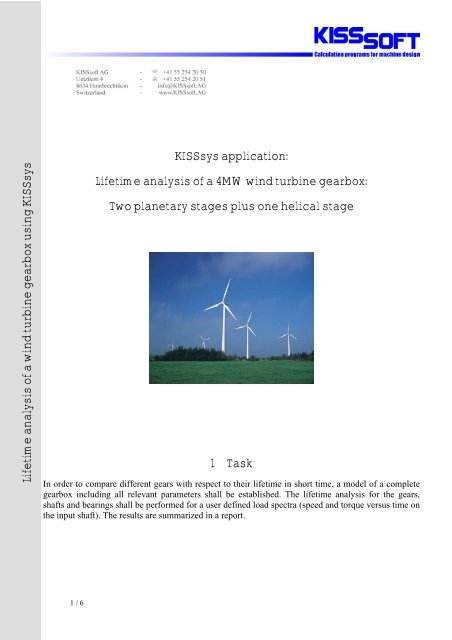
<strong>KISSsys</strong> <strong>application</strong>:<br />
<strong>Lifetime</strong> <strong>analysis</strong> <strong>of</strong> a <strong>4MW</strong> <strong>wind</strong> <strong>turbine</strong> <strong>gearbox</strong>:<br />
Two planetary stages plus one helical stage<br />
1 Task<br />
In order to compare different gears with respect to their lifetime in short time, a model <strong>of</strong> a complete<br />
<strong>gearbox</strong> including all relevant parameters shall be established. The lifetime <strong>analysis</strong> for the gears,<br />
shafts and bearings shall be performed for a user defined load spectra (speed and torque versus time on<br />
the input shaft). The results are summarized in a report.<br />
1 / 6
2 Solution<br />
Using <strong>KISSsys</strong> the complete <strong>gearbox</strong>, consisting <strong>of</strong> two planetary stages and one helical stage is<br />
modeled. Hence, the kinematics <strong>of</strong> the epicyclic gear is known and the loads on the gears, bearings and<br />
shafts can be calculated automatically. Using these loads, the lifetime <strong>of</strong> the mechanical elements is<br />
automatically calculated using KISSs<strong>of</strong>t in the background.<br />
It is hence sufficient to define the speed and torque acting on the input shaft in order to analyze all<br />
mechanical elements present.<br />
The lifetime <strong>analysis</strong> <strong>of</strong> the elements is performed in <strong>KISSsys</strong> using a damage accumulation algorithm.<br />
Calculating a damage equivalent load based on the load spectrum is not meaningful in this <strong>application</strong><br />
since the slope <strong>of</strong> the S-N curve <strong>of</strong> the bearings and gears is not equal. The load spectra can either be<br />
defined manually or read from a text file.<br />
Since all <strong>analysis</strong> parameters and results are stored in variables, comprehensive reports can be<br />
generated.<br />
3 Description <strong>of</strong> the model<br />
3.1 Structure <strong>of</strong> the <strong>gearbox</strong><br />
The <strong>gearbox</strong> consists <strong>of</strong> two planetary stages and one helical stage.<br />
Technical data <strong>of</strong> the <strong>gearbox</strong> (approximate):<br />
Power rating<br />
<strong>4MW</strong><br />
Nominal torque<br />
2500kNm<br />
Nominal speed<br />
15Upm<br />
Reduction 1:120<br />
Diameter<br />
2000mm<br />
Length<br />
2800mm<br />
<strong>Lifetime</strong> required 20years<br />
2 / 6
Figure 3.1-1 Structure <strong>of</strong> the <strong>gearbox</strong>: Black: shafts, blue: gears, Yellow: bearings, red: couplings. Note that only<br />
one planet per stage is shown.<br />
The two rings <strong>of</strong> the planetary stages are fixed, the first stage has five, the second three planets (only<br />
one planet is shown in the 3D view). The constraint <strong>of</strong> the rings is modeled in <strong>KISSsys</strong> by setting the<br />
rotational speed to zero. The power flow <strong>of</strong> the gear box is shown below:<br />
Figure 3.1-2 Schematic <strong>of</strong> the <strong>gearbox</strong> with power flow (or forces) (red), mechanical elements (shafts, gears,<br />
couplings, bearings) (black) and power input and output.<br />
3 / 6
The three dimensional representation and schematic shown above are based on a tree structure shown<br />
below:<br />
Figure 3.1-3 Tree structure <strong>of</strong> the <strong>gearbox</strong> consisting <strong>of</strong> several shafts, power input<br />
and output and connections. For the sun shaft <strong>of</strong> the second stage, the elements<br />
arranged on the shaft (bearings and gears) are shown.<br />
3.2 Definition <strong>of</strong> forces acting<br />
The user sets the nominal speed and torque on the input shaft (rotor hub)<br />
using the following dialog:<br />
Figure 3.2-1 Dialog for definition <strong>of</strong> input (or output) speed and input (or output) torque<br />
These nominal values can be modified using a load spectrum (frequency, torque and speed). The load<br />
spectrum can be defined manually or read from a text file. The spectrum again is selected / defined<br />
using the following dialog:<br />
Figure 3.2-2 Selection <strong>of</strong> the applicable load spectrum through a<br />
<strong>KISSsys</strong> dialog and <strong>wind</strong>ows open file dialog<br />
The load spectrum is then read and stored in <strong>KISSsys</strong> as<br />
a table:<br />
Figure 3.2-3 Load spectrum read in <strong>KISSsys</strong>. The speed<br />
remains constant on the nominal value. The left column shows<br />
the frequencies (sum <strong>of</strong> all frequencies=1), middle column<br />
shows the relative torque<br />
4 / 6
Furthermore, the user can define lubrication parameters such as lubrication mode, lubricant and<br />
lubricant temperature:<br />
Figure 3.2-4 Selection <strong>of</strong> lubricant, temperature and lubrication mode<br />
3.3 Execution <strong>of</strong> <strong>analysis</strong>, summary <strong>of</strong> results<br />
In the user interface (see below) after having defined the loads, spectrum and lubrication, the user can<br />
start the lifetime calculation on calling the function „Calc. <strong>Lifetime</strong>“.<br />
Figure 3.3-1 Overview <strong>of</strong> the <strong>KISSsys</strong> interfaces (user interface: large table in top right corner)<br />
This function calculates for each step <strong>of</strong> the load spectrum a damage for all mechanical elements<br />
present using the respective S-N curves (which are all different for all parts). The damage is<br />
accumulated continually and being transformed into a lifetime at the end <strong>of</strong> the <strong>analysis</strong>. The <strong>analysis</strong><br />
<strong>of</strong> the gears is according to DIN, ISO or AGMA standards, the <strong>analysis</strong> <strong>of</strong> the bearings according to<br />
standard L10 calculation or DIN/ISO 281.<br />
The tooth geometries can be modified and optimized through calling the respective KISSs<strong>of</strong>t<br />
interfaces.<br />
Analysis <strong>of</strong> a <strong>gearbox</strong> with modified tooth data takes a few seconds only.<br />
5 / 6
Figure 3.3-2 Optimization <strong>of</strong> tooth form using KISSs<strong>of</strong>t, automatic exchange <strong>of</strong> data between KISSs<strong>of</strong>t and <strong>KISSsys</strong><br />
ensures that the <strong>analysis</strong> <strong>of</strong> the <strong>gearbox</strong> uses the correct tooth geometry.<br />
4 Conclusion<br />
The great advantage <strong>of</strong> this systematic approach to <strong>gearbox</strong> <strong>analysis</strong> is the gain in time when<br />
comparing different gear designs or when performing parametric studies.<br />
While the modeling <strong>of</strong> such a system does require time and knowledge <strong>of</strong> the s<strong>of</strong>tware, the time saved<br />
afterwards when optimizing the gears and for reporting is great, especially if the <strong>analysis</strong> is to be<br />
performed for load collectives with a high number <strong>of</strong> steps.<br />
The reporting functions delivering comprehensive reports for all members analyzed helps a lot when<br />
documenting the <strong>analysis</strong> and the design <strong>of</strong> the <strong>gearbox</strong> respectively. The not so well liked work <strong>of</strong><br />
writing <strong>analysis</strong> reports is accelerated considerably.<br />
The model shown above can be extended to other epicyclic gears. A possible next step would be to<br />
introduce additional forces and bending moments on the input shaft, greatly affecting the bearings<br />
lifetime.<br />
6 / 6