Wire Harness Installation Instructions - Painless Performance
Wire Harness Installation Instructions - Painless Performance
Wire Harness Installation Instructions - Painless Performance
You also want an ePaper? Increase the reach of your titles
YUMPU automatically turns print PDFs into web optimized ePapers that Google loves.
<strong>Wire</strong> <strong>Harness</strong> <strong>Installation</strong> <strong>Instructions</strong><br />
For Installing:<br />
Part # 30715<br />
1970-1981 Camaro Power Window/Power Door Lock <strong>Harness</strong><br />
Perfect <strong>Performance</strong> Products, LLC<br />
<strong>Painless</strong> <strong>Performance</strong> Products Division<br />
2501 Ludelle Street<br />
Fort Worth, TX 76105-1036<br />
800-423-9696 phone – 817-244-4024 fax<br />
Web Site: www.painlessperformance.com<br />
E-Mail: painless@painlessperformance.com
If you have any questions concerning the installation of this harness or having trouble in general, feel free<br />
to call <strong>Painless</strong> <strong>Performance</strong> Products' tech line at 1-800-423-9696. Calls are answered from 8am to 5pm<br />
central time, Monday thru Thursday and 8am-4:30pm Friday, except holidays.<br />
We have attempted to provide you with as accurate instructions as possible, and are always concerned<br />
about corrections or improvements that can be made. If you have found any errors or omissions, or if you<br />
simply have comments or suggestions concerning these instructions, please write us at the address<br />
above, send us a fax at (817) 244-4024 or e-mail us at painless@painlessperformance.com. We sincerely<br />
appreciate your business.<br />
Perfect <strong>Performance</strong> Products, LLC shall in no event be liable in contract or tort (including negligence)<br />
for special, indirect, incidental, or consequential damages, such as but not limited to, loss of property<br />
damage, or any other damages, costs or expenses which might be claimed as the result of the use or<br />
failure of the goods sold hereby, except only the cost of repair or replacement.<br />
Before any installation takes place disconnect the battery<br />
Preparation<br />
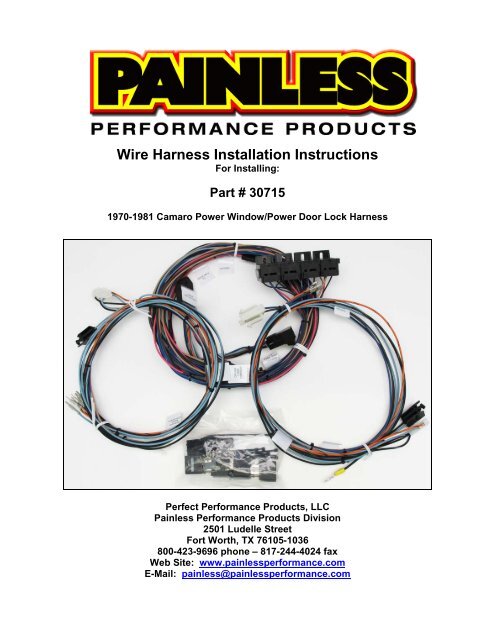
Examine all the parts included with the kit. They are (as seen on the front cover):<br />
• Driver Door <strong>Harness</strong><br />
• Passenger Door <strong>Harness</strong><br />
• Main harness, this will have relay bases pre-installed on it<br />
Bag kit containing:<br />
4 relays, 4 self tapping screws, strips of velcro, 2 large 8 pin<br />
connectors and terminals position locks, 2 white connectors and 4<br />
larger un-insulated terminals, umbrella zip ties and small 4” zip ties<br />
Prior to any harness or connector installation, you must prep the two supplied<br />
door harnesses. This involves inserting the door grommets onto the harness and<br />
installing the two large 8 pin connectors from the bag kit. The factory door grommets<br />
MUST be re-used as the factory style door grommet is no longer available.<br />
This grommet each door harness requires will protect the door harness from the<br />
three holes the harness passes through to get into the interior of the car. One hole is in<br />
the door itself, the next in the body/door jamb (behind the door jamb switch/below the<br />
top hinge), the third and smallest hole is on the inner structure panel the kick panel<br />
fastens to.<br />
2
Begin by wrapping tape around the terminal end of both the Driver Door <strong>Harness</strong><br />
and the Passenger Door <strong>Harness</strong>. Tape isn’t absolutely necessary but it does<br />
make installation of the grommet a lot easier.<br />
Insert the taped/terminal end of each door harness through the big end of the<br />
grommet until it emerges from the small end, as seen below.<br />
With the grommets now installed on both door harnesses, the connectors can be<br />
installed on the door harnesses. This will be the two large 8 pin connectors supplied in<br />
the parts kit, along with the terminal position lock(s) that go with each connector. Use<br />
the following pictures along with the pin out diagram to identify the correct connector for<br />
each harness and pin it out. Please take notice that the connectors, along with the<br />
terminals on the door harnesses, are different. This is to avoid being able to incorrectly<br />
plug in the wrong door harness to the main harness.<br />
This is the Driver Side Door <strong>Harness</strong>, above. It will require the smaller of the 8<br />
pin connectors and also uses the 2 blue terminal position locks.<br />
Use the diagram above to carefully insert the terminals on the driver side door<br />
harness into this connector. Make certain you pin this connector out correctly.<br />
Once all terminals have been inserted into the connector install the 2 terminal<br />
position locks in place.<br />
3
This is the Passenger Side Door <strong>Harness</strong>, above. It will require the larger of the 8<br />
pin connectors and also uses the gray terminal position lock.<br />
Use the diagram above to carefully insert the terminals on the Passenger Side<br />
Door <strong>Harness</strong> into this connector.<br />
The driver side and passenger side kick panels, door panels, and driver side<br />
door sill plate must be removed before any installation. The center console will also<br />
need to the loosened from all of its mounting points as well, but it may remain in the<br />
vehicle.<br />
Door <strong>Harness</strong> <strong>Installation</strong><br />
<strong>Installation</strong> of the door harnesses will require the window to be in the up position.<br />
This will give you access to all of the components and to the harness routing channel.<br />
<strong>Installation</strong> of the door harnesses will consist of two parts: Door Grommet<br />
<strong>Installation</strong>, and Door <strong>Harness</strong> Connections to the components in the door. The<br />
following steps will outline these procedures.<br />
Door Grommet <strong>Installation</strong><br />
Begin by placing the harness in the door, with the 8 pin connector you just<br />
installed towards the front of the car.<br />
Pass the 8 pin connector through the large hole in the door, and then<br />
through the smaller hole in the door jamb area into the interior of the car.<br />
4
Pull the grommet through<br />
the hole in the door, and<br />
feed it into the inside of the<br />
car until the grommet<br />
matching the hole in the<br />
body is through the door,<br />
seen on page 2. You will<br />
seat the grommet into the<br />
car body (door jamb). A flat<br />
head screw driver will make<br />
it easier to get the grommet<br />
seated.<br />
You will next seat the big<br />
end of the grommet into the<br />
door. This is done by pulling<br />
the entire grommet through<br />
the hole and then reinserting<br />
from the jamb side<br />
back into the door, as shown<br />
below.<br />
Once the door grommet is<br />
installed, go to the kick panel<br />
area where the door harness<br />
enters into the inside of the<br />
vehicle. Locate the grommet<br />
and pull it through and seat<br />
the grommet into the small<br />
hole on the interior. All three<br />
seating ridges can be seen<br />
on the door grommet shown<br />
on page 2.<br />
Now that the door harnesses are positioned in the doors, actual component<br />
connections can now take place.<br />
5
Door <strong>Harness</strong> Connections<br />
Window Motor<br />
The window motor connection will have a white 2 pin connector pre-installed,<br />
seen below. This connector will plug directly into the window motor. The window motor<br />
can be accessed through the large hole at the bottom of the door, seen circled in the<br />
photo.<br />
Route the Window Motor connector to the window motor and connect. This<br />
connector will only plug in one way. Be sure to route the wires away from the<br />
regulator and window track to avoid any interference with the operation of the<br />
window.<br />
6
Lock Actuator<br />
The lock actuator will have a black 2 pin connector<br />
pre-installed. The wires will provide power and ground to<br />
the actuator based on what position the lock switch is in.<br />
Begin by locating the channel inside the door that the<br />
lock actuator wires run along to protect them from<br />
the movement of the window.<br />
Route the two wires down this channel towards the rear of the door. There may<br />
be factory clips along the top of this channel for you to attach the harness to.<br />
If the factory clips are not present, “umbrella” style zip ties have been provided.<br />
These will fit the ¼” holes left behind by the factory clips. To make it easier to<br />
install these zip ties. Create a loop, seen below, before installing the zip tie into<br />
the hole in the channel. Make sure there is enough space in the loop to allow the<br />
connector to pass through. This is easier than trying to thread the zip tie opening<br />
after it has been installed. Do not tighten the zip tie until the wires have been<br />
routed and the connector as been connected.<br />
7
With the wires now routed down the length of the door, connection to the lock<br />
actuator can take place. In order to plug the connector into the actuator, the tab<br />
on the connector must be pressed down while the connector is being plugged<br />
into the actuator. This will raise the locking tab to allow it to fit over the<br />
connection point. Once connected go back and tighten any zip ties that may have<br />
been installed in the channel.<br />
If you find that your actuator(s) are faulty or simply missing, they can be replaced<br />
by using ACDelco part # 22020256<br />
Lock switch<br />
The lock switch will have a “squarish” white 5 pin connector pre-installed. The<br />
driver side will have a ground connection, were as the passenger side will not. All of the<br />
power and ground signals from the driver side lock switch will go though the passenger<br />
side switch and then to the lock actuator in each door. In other words, the lock function<br />
of both doors will only work if the passenger side switch is in working order.<br />
8
Begin by routing the lock switch connector and wires through the square opening<br />
towards the front of the door. This will be the opening in front of the opening you<br />
used to make the window motor connection. Route these wires following the path<br />
shown in the photo below. If your door no longer has the factory harness clips,<br />
umbrella type zip ties have been provided that will snap into the ¼” holes left<br />
behind by the clips.<br />
The driver side lock switch will have a wire with a ring terminal pre-installed. This<br />
wire is a ground and will be fastened to the door, seen in the photo above. The<br />
passenger side lock switch does not require this ground.<br />
To ensure the switch locks when the switch is pressed down, and unlocks when<br />
the switch is pressed up, make sure the switch is positioned in the door panel<br />
with the single pin (seen on the back of the switch) down towards the door<br />
handle, as shown is the photos on the next page.<br />
With the lock switch wires now routed properly, the door panel can now be lifted<br />
up to the lock switch connector, and the connector installed onto the switch.<br />
Please be aware that this style of connector fits very tight onto<br />
the switch and can be difficult to remove from the switch once<br />
installed. Do not plug this connector in until you are ready to<br />
install the door panel and do not let the door panel hang from<br />
this connection.<br />
A replacement lock switch for both doors can be found at most<br />
auto parts stores under Doorman part number 49241. This may be<br />
confusing to most as this switch is labeled as a “Power Window<br />
Switch”, but this is the switch used for lock function on the second<br />
gen Camaro. A factory retaining ring, from the original switch or sold<br />
through original component sources, will also be needed to mount<br />
this switch in the door panel. An example of this retaining ring, the<br />
installation of the ring, and the proper placement of the switch can be<br />
seen on the following page.<br />
9
The trim ring has four tabs that bend over to hold the switch onto the<br />
panel. This ring simply snaps down over the black retaining tabs on the<br />
side of the lock switch.<br />
Once the ring is installed, the switch can then be placed in the door panel.<br />
Be sure to position the single pin towards the door handle and the paired<br />
pins up towards the top on the panel. When the switch is installed on the<br />
panel, bend the four tabs over to secure the switch.<br />
At this time both Door <strong>Harness</strong>es should be installed<br />
10
MAIN HARNESS CONNECTION<br />
The main harness provides power connections for the lock switches as well as<br />
the window motor relays, the console mounted power window switch, and a connector<br />
that will fit each of the connectors you installed onto the door harness.<br />
Door <strong>Harness</strong> Connectors<br />
Plugging in the door harnesses connectors first will help position the main<br />
harness inside the vehicle.<br />
Plug the connector labeled “TO DRIVER<br />
DOOR HARNESS” into the door harness<br />
connector you previously installed. This<br />
will be in the driver side kick panel area.<br />
Route the connector labeled “TO PASS. DOOR<br />
HARNESS” over to the passenger side. You<br />
may have to remove the gauge cluster, a/c<br />
heater switch panel, and or radio in order to<br />
have access to a direct path all the way across<br />
the vehicle (behind the dash). Remember to<br />
keep the wires away from sharp edges and use<br />
the small 4” zip ties to secure the harness along<br />
its routing path. Do not tighten the zip ties until<br />
the connector has been connected.<br />
Once you have the connector over to the<br />
passenger side, connect this connector to the<br />
connector you previously installed on the<br />
passenger side door harness.<br />
Power Connections<br />
The power connections will consist of two<br />
wires with single pin connectors pre-installed.<br />
These two wires will be grouped together with a<br />
label reading “TO FUSE BLOCK”. The pink wire<br />
will provide a power source to the power window<br />
relays. The orange wire will provide power to the<br />
lock switch.<br />
Connection of these two connectors will depend on what chassis harness you<br />
currently have installed in your vehicle. From the following groups of instructions,<br />
choose the application that best fits with the style of fuse block you have:<br />
11
‣ 18 circuit <strong>Painless</strong> 2 nd Generation Camaro <strong>Harness</strong><br />
The two connectors labeled “TO FUSE BLOCK” on this power window/lock<br />
harness will plug directly into any one of the three 2 nd Gen. specific harnesses <strong>Painless</strong><br />
offers. These harnesses are 20112, 20113, and 20114.<br />
These chassis harnesses have two connectors labeled<br />
“POWER WINDOW” and “POWER LOCK” pre-installed, seen to<br />
the right. The pink/black wire labeled “POWER WINDOW” will<br />
connect to the pink wire found on this power window/lock harness.<br />
The orange/black wire labeled “POWER LOCK” will connect to the<br />
orange wire of this power window/lock harness.<br />
‣ <strong>Painless</strong> or other aftermarket Universal <strong>Harness</strong><br />
Connectors have been provided with this power<br />
window/lock harness to allow you to make a plug and play<br />
connection without having to hardwire anything directly to the<br />
chassis harness.<br />
If you are using an 18 circuit aftermarket universal<br />
harness, chances are there are provisions in the harness for<br />
power window and power lock. Most harnesses will provide<br />
power widow power and power lock power to both doors; you will only be using one of<br />
the power window wires (#911 on a <strong>Painless</strong> harness) and one of the power lock wires<br />
(#910 on a <strong>Painless</strong> harness).<br />
For those that do not have circuits in the chassis harness predestined for power<br />
window and/or power lock functions, 30 amp switched ignition power and 30 amp<br />
battery constant power will need to be sourced.<br />
The orange wire found on this power window/lock harness is intended to connect to<br />
a constant battery power source. This will be a power source that has power at all<br />
times.<br />
The pink wire found on this power window/lock harness is intended to connect to a<br />
switched ignition power source. This will be a power source that only has power when<br />
the ignition switch is in the ON position.<br />
Route the wires that will provide these two<br />
power sources to the inline connector found<br />
on this power window/lock harness.<br />
Strip ¼” of insulation and crimp the supplied<br />
terminals onto each wire. These are tough<br />
terminals to crimp and a pair of roll over<br />
crimpers like <strong>Painless</strong> part number 70900 is<br />
highly recommended.<br />
12
Once the terminals are installed, insert the terminal and wire into the supplied<br />
connectors, seen on the previous page, and plug the power connections from the<br />
new power window/lock harness into the connectors you have just installed.<br />
‣ Factory Chassis <strong>Harness</strong><br />
Those still using a factory fuse block, or a factory reproduction harness, connection<br />
of this new power window/lock harness is as easy as plugging the connectors labeled<br />
“TO FUSE BLOCK” into the appropriate accessory port in the middle of the fuse block.<br />
The accessory ports are clearly labeled as to what type of power they provide:<br />
BAT. Is battery power, this is what<br />
the orange wire found on this harness<br />
requires for door lock function. Plug<br />
this connector into the BAT<br />
accessory port. If your vehicle was a<br />
factory equipped power window/lock<br />
car, you will have an accessory tab<br />
above the BAT port that this<br />
connector will plug into; this port is<br />
empty in the photo to the right.<br />
IGN. And ACC will both have<br />
switched ignition power, this is what<br />
the pink wire requires to power all<br />
four up/down window motor relays. If<br />
you want the windows to work when<br />
the key is in the ACCESSORY position, plug the connector into the ACC port.<br />
For the windows to only work in the ON position, plug the connector into the IGN<br />
port.<br />
13
Ground<br />
The wire labeled “GROUND” will provide a ground source for the relays for<br />
proper activation. This wire will have a ring terminal pre-installed.<br />
Using the self tapping screw in the parts kit, connect this wire to a good clean<br />
ground source, like the brace behind the gauge cluster as shown in the picture<br />
below.<br />
Window Switch and Relays<br />
A long length of wires is all that is left on the main harness. This group of wire will<br />
contain the four relays, linked together to form a relay bank, and the connection to the<br />
window switch. This group of wire will need to be routed down the door sill channel and<br />
over to the console. For proper routing the driver side seat will need to be removed.<br />
Remove the door sill plate to gain access to the channel the wires will need to<br />
route down. This channel will also have the wires of the chassis harness for the<br />
tail section (turn, tail, dome light, fuel sender).This channel also has a cover over<br />
it under the sill plate that will need to be removed as well.<br />
Route the wires for the relay bank and window switch down the channel to the<br />
notch that allows routing the wires towards the interior of the car, about half way<br />
down the channel.<br />
14
Route the wires through the notch to the center of the car.<br />
If you are not using any type or wire loom or wrap, like <strong>Painless</strong> PowerBraid or<br />
ClassicBraid, wrap electrical tape around the wires where they pass through from<br />
the channel. This will help keep any rubbing that may occur from damaging the<br />
wire insulation.<br />
Route the window switch connector to the console mounted window switch and<br />
connect. To ensure the driver side switch operates the driver side window, the<br />
wires going into the connector must be on the driver side of the console.<br />
If a replacement window switch is needed<br />
GM #1725092 can be used to help you locate one<br />
new or reproduced from online sources/auctions or<br />
numerous fbody part vendors.<br />
15
The last part of the install is installing the relays. Installing the relays can be done<br />
one of two ways:<br />
‣ By using the supplied self tapping screws and the tabs on the relay bases to mount<br />
them to the transmission tunnel under the console<br />
To secure the relays to the transmission tunnel/floor board using screws:<br />
Place a screw through the mounting tab at both<br />
ends of the relay bank, as seen in the photo<br />
below.<br />
The bank may be separated by sliding the relay<br />
bases forward if they need to be separated for<br />
extra clearance for mounting, as shown on the<br />
next page.<br />
Once the relay bank has been secured, install<br />
each relay, they will only fit one way.<br />
If the relays ever need to be replaced, they are<br />
standard 40 amp SPST relays sold at most<br />
auto parts stores and can also be bought as<br />
<strong>Painless</strong> part # 80130.<br />
‣ By using the supplied velcro strips to secure them to the underside of the console.<br />
To secure the relays to the console using velcro:<br />
Locate the four strips of velcro provided with this kit.<br />
Pull the backing off 2 strips and place them on the<br />
back of the relay bank.<br />
The bank may be separated by sliding the relay<br />
bases forward if they need to be separated for extra clearance for mounting. The<br />
velcro adhesive is very strong, once the velcro is applied do not try to peel it off,<br />
this will ruin the piece.<br />
16
Fasten the two remaining pieces of<br />
velcro to the pieces that were just<br />
installed on the relay bases. The picture<br />
to the right will help clarify this. This will<br />
allow you to precisely place the velcro<br />
and relay bases to a mounting surface<br />
of the console.<br />
Clean the area you plan to stick the<br />
velcro to. As stated before, you only get<br />
one shot at getting the velco to stick<br />
correctly.<br />
Install each relay into the relay bank,<br />
they will only fit one way.<br />
If the relays ever need to be replaced,<br />
they are standard 40 amp SPST relays<br />
sold at most auto parts stores and can<br />
also be bought as <strong>Painless</strong> part #<br />
80130.<br />
Peel the backing off the remaining 2<br />
pieces of velcro and stick the relays<br />
bases to the underneath side of the<br />
console.<br />
At this point the new harness is completely installed. Before components like the driver<br />
side seat, door sill and kick panels are installed you should test that everything is<br />
working.<br />
Reconnect the battery<br />
Test the door lock function<br />
Before checking the power window function, <strong>Painless</strong> recommends the track for<br />
the windows be cleaned and re-greased to ensure the window moves up and<br />
down freely.<br />
Once everything is tested, components that were removed for installation can<br />
now be re-installed.<br />
17
NOTES<br />
18


