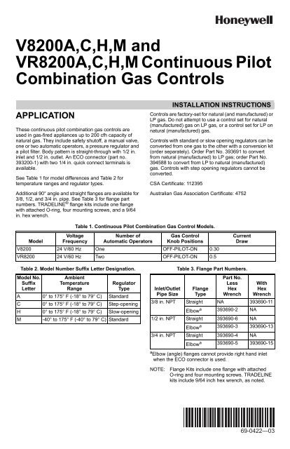
69-0422—03 - V8200A,C,H,M and VR8200A,C,H,M Continuous
69-0422—03 - V8200A,C,H,M and VR8200A,C,H,M Continuous
69-0422—03 - V8200A,C,H,M and VR8200A,C,H,M Continuous

You also want an ePaper? Increase the reach of your titles
YUMPU automatically turns print PDFs into web optimized ePapers that Google loves.
<strong>V8200A</strong>,C,H,M <strong>and</strong><br />
<strong>VR8200A</strong>,C,H,M <strong>Continuous</strong> Pilot<br />
Combination Gas Controls<br />
APPLICATION<br />
These continuous pilot combination gas controls are<br />
used in gas-fired appliances up to 200 cfh capacity of<br />
natural gas. They include safety shutoff, a manual valve,<br />
one or two automatic operators, a pressure regulator <strong>and</strong><br />
a pilot filter. Body pattern is straight-through with 1/2 in.<br />
inlet <strong>and</strong> 1/2 in. outlet. An ECO connector (part no.<br />
393200-1) with two 1/4 in. quick connect terminals is<br />
available.<br />
See Table 1 for model differences <strong>and</strong> Table 2 for<br />
temperature ranges <strong>and</strong> regulator types.<br />
Additional 90° angle <strong>and</strong> straight flanges are available for<br />
3/8, 1/2, <strong>and</strong> 3/4 in. pipe. See Table 3 for flange part<br />
numbers. TRADELINE ® flange kits include one flange<br />
with attached O-ring, four mounting screws, <strong>and</strong> a 9/64<br />
in. hex wrench.<br />
INSTALLATION INSTRUCTIONS<br />
Controls are factory-set for natural (<strong>and</strong> manufactured) or<br />
LP gas. Do not attempt to use a control set for natural<br />
(manufactured) gas on LP gas, or a control set for LP on<br />
natural (manufactured) gas.<br />
Controls with st<strong>and</strong>ard or slow opening regulators can be<br />
converted from one gas to the other with a conversion kit<br />
(order separately). Order Part No. 393<strong>69</strong>1 to convert<br />
from natural (manufactured) to LP gas; order Part No.<br />
394588 to convert from LP to natural (manufactured)<br />
gas. Controls with step opening regulators cannot be<br />
converted.<br />
CSA Certificate: 112395<br />
Australian Gas Association Certificate: 4752<br />
Table 1. <strong>Continuous</strong> Pilot Combination Gas Control Models.<br />
Model<br />
Voltage<br />
Frequency<br />
Number of<br />
Automatic Operators<br />
Gas Control<br />
Knob Positions<br />
V8200 24 V/60 Hz One OFF-PILOT-ON 0.30<br />
VR8200 24 V/60 Hz Two OFF-PILOT-ON 0.5<br />
Current<br />
Draw<br />
Table 2. Model Number Suffix Letter Designation.<br />
Model No.<br />
Suffix<br />
Letter<br />
Ambient<br />
Temperature<br />
Range<br />
Regulator<br />
Type<br />
A 0° to 175° F (-18° to 79° C) St<strong>and</strong>ard<br />
C 0° to 175° F (-18° to 79° C) Step-opening<br />
H 0° to 175° F (-18° to 79° C) Slow-opening<br />
M -40° to 175° F (-40° to 79° C) St<strong>and</strong>ard<br />
Inlet/Outlet<br />
Pipe Size<br />
Table 3. Flange Part Numbers.<br />
Flange<br />
Type<br />
Part No.<br />
Less<br />
Hex<br />
Wrench<br />
With<br />
Hex<br />
Wrench<br />
3/8 in. NPT Straight NA 393<strong>69</strong>0-11<br />
a<br />
Elbow 393<strong>69</strong>0-2 NA<br />
1/2 in. NPT Straight 393<strong>69</strong>0-6 NA<br />
a<br />
Elbow 393<strong>69</strong>0-3 393<strong>69</strong>0-13<br />
3/4 in. NPT Straight 393<strong>69</strong>0-4 NA<br />
a<br />
Elbow 393<strong>69</strong>0-5 393<strong>69</strong>0-15<br />
a Elbow (angle) flanges cannot provide right h<strong>and</strong> inlet<br />
when the ECO connector is used.<br />
NOTE: Flange Kits include one flange with attached<br />
O-ring <strong>and</strong> four mounting screws. TRADELINE<br />
kits include 9/64 inch hex wrench, as noted.<br />
<strong>69</strong>-<strong>0422—03</strong>
<strong>V8200A</strong>,C,H,M AND <strong>VR8200A</strong>,C,H,M CONTINUOUS PILOT COMBINATION GAS CONTROLS<br />
INSTALLATION<br />
When Installing This Product...<br />
1. Read these instructions carefully. Failure to follow<br />
them could damage the product or cause a<br />
hazardous condition.<br />
2. Check the ratings given in the instructions <strong>and</strong> on<br />
the product to make sure the product is suitable for<br />
your application.<br />
3. Installer must be a trained, experienced service<br />
technician.<br />
4. After installation is complete, check out product<br />
operation as provided in these instructions.<br />
WARNING<br />
Fire or Explosion Hazard can cause property<br />
damage, severe-injury or death.<br />
Follow these warnings exactly:<br />
1. Disconnect power supply before wiring to<br />
prevent electrical shock or equipment damage.<br />
2. To avoid dangerous accumulation of fuel gas,<br />
turn off gas supply at the appliance service<br />
valve before starting installation, <strong>and</strong> perform<br />
Gas Leak Test after completion of installation.<br />
3. Do not attempt to use a control set for natural<br />
(manufactured) gas on LP gas, or a control set<br />
for LP on natural (manufactured) gas.<br />
4. Do not bend pilot tubing at control or pilot after<br />
compression nut has been tightened, or gas<br />
leakage at the connection may result.<br />
5. Always install sediment trap in gas supply line<br />
to prevent contamination of gas control.<br />
6. Do not force the gas control knob. Use only<br />
your h<strong>and</strong> to push down the reset button or turn<br />
the gas control knob. Never use any tools. If the<br />
knob or reset button will not operate by h<strong>and</strong>,<br />
the control should be replaced by a qualified<br />
service technician. Force or attempted repair<br />
may result in fire or explosion.<br />
CAUTION<br />
Never apply a jumper across or short the valve<br />
coil terminals. This may burn out the heat<br />
anticipator in the thermostat.<br />
Convert between Natural <strong>and</strong> LP<br />
Gas<br />
WARNING<br />
Fire or Explosion Hazard can cause property<br />
damage, severe-injury or death.<br />
Do not attempt to use a control set for natural<br />
(manufactured) gas on LP gas, or a control set<br />
for LP on natural (manufactured) gas.<br />
To convert a control from natural gas to LP gas, or from<br />
LP gas to natural gas, contact your Honeywell ®<br />
representative.<br />
Install Adapters to Control<br />
If adapters are to be installed on the gas control, mount<br />
them as follows:<br />
Flanges:<br />
1. Choose the appropriate flanges for your application.<br />
NOTE: A right angle inlet flange cannot be used with<br />
ECO connected.<br />
2. Remove seal over control inlet or outlet.<br />
3. Check to ensure that the O-ring is fitted in the<br />
groove of flange. If the O-ring is not attached or is<br />
missing, do not use the flange.<br />
4. With O-ring facing valve, line up the screw holes on<br />
the control with the holes in the flange. Insert <strong>and</strong><br />
tighten the screws provided with the flange (See<br />
Fig. 1). Tighten the screws to 25 in.-lbs<br />
(2.8 N·m) of torque to provide a gas-tight seal.<br />
Bushings:<br />
1. Remove seal over control inlet <strong>and</strong> outlet.<br />
2. Apply moderate amount of good quality pipe<br />
compound to bushing, leaving two end threads<br />
bare. On LP installation, use compound resistant to<br />
LP gas. Do NOT use Teflon tape.<br />
3. Insert bushing in control <strong>and</strong> thread pipe carefully<br />
into bushing until tight.<br />
IMPORTANT<br />
These gas controls are shipped with protective<br />
seals over inlet <strong>and</strong> outlet tappings. Do not<br />
remove seals until ready to connect piping.<br />
Follow the appliance manufacturer’s instructions if<br />
available; otherwise, use the instructions provided below<br />
as a guide.<br />
GAS CONTROL OUTLET<br />
FLANGE<br />
9/64 INCH HEX SCREWS (4)<br />
1<br />
1 DO NOT OVERTIGHTEN SCREWS.<br />
TIGHTEN TO 25 INCH-POUNDS.<br />
M2913A<br />
Fig. 1. Fasten Flange to Valve with 25 in.- lbs<br />
(2.8 N·m) Torque.<br />
<strong>69</strong>-<strong>0422—03</strong> 2
<strong>V8200A</strong>,C,H,M AND <strong>VR8200A</strong>,C,H,M CONTINUOUS PILOT COMBINATION GAS CONTROLS<br />
Complete instructions below for piping, installing control,<br />
<strong>and</strong> connecting pilot tubing, thermocouple, <strong>and</strong> wiring.<br />
Make certain the gas leak test you perform on the control<br />
after completing the installation includes leak testing the<br />
adapters <strong>and</strong> screws. If you use a wrench on the valve<br />
after flanges are installed, use the wrench only on the<br />
flange, not the control.<br />
Using Adapters to Solve Swing<br />
Radius Problems<br />
In some field service applications, it is difficult or<br />
impossible to thread the control onto the gas supply pipe<br />
because of space limitations. This problem can be<br />
resolved in many instances through the use of an adapter.<br />
The adapter is installed on the end of the supply pipe in<br />
place of the gas control, following the same precautions<br />
<strong>and</strong> instructions that are used for installing the gas<br />
control. After the adapter is installed, the gas control is<br />
attached to the adapter as outlined above. Note that use<br />
of an adapter increases the overall length of the gas<br />
control.<br />
Location<br />
Do not locate the combination gas control where adverse<br />
environments such as steam cleaning, high humidity or<br />
dipping water, corrosive chemicals, dust or grease<br />
accumulation, or excessive heat are prevalent. To ensure<br />
proper operation, follow these guidelines:<br />
• Locate in a well ventilated area.<br />
• Mount high enough above the cabinet bottom to avoid<br />
exposure to flooding or splashing water.<br />
• Ensure that the ambient temperature does not exceed<br />
the ambient temperature ratings for each component.<br />
• Cover if appliance is cleaned with water, steam, or<br />
chemicals or to avoid dust <strong>and</strong> grease accumulation.<br />
• Avoid locating where exposure to corrosive chemical<br />
fumes or dipping water is likely.<br />
Mount the combination gas manifold. If this is a<br />
replacement application, mount the control in same<br />
location as old control.<br />
HORIZONTAL<br />
3 IN.<br />
(76 MM)<br />
MINIMUM<br />
DROP<br />
DROP<br />
HORIZONTAL<br />
1<br />
PIPED<br />
GAS<br />
SUPPLY<br />
2<br />
GAS<br />
CONTROL<br />
TUBING<br />
GAS<br />
SUPPLY<br />
2<br />
RISER<br />
PIPED<br />
GAS<br />
SUPPLY<br />
3 IN.<br />
(76 MM)<br />
MINIMUM<br />
GAS<br />
CONTROL<br />
Install Piping to Control<br />
All piping must comply with local codes <strong>and</strong> ordinances or<br />
with the Natural Fuel Gas Codes (ANSI Z223.1 NFPA No.<br />
54), whichever applies. Tubing installation must comply<br />
with approved st<strong>and</strong>ards <strong>and</strong> practices.<br />
1. Use new, properly reamed pipe free from chips. If<br />
tubing is used, make sure the ends are square,<br />
deburred <strong>and</strong> clean. All tubing bends must be<br />
smooth <strong>and</strong> without deformation.<br />
2. Run pipe or tubing to the control. If tubing is used,<br />
obtain a tube-to-pipe coupling to connect the tubing<br />
to the control.<br />
3. Install sediment trap in the supply line to the gas<br />
control (See Fig. 2).<br />
Install Control<br />
1. This control can be mounted 0-90 degrees, in any<br />
direction, from the upright position of the gas control<br />
knob, including vertically.<br />
2. Mount the control so gas flow is in the direction of<br />
the arrow on the bottom of the control.<br />
3. Thread pipe the amount shown in Table 4 for<br />
insertion into control. DO NOT THREAD PIPE TOO<br />
FAR. Valve distortion or malfunction may result if<br />
the pipe is inserted too deeply.<br />
Pipe<br />
Size<br />
Table 4. NPT Pipe Thread Length (in.).<br />
Thread Pipe<br />
this Amount<br />
Maximum Depth<br />
Pipe can be<br />
Inserted into<br />
Control<br />
3/8 9/16 3/8<br />
1/2 3/4 1/2<br />
3/4 13/16 3/4<br />
4. Apply a moderate amount of good quality pipe<br />
compound (DO NOT use Teflon tape) to pipe only,<br />
leaving two end threads bare. On LP installations,<br />
use compound resistant to LP gas (See Fig. 3).<br />
5. Remove seals over control inlet <strong>and</strong> outlet, if<br />
necessary.<br />
6. Connect pipe to control inlet <strong>and</strong> outlet. Use wrench<br />
on the square ends of the control. If a flange is<br />
used, place wrench on flange rather than control<br />
(Refer to Fig. 4 <strong>and</strong> 5).<br />
TWO IMPERFECT<br />
THREADS<br />
GAS CONTROL<br />
PIPE<br />
THREAD PIPE THE AMOUNT<br />
SHOWN IN TABLE FOR<br />
INSERTION INTO GAS CONTROL<br />
APPLY A MODERATE AMOUNT OF<br />
PIPE COMPOUND TO PIPE ONLY<br />
(LEAVE TWO END THREADS BARE).<br />
M3075B<br />
Fig. 3. Use of Moderate Amount of Pipe Compound.<br />
RISER<br />
3 IN.<br />
(76 MM)<br />
MINIMUM<br />
GAS<br />
CONTROL<br />
2<br />
1<br />
ALL BENDS IN METALLIC TUBING SHOULD BE SMOOTH.<br />
2 CAUTION: SHUT OFF THE MAIN GAS SUPPLY BEFORE REMOVING<br />
END CAP TO PREVENT GAS FROM FILLING THE WORK AREA. TEST<br />
FOR GAS LEAKAGE WHEN INSTALLATION IS COMPLETE. M3077A<br />
Fig. 2. Sediment Trap Installation.<br />
3 <strong>69</strong>-<strong>0422—03</strong>
<strong>V8200A</strong>,C,H,M AND <strong>VR8200A</strong>,C,H,M CONTINUOUS PILOT COMBINATION GAS CONTROLS<br />
PRESSURE REGULATOR<br />
ADJUSTMENT<br />
(UNDER CAP SCREW)<br />
INLET<br />
PRESSURE TAP<br />
INLET<br />
SCREW<br />
TERMINALS (2)<br />
WIRING<br />
TERMINALS (2)<br />
OUTLET<br />
PRESSURE<br />
TAP<br />
OUTLET<br />
5. Connect other end of tubing to pilot burner<br />
according to pilot burner manufacturer's<br />
instructions.<br />
THERMOCOUPLE<br />
LEAD<br />
1<br />
THERMOCOUPLE<br />
CONNECTION<br />
RED<br />
RESET<br />
BUTTON<br />
GAS<br />
CONTROL<br />
KNOB<br />
PILOT OUTLET<br />
PILOT ADJUSTMENT<br />
(UNDER CAP SCREW)<br />
M2916<br />
Fig. 4. Top View of Gas Control.<br />
ECO<br />
CONNECTOR<br />
WHEN FLANGE IS NOT USED<br />
WHEN FLANGE IS USED<br />
M3095A<br />
1 THIS IS AN ELECTRICAL CONNECTION AND MUST BE<br />
CLEAN AND DRY. DO NOT USE PIPE COMPOUND.<br />
APPLY WRENCH<br />
FROM TOP OR<br />
BOTTOM OF GAS<br />
CONTROL TO<br />
EITHER SHADED AREA<br />
Fig. 5. Proper use of Wrench on Gas Control with <strong>and</strong><br />
without Flanges.<br />
Connect Pilot Gas Tubing<br />
1. Cut tubing to desired length <strong>and</strong> bend as necessary<br />
for routing to pilot burner. Do not make sharp bends<br />
or deform the tubing. Do not bend tubing at control<br />
after compression nut has been tightened, as this<br />
may result in gas leakage at the connection.<br />
2. Square off <strong>and</strong> remove burrs from end of tubing.<br />
3. Unscrew brass compression fitting from the pilot<br />
outlet (Fig. 4). Slip the fitting over the tubing <strong>and</strong><br />
slide out of the way.<br />
NOTE:<br />
APPLY WRENCH<br />
TO FLANGE ONLY<br />
When replacing a control, cut off old<br />
compression fitting <strong>and</strong> replace with the<br />
compression fitting provided on the combination<br />
gas control. Never use the old compression<br />
fitting as it may not provide a gas-tight seal.<br />
Refer to Fig. 6.<br />
GAS CONTROL<br />
TIGHTEN NUT ONE TURN<br />
BEYOND FINGER-TIGHT.<br />
FITTING BREAKS OFF AND CLINCHES<br />
TUBING AS NUT IS TIGHTENED.<br />
Fig. 6. Always use New Compression Fitting.<br />
4. Push tubing into the pilot gas tapping on the outlet<br />
end of the control until it bottoms. While holding<br />
tubing all the way in, slide fitting into place <strong>and</strong><br />
engage threads-turn until finger tight. Then tighten<br />
one more turn with wrench. Do not overtighten.<br />
M2914A<br />
TO PILOT<br />
BURNER<br />
M3076B<br />
Fig. 7. Installing Thermocouple <strong>and</strong> Optional ECO<br />
Adapter to the Power Unit.<br />
Connect Thermocouple<br />
If a supplementary limit or energy cutoff will be used,<br />
insert the ECO connector (order Part No. 393200-1) as<br />
shown in Fig. 7, then connect thermocouple lead. If not,<br />
insert thermocouple lead directly. This is an electrical<br />
connection <strong>and</strong> must be clean <strong>and</strong> dry. Never use pipe<br />
compound. Tighten only 1/4 turn beyond finger tight to<br />
give good electrical continuity. DO NOT OVERTIGHTEN.<br />
Wiring<br />
Follow the wiring instructions furnished by the appliance<br />
manufacturer, if available, or use the general instructions<br />
provided below. Where these instructions differ from the<br />
appliance manufacturer's, follow the appliance<br />
manufacturer's instructions.<br />
All wiring must comply with applicable electrical codes<br />
<strong>and</strong> ordinances.<br />
Disconnect power supply before making wiring<br />
connections to prevent electrical shock or equipment<br />
damage.<br />
1. Check the power supply rating on the valve <strong>and</strong><br />
make sure it matches the available supply. Install<br />
transformer, thermostat <strong>and</strong> other controls as<br />
required.<br />
2. Connect control circuit to gas control terminals.<br />
Refer to Fig. 4 <strong>and</strong> 8.<br />
Connect Supplementary Limit or ECO (if<br />
used)<br />
The leadwires from the high limit or ECO must be<br />
equipped with insulated 1/4 in. female quick-connect<br />
terminals. Leadwire lengths must not exceed the lengths<br />
shown in Tables 5 <strong>and</strong> 6. Connect the high-limit or ECO<br />
leadwires to the two terminals on the ECO connector.<br />
<strong>69</strong>-<strong>0422—03</strong> 4
<strong>V8200A</strong>,C,H,M AND <strong>VR8200A</strong>,C,H,M CONTINUOUS PILOT COMBINATION GAS CONTROLS<br />
1<br />
2<br />
3<br />
4<br />
Fig. 8. Wiring Connections.<br />
Table 5. Maximum Length of Supplementary Limit<br />
Leadwires when using Q340A Thermocouple.<br />
Thermocouple<br />
Length<br />
Maximum Leadwires Length X 2<br />
(wires)<br />
AWG<br />
No. 14<br />
AWG<br />
No. 16<br />
AWG<br />
No. 18<br />
Inches Meters in. m in. m in. m<br />
12 0.3 41 1.0 26 0.7 16 0.4<br />
18 0.5 35 0.9 22 0.6 13 0.3<br />
24 0.6 29 0.7 18 0.5 11 0.3<br />
30 0.8 23 0.6 15 0.4 9 0.2<br />
36 0.9 17 0.4 11 0.3 6 0.2<br />
40 1.0 13 0.3 8 0.2<br />
48 1.2<br />
54 1.4<br />
60 1.5<br />
72 1.8<br />
24V<br />
THERMOSTAT<br />
OPTIONAL<br />
CONVENIENCE<br />
TERMINALS<br />
3<br />
DO NOT USE<br />
Table 6. Maximum Length of Supplementary Limit<br />
Leadwires when using Q309A Thermocouple.<br />
Thermocouple<br />
Length<br />
4<br />
TH/TR<br />
Maximum Leadwires Length X 2<br />
(wires)<br />
AWG<br />
No. 14<br />
AWG<br />
No. 16<br />
HIGH LIMIT<br />
CONTROLLER<br />
L1<br />
(HOT)<br />
L2<br />
1<br />
TH<br />
TR<br />
2<br />
GAS CONTROL<br />
TERMINALS<br />
POWER SUPPLY. PROVIDE DISCONNECT MEANS AND OVERLOAD<br />
PROTECTION AS REQUIRED.<br />
DO NOT JUMPER THESE TERMINALS. THIS SHORTS VALVE COIL<br />
AND CAN BURN OUT ANTICIPATOR IN THERMOSTAT.<br />
CONVENIENCE TERMINALS SERVE ONLY AS A TIE POINT.<br />
THEY ARE NOT INTERNALLY WIRED TO THE CONTROL CIRCUIT<br />
OR TO GROUND.<br />
OPTIONAL HIGH LIMIT.<br />
M2915A<br />
AWG<br />
No. 18<br />
Inches Meters in. m in. m in. m<br />
12 0.3 47 1.2 30 0.8 18 0.5<br />
18 0.5 41 1.0 26 0.7 16 0.4<br />
24 0.6 35 0.9 22 0.6 14 0.4<br />
30 0.8 29 0.8 18 0.5 11 0.3<br />
36 0.9 23 0.6 15 0.4 9 0.2<br />
40 1.0 19 0.5 12 0.3 7 0.2<br />
48 1.2 11 0.3 7 0.2<br />
54 1.4<br />
60 1.5<br />
DO NOT USE<br />
72 1.8<br />
STARTUP AND CHECKOUT<br />
WARNING<br />
Fire or Explosion Hazard can cause property<br />
damage, severe injury or death.<br />
Do not force the gas control knob on the<br />
appliance. Use only your h<strong>and</strong> to push down the<br />
reset button or turn the gas control knob. Never<br />
use any tools.<br />
If the knob or reset button will not operate by<br />
h<strong>and</strong>, or if the reset button stays depressed after it<br />
is released, the control should be replaced by a<br />
qualified service technician.<br />
Gas Control Knob Settings<br />
Gas Control knob settings are as follows:<br />
OFF prevents pilot <strong>and</strong> main gas flow through the control.<br />
PILOT permits gas to flow to the pilot burner as long as<br />
red knob is held down or thermocouple current is above<br />
the power unit dropout value.<br />
ON permits gas to flow into the control body. Pilot gas is<br />
controlled as in the PILOT position. Main burner gas flow<br />
is controlled by the thermostat <strong>and</strong> automatic valve<br />
operator(s).<br />
NOTE:<br />
Valves are shipped with the gas control knob in<br />
the ON position.<br />
Perform Gas Leak Test<br />
WARNING<br />
Fire or Explosion Hazard can cause property<br />
damage, severe injury or death.<br />
Check for gas leak with soap <strong>and</strong> water<br />
solution any time work is done on a gas<br />
module.<br />
Gas Leak Test<br />
1. Paint pipe connections upstream of gas control<br />
with rich soap <strong>and</strong> water solution. Bubbles<br />
indicate gas leak.<br />
2. If leak is detected, tighten pipe connections.<br />
3. St<strong>and</strong> clear of main burner while lighting to<br />
prevent injury caused from hidden leaks which<br />
could cause flashback in the appliance<br />
vestibule. Light main burner.<br />
4. With main burner in operation, paint pipe joints<br />
(including adapters) <strong>and</strong> control inlet <strong>and</strong> outlet<br />
with rich soap <strong>and</strong> water solution.<br />
5. If another leak is detected, tighten adapter<br />
screws, joints, <strong>and</strong> pipe connections.<br />
6. Replace part if leak can't be stopped.<br />
Light Pilot<br />
1. Rotate the gas control knob clockwise to OFF.<br />
Wait five minutes to allow any unburned gas to<br />
dissipate. Sniff around the appliance near the floor.<br />
Don't relight if you smell gas.<br />
2. Rotate the gas control knob counterclockwise<br />
to PILOT. Push down <strong>and</strong> hold the red reset button<br />
while you light pilot burner according to appliance<br />
manufacturer's instructions.<br />
3. After about one minute, release reset button. Pilot<br />
should remain lit. If it goes out, turn gas control<br />
knob clockwise to OFF. To relight, repeat<br />
steps 1-3.<br />
4. After pilot remains lit when red reset button is<br />
released, turn gas control knob counterclockwise<br />
to ON.<br />
5 <strong>69</strong>-<strong>0422—03</strong>
<strong>V8200A</strong>,C,H,M AND <strong>VR8200A</strong>,C,H,M CONTINUOUS PILOT COMBINATION GAS CONTROLS<br />
Turn On Main Burner<br />
Follow instructions provided by appliance manufacturer or<br />
turn thermostat up to call for heat.<br />
Adjust Pilot Flame<br />
The pilot flame should envelop 3/8 to 1/2 in.<br />
(10 to 13 mm) of the tip of the thermocouple. Refer to<br />
Fig. 9.<br />
1. Remove pilot adjustment cover screw.<br />
Refer to Fig. 4.<br />
2. Turn inner adjustment screw clockwise to<br />
decrease or counterclockwise to increase<br />
pilot flame.<br />
3. Always replace cover screw after adjustment.<br />
Tighten firmly to prevent gas leakage.<br />
PROPER FLAME<br />
ADJUSTMENT<br />
3/8 TO 1/2 IN.<br />
(10 TO 13 MM)<br />
THERMOCOUPLE<br />
M3086B<br />
Fig. 9. Proper Flame Adjustment.<br />
CAUTION<br />
Check <strong>and</strong> Adjust Gas Input to Main Burner<br />
1. Do not exceed input rating stamped on<br />
appliance nameplate, or manufacturer's<br />
recommended burner orifice pressure for size<br />
orifice(s) used. Make certain primary air supply<br />
to main burner is properly adjusted for complete<br />
combustion. Follow appliance manufacturer's<br />
instructions.<br />
2. IF CHECKING GAS INPUT BY CLOCKING<br />
GAS METER: Make certain there is no gas flow<br />
through the meter other than to the appliance<br />
being checked. Other appliances must remain<br />
off with their pilots extinguished (or their<br />
consumption must be deducted from the meter<br />
reading). Convert flow rate to Btuh as described<br />
in form 70-2602, Gas Controls H<strong>and</strong>book, <strong>and</strong><br />
compare to the Btuh input rating on appliance<br />
nameplate.<br />
3. IF CHECKING GAS INPUT WITH<br />
MANOMETER: Make certain gas control is in<br />
PILOT position before removing outlet pressure<br />
tap plug to connect manometer (pressure<br />
gauge). Also turn gas control knob back to<br />
PILOT when removing gauge <strong>and</strong> replacing<br />
plug. Before removing inlet pressure tap plug,<br />
shut off gas supply at the manual valve in the<br />
gas piping to the appliance or, for LP, at the<br />
tank. Also shut off gas supply before<br />
disconnecting manometer <strong>and</strong> replacing plug.<br />
Repeat Gas Leak Test at plug with main burner<br />
operating.<br />
St<strong>and</strong>ard Pressure Regulator<br />
1. Check the manifold pressure listed on the appliance<br />
nameplate. Gas control outlet pressure should<br />
match the nameplate.<br />
2. With main burner operating, check gas control flow<br />
rate using the meter clocking method or pressure<br />
using a manometer connected to the outlet<br />
pressure tap on the gas control. Refer to Fig. 4.<br />
3. If necessary, adjust pressure regulator to match<br />
appliance rating. Refer to Table 7 for factory set<br />
nominal outlet pressure <strong>and</strong> adjustment range.<br />
a. Remove pressure regulator adjustment cap <strong>and</strong><br />
screw.<br />
b. Using screwdriver, turn inner adjustment screw<br />
clockwise to increase or counterclockwise<br />
to decrease gas pressure to burner.<br />
c. Always replace cap screw <strong>and</strong> tighten firmly to<br />
ensure proper operation.<br />
4. If desired outlet pressure or flow rate cannot be<br />
achieved by adjusting the control, check the control<br />
inlet pressure using a manometer at the inlet<br />
pressure tap. If inlet pressure is in normal range<br />
(refer to Table 7), replace the control. Otherwise,<br />
take the necessary steps to provide proper gas<br />
pressure on the control.<br />
Step-Opening <strong>and</strong> Slow Opening<br />
Pressure Regulator<br />
1. Check the full rate manifold pressure listed on the<br />
appliance nameplate. Gas control full rate outlet<br />
pressure should match this rating.<br />
2. With main burner operating, check the control flow<br />
rate using the meter clocking method or pressure<br />
using a manometer connected to outlet pressure<br />
tap on the control. Refer to Fig. 4.<br />
3. If necessary, adjust pressure regulator to match<br />
appliance rating. Refer to Table 7 for factory set<br />
nominal outlet pressure <strong>and</strong> adjustment range.<br />
a. Remove pressure regulator adjustment cap<br />
screw.<br />
b. Using screwdriver, turn inner adjustment screw<br />
clockwise to increase or counterclockwise<br />
to decrease gas pressure to burner<br />
c. Always replace cap screw <strong>and</strong> tighten firmly to<br />
ensure proper operation.<br />
4. If desired outlet pressure or flow rate cannot be<br />
achieved by adjusting the control, check the inlet<br />
pressure using a manometer at inlet pressure tap or<br />
upstream of the gas control. If inlet pressure is in<br />
the normal range (refer to Table 7), replace the<br />
existing control. Otherwise, take the necessary<br />
steps to provide proper gas pressure to the control.<br />
5. STEP-OPENING PRESSURE REGULATORS<br />
ONLY. Carefully check burner lightoff at step<br />
pressure. Make sure burner lights smoothly <strong>and</strong><br />
without flashback to orifice. Make sure all ports<br />
remain lit. Cycle burner several times, allowing at<br />
least 30 seconds between cycles for regulator to<br />
resume step function. Repeat after allowing burner<br />
to cool. Readjust full rate outlet pressure if<br />
necessary to improve lightoff characteristics.<br />
<strong>69</strong>-<strong>0422—03</strong> 6
<strong>V8200A</strong>,C,H,M AND <strong>VR8200A</strong>,C,H,M CONTINUOUS PILOT COMBINATION GAS CONTROLS<br />
Table 7. Pressure Regulator Specification Pressures<br />
in in. wc.<br />
Model<br />
Type<br />
St<strong>and</strong>ard,<br />
Slow<br />
Type<br />
of<br />
Gas<br />
Table 8. Pressure Regulator Specification Pressures<br />
in kPa.<br />
Check Safety Shutdown<br />
Performance<br />
WARNING<br />
Fire or Explosion Hazard can cause property<br />
damage, severe injury or death.<br />
Perform the safety shutdown test any time work is<br />
done on a gas system.<br />
1. Place gas control knob in PILOT position. Main<br />
burner should go off <strong>and</strong> pilot should remain lit.<br />
2. Extinguish pilot flame. Pilot gas flow should<br />
stop within 2-1/2 minutes. Safety shutoff of pilot<br />
gas proves complete shutdown since safety<br />
shutoff valve blocks flow of gas to main burner<br />
<strong>and</strong> pilot.<br />
3. Relight pilot burner <strong>and</strong> operate system through<br />
one complete cycle to make sure all controls<br />
operate properly.<br />
SERVICE<br />
Nominal<br />
Inlet<br />
Pressure<br />
Range<br />
Factory Set<br />
Nominal<br />
Outlet<br />
Pressure<br />
Step<br />
Full<br />
Rate<br />
Setting<br />
Range<br />
Step<br />
Full<br />
Rate<br />
NAT 5.0 - 7.0 - 3.5 - 3 - 5<br />
LP 12.0 -<br />
14.0<br />
- 10.0 - 8 - 12<br />
Step NAT 5.0 - 7.0 0.9 3.5 None 3 - 5<br />
LP 12.0 - 2.2 10.0 None 8 - 12<br />
14.0<br />
Model<br />
Type<br />
St<strong>and</strong>ard,<br />
Slow<br />
Type<br />
of<br />
Gas<br />
Nominal<br />
Inlet<br />
Pressure<br />
Range<br />
Factory Set<br />
Nominal<br />
Outlet<br />
Pressure<br />
Step<br />
Full<br />
Rate<br />
Step<br />
Setting<br />
Range<br />
Full<br />
Rate<br />
NAT 1.2 - 1.7 - 0.9 - 0.7 - 1.2<br />
LP 2.9 - 3.9 - 2.5 - 2 - 3<br />
Step NAT 1.2 - 1.7 0.2 0.9 None 0.7 - 1.2<br />
LP 2.9 - 3.9 0.5 2.5 None 2 - 3<br />
WARNING<br />
Fire or Explosion Hazard can cause property<br />
damage, severe injury or death.<br />
Do not take this control apart; it contains no<br />
replaceable components. Attempted disassembly<br />
or repair may damage the control.<br />
CAUTION<br />
Do not apply jumper across (or short) the<br />
valve coil terminals, even temporarily. Doing<br />
so may burn out the heat anticipator in the<br />
thermostat.<br />
If Pilot Will Not light<br />
1. Make sure the main gas supply valve is open <strong>and</strong><br />
the pilot gas supply line is purged of air.<br />
2. Attempt to light pilot following procedure in “Light<br />
Pilot” on page 5.<br />
3. If pilot will not light, check for:<br />
a. closed pilot gas adjustment screw.<br />
b. clogged pilot burner tubing or orifice.<br />
c. gas leak at compression fitting.<br />
If Pilot Goes Out When Reset<br />
Button Is Released<br />
1. Make sure the reset button is held in at least one<br />
minute to allow the thermocouple time to heat.<br />
2. Check pilot flame adjustment, see page 6.<br />
3. Check the connection to the power unit. This is an<br />
electrical connection <strong>and</strong> must be clean <strong>and</strong> secure.<br />
4. If pilot still goes out, use a millivoltmeter to measure<br />
the exact open circuit output voltages of the<br />
thermocouple. Compare to acceptable range charts<br />
in the thermocouple specifications. Replace the<br />
thermocouple if voltages are outside the acceptable<br />
range; otherwise, replace the gas control.<br />
If Main Burner Will Not Come On<br />
With Call For Heat<br />
1. Confirm that gas control knob is in the ON position.<br />
2. Adjust thermostat several degrees above room<br />
temperature<br />
3. Using ac voltmeter, measure voltage across<br />
thermostat terminals at gas control.<br />
4. If no voltage is present, check control circuit for<br />
proper operation.<br />
5. If proper control system voltage is present, replace<br />
gas control.<br />
INSTRUCTIONS TO THE<br />
HOMEOWNER<br />
For Your Safety Read Before<br />
Lighting<br />
WARNING<br />
Fire or Explosion Hazard can cause property<br />
damage, severe injury or death.<br />
Before lighting, smell all around the appliance<br />
area for gas. If the appliance uses LP (bottled)<br />
gas, also be sure to smell next to the floor<br />
because LP gas is heavier than air. If you smell<br />
gas, immediately shut off the manual valve in the<br />
gas piping to the appliance, or, ON LP, AT THE<br />
TANK. Do not try to light any appliance. Don't<br />
touch any electrical switch or use the phone.<br />
LEAVE THE BUILDING <strong>and</strong> call your gas supplier.<br />
7 <strong>69</strong>-<strong>0422—03</strong>
<strong>V8200A</strong>,C,H,M AND <strong>VR8200A</strong>,C,H,M CONTINUOUS PILOT COMBINATION GAS CONTROLS<br />
If your gas supplier cannot be reached, call the<br />
fire department.<br />
Do not force the gas control knob on the<br />
appliance. Use only your h<strong>and</strong> to push down the<br />
reset button or turn the gas control knob. Never<br />
use any tools. If the knob or reset button will not<br />
operate by h<strong>and</strong>, the control should be replaced<br />
by a qualified service technician. Force or<br />
attempted repair may result in fire or explosion.<br />
The gas control must be replaced if it has been<br />
flooded with water. Call a qualified service<br />
technician.<br />
If the red reset button stays depressed after it is<br />
released, the gas control should be replaced.<br />
The gas control is a safety device. It must be<br />
replaced in case of any physical damage such as<br />
bent terminals, missing or broken parts, stripped<br />
threads, or evidence of exposure to heat.<br />
IMPORTANT<br />
Follow the operating instructions provided by<br />
the manufacturer of your heating appliance. The<br />
information below will be of assistance in a<br />
typical control application, but the specific<br />
controls used <strong>and</strong> the procedures outlined by<br />
the manufacturer of your appliance may differ,<br />
requiring special instructions.<br />
To Light The Pilot Burner<br />
STOP: Read the safety information<br />
above.<br />
1. This appliance has a pilot burner which must be lit<br />
by h<strong>and</strong>. If the pilot flame has gone out, follow<br />
these instructions exactly.<br />
2. Set thermostat to lowest setting <strong>and</strong> shut off electric<br />
power to appliance.<br />
3. Remove burner access panel if provided on your<br />
appliance.<br />
4. Turn gas control knob (Fig. 4) clockwise to<br />
OFF position.<br />
5. Wait five minutes to allow any gas in the<br />
combustion chamber to vent. If you then smell gas<br />
in the appliance area or near the floor in an LP<br />
installation, immediately shut off the manual valve<br />
in the gas piping to the appliance or, WITH LP, AT<br />
THE TANK. Don't touch any electrical switch or use<br />
the phone. LEAVE THE BUILDING <strong>and</strong> call your<br />
gas supplier. If your gas supplier cannot be<br />
reached, call the fire department. Failure to do so<br />
may result in fire or explosion.<br />
6. If you don't smell gas, turn knob on gas control<br />
counterclockwise to PILOT.<br />
7. Push <strong>and</strong> hold down red reset button (Fig. 4) while<br />
you light the pilot burner. Continue to hold the reset<br />
button down for about one minute after the pilot is<br />
lit. Release button; pilot should remain lit. If it goes<br />
out, repeat steps 4-7. If the reset button does not<br />
pop up when released, stop immediately <strong>and</strong> call<br />
your service technician or gas supplier. If pilot will<br />
not remain lit after several tries, turn gas control<br />
knob to OFF <strong>and</strong> call your service technician or<br />
gas supplier.<br />
8. When pilot remains lit, turn gas control knob<br />
counterclockwise to ON.<br />
9. Replace burner access panel.<br />
10. Turn on power.<br />
11. Set thermostat to desired temperature.<br />
To Turn Off Appliance<br />
Vacation shutdown…turn gas control knob clockwise<br />
from ON to PILOT. Pilot will remain lit, ready for<br />
return to normal service without relighting.<br />
Complete shutdown…turn gas control knob clockwise<br />
to OFF. Both pilot <strong>and</strong> main burner are shut off. The<br />
pilot must be manually relit when normal burner<br />
operation is desired.<br />
Tradeline ® is a registered trademark of Honeywell Internatinal Inc.<br />
Teflon is a trademark if E.I. DuPont De Nemous <strong>and</strong> Company.<br />
Automation <strong>and</strong> Control Solutions<br />
Honeywell International Inc.<br />
1985 Douglas Drive North<br />
Golden Valley, MN 55422<br />
Honeywell Limited-Honeywell Limitée<br />
35 Dynamic Drive<br />
Toronto, Ontario M1V 4Z9<br />
customer.honeywell.com<br />
® U.S. Registered Trademark<br />
© 2011 Honeywell International Inc.<br />
<strong>69</strong>-<strong>0422—03</strong> M.S. Rev. 01-11<br />
Printed in U.S.A.