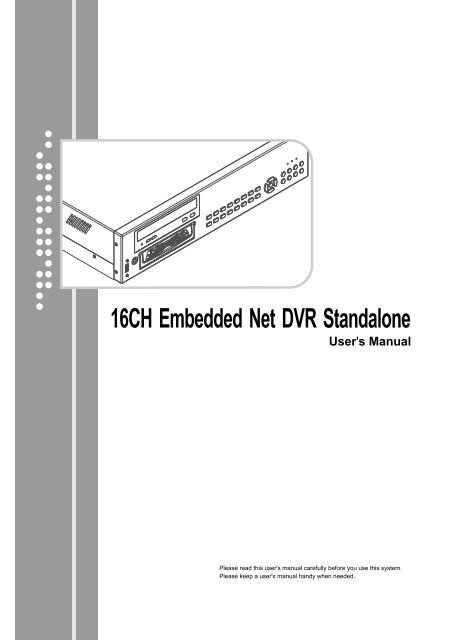
16CH Embedded Net DVR Standalone - Footprint Security
16CH Embedded Net DVR Standalone - Footprint Security
16CH Embedded Net DVR Standalone - Footprint Security

You also want an ePaper? Increase the reach of your titles
YUMPU automatically turns print PDFs into web optimized ePapers that Google loves.
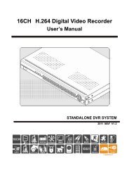
<strong>16CH</strong> <strong>Embedded</strong> <strong>Net</strong> <strong>DVR</strong> <strong>Standalone</strong><br />
User's Manual<br />
Please read this user's manual carefully before you use this system.<br />
Please keep a user's manual handy when needed.
SAFETY PRECATIONS<br />
WARNING<br />
Install this equipment avoiding a direct ray of light, heats and moistures.<br />
Do not pull electric wire or do not touch power plug with wet hands.<br />
Do not bend the power cable forcedly or do not press it with heavy materials.<br />
Do not bend the power cord or loose outlet plug.<br />
Do not use the outlet fully.<br />
Do not disassemble, repair or convert this product without permission.<br />
Do not open the cover of the product at your convenience or do not insert<br />
!<br />
CAUTION<br />
Do not place equipment on the inclined or uneven plane.<br />
Do not vibrate or shock in operation.<br />
Note:<br />
This equipment has been tested and found to comply with the limits for a Class B digital device, pursuant to<br />
Part 15 of the FCC Rules. These limits are designed to provide reasonable protection. This equipment<br />
generates, uses and can radiated radio frequency energy and, if not installed and used in accordance with the<br />
instructions, may cause harmful interference to radio communications. However, there is no guarantee that<br />
interference will not occur in a particular installation If this equipment does cause harmful interference to<br />
radio or television reception, which can be determined by turning the equipment off and on, the user is<br />
encouraged to try to correct the interference by one or more of the following measures:<br />
-Reorient or relocate the receiving antenna.<br />
-Increase these paration between the equipment and receiver.<br />
-Connect the equipment into an outlet on a circuit different from that to which the receiver is connected.<br />
-Consult the dealer or an experienced radio/TV technician of help.<br />
The changes or modifications not expressly approved by the party responsible for compliance could void the<br />
user’s authority to operate the equipment.<br />
Declaration:<br />
All the specification mentioned in this user’s manual is based on the products<br />
when this user’s manual is published. Manufacturer owns the right to alter or<br />
change this product with or without notification. All the products specification<br />
will base on the product itself.<br />
<strong>16CH</strong> <strong>Embedded</strong> <strong>Net</strong> <strong>DVR</strong> <strong>Standalone</strong><br />
01
CAUTION<br />
! The lightning flash with arrowhead symbol, within an equikateral<br />
triangle, is intended to alert the user to the presence of uninsulated<br />
“dangerous voltage” within the product’s enclosure that may be of<br />
sufficient magnitude to constitute a risk of electric shock to persons.<br />
WARNING<br />
This exclamation point witin an equilateral triangle is intended to<br />
alert the user to the presence of important operating and<br />
maintenance (servicing) instructions in the literature accompanying<br />
the appilance.<br />
➣Install this equipment avoiding a direct ray of light, heats and<br />
moistures where may result in lowering efficiency, electric<br />
shock or fire.<br />
➣Do not pull electric wire or don’t touch power plug with wet hands<br />
Can result in electric shock for fire.<br />
➣Do not disassemble, repair or convert this product without permission.<br />
Can result in electric shock or fire. When repair is required,<br />
contact the service center or local distributor.<br />
➣Operation Temperature/Humidity 0~40℃/ under 90% RH;<br />
Power input AC115V/230V<br />
➣Do not expose this equipment to rain or moisture to prevent<br />
electric shock and risk fire hazards<br />
➣Do not use Power source other than that specified (IEC6065/CNS1319)<br />
➣Key away the flammable material or fire to avoid any hazard.<br />
➣Install the product on a well-ventilated place; retain the enough<br />
distance from the rear panel to the wall.<br />
➣Power disconnect: Units with or without ON-OFF switches have<br />
power supplied to the unit whenever the power cord is inserted<br />
into the main source; However, the unit is operational only when<br />
the ON-OFF switch is in the ON position. To disconnect it from the<br />
main source, you have to disconnect the power cord.<br />
➣In case of touching PCB Board, please use proper ESD protection<br />
equipment.<br />
<strong>16CH</strong> <strong>Embedded</strong> <strong>Net</strong> <strong>DVR</strong> <strong>Standalone</strong><br />
02
Chapter 1 : System Specification<br />
1.1 System Hardware Specification<br />
1.2 System Function Specification<br />
1.3 Package Content<br />
Chapter 2 : System Introduction<br />
2.1 System Front Panel<br />
USB<br />
DVD-RW for File Backup<br />
HDD Caddy<br />
Number 1~16 Buttons<br />
Button<br />
Button<br />
Power Indicator ( )<br />
Recording Indicator ( )<br />
Playback Indicator ( )<br />
Record / Switch to Recording Display Button<br />
Setting / List Button<br />
Leftward Button / Playback Backward<br />
Upward button / Step Playback / Pause Playback<br />
Rightward Button / Playback Forward / Output Control<br />
Select / Backup Button<br />
Playback Button<br />
Subtract 1 / Next / Slow Speed Playback<br />
Downward Button / PIP Function<br />
Add 1 / Last One / Fast Speed Forward<br />
Cancel / Stop / Alarm Log Button<br />
6<br />
6<br />
6<br />
7<br />
8<br />
8<br />
8<br />
8<br />
8<br />
8<br />
8<br />
8<br />
9<br />
9<br />
9<br />
9<br />
9<br />
9<br />
9<br />
10<br />
10<br />
10<br />
10<br />
10<br />
11<br />
11<br />
<strong>16CH</strong> <strong>Embedded</strong> <strong>Net</strong> <strong>DVR</strong> <strong>Standalone</strong><br />
03
2.2 System Back Panel<br />
Power Supply<br />
Power Switch<br />
VGA Output<br />
Input Terminals<br />
Output Terminals<br />
Video Input BNC-jacks<br />
TV Monitor Output BNC-jack<br />
Audio Input RCA-jack<br />
Audio Output RCA-jack<br />
Ethernet RJ45-jack<br />
USB<br />
2.3 Hard Disk Installation<br />
Chapter 3 : System Setting<br />
3.1 Setup Main Menu<br />
3.2 Time / Display Setup<br />
3.3 Camera Setup<br />
3.4 Alarm Setup<br />
3.5 System Setup<br />
3.6 <strong>Net</strong>work Setup<br />
Server Setup<br />
Connection<br />
WAN Mode<br />
DIAL-UP Mode<br />
DNS Setup<br />
DDNS Setup<br />
User<br />
<strong>Net</strong>work Info<br />
3.7 Input / Output Setup:(Optional)<br />
Output<br />
S.M.A.R.T.<br />
Input<br />
11<br />
11<br />
11<br />
11<br />
11<br />
11<br />
12<br />
12<br />
12<br />
12<br />
12<br />
12<br />
12<br />
13<br />
13<br />
13<br />
14<br />
15<br />
16<br />
17<br />
18<br />
18<br />
19<br />
20<br />
20<br />
20<br />
21<br />
22<br />
22<br />
23<br />
23<br />
23<br />
<strong>16CH</strong> <strong>Embedded</strong> <strong>Net</strong> <strong>DVR</strong> <strong>Standalone</strong><br />
04
3.8 Program<br />
3.9 Advanced Setup<br />
Chapter 4 : Record<br />
4.1 Activate Record Manually<br />
4.2 Auto Record<br />
4.3 Stop Record<br />
Chapter 5 : Playback<br />
5.1 Assign Time for Playback<br />
5.2 Date List for Playback<br />
5.3 Playback Operation Buttons<br />
Chapter 6 : PIP Function<br />
PIP Sub-Window Location Adjustment<br />
Chapter 7 : Alarm Log<br />
Chapter 8 : I/O<br />
Input Control Setup<br />
Output Control Setup<br />
Output Control<br />
Chapter 9 : File Backup<br />
Chapter 10 : <strong>Net</strong>work Function<br />
10.1 <strong>Net</strong>work Setup<br />
10.2 <strong>Net</strong>work Connection Setup<br />
10.3 Remote File Search<br />
10.4 Remote monitoring by using IE browser<br />
Chapter 11 : <strong>DVR</strong> Player<br />
11.1 Playback Control Panel<br />
11.2 Search<br />
11.3 Color Configuration<br />
11.4 Motion Search Setup<br />
11.5 Continuous Playback<br />
11.6 Caption Display Setup<br />
11.7 VG to AVI Conversion:<br />
24<br />
24<br />
26<br />
27<br />
27<br />
27<br />
27<br />
28<br />
28<br />
29<br />
29<br />
30<br />
30<br />
31<br />
32<br />
32<br />
32<br />
33<br />
34<br />
34<br />
35<br />
39<br />
40<br />
47<br />
48<br />
50<br />
50<br />
50<br />
51<br />
51<br />
51<br />
<strong>16CH</strong> <strong>Embedded</strong> <strong>Net</strong> <strong>DVR</strong> <strong>Standalone</strong><br />
05
Chapter 1 : System Specification<br />
TA-264 is a new generation embedded <strong>DVR</strong> system. This system is using the most<br />
advanced H.264 compression technique. This technique not only holds the best<br />
recording quality and high compression rate. Under the same hard disk sizes, it<br />
can save longer video images and audio sounds.<br />
TA-264 embedded System uses the super high speed DSP IC (Digital signal<br />
Processor) for its center of compression. It records by using hardware images<br />
compression, of this, it can reach a maximum 30 fps (NTSC) or 25 fps (PAL)<br />
recording speed per channel. Playback of the recording is using the same technique<br />
to reach its most efficiency.<br />
1.1 System Hardware Specification :<br />
1. Video In (BNC Jacks): TA-264 : 16 BNC Video In Jacks,<br />
2. Audio In (RCA Jacks): TA-264 : 16 RCA Audio in Jacks<br />
3. Monitor Output : 1 BNC Jack<br />
4. Audio Out : 1 RCA output Jack<br />
5. VGA Output : Supports standard VGA D-SUB outputjack. Resolution<br />
1024 x 768 at 75Hz.<br />
6. Alarm Input : 4 input terminals, Detectable loop circuit open / short.<br />
7. Relay Output : 4 Output control terminal, AC 125V / 12A ; 250V / 7A ; DC 30V / 7A<br />
8. Hard Disk : Support 1 IDE Hard disk<br />
9. Backup Function : Supports 2 USB, to connect to USB disks.<br />
10. Ethernet : RJ45 ( 100/10 Mbps Ethernet)<br />
11. Power : AC115V / 60Hz / 4A, 230V / 50Hz / 2A (Typical)<br />
12. Weight : 7.3 Kg / 9.3 Kg (<strong>Net</strong> / Gross Weight)<br />
13. Size : 380mm x 430mm x 104mm (Length x Width x Depth)<br />
1.2 System Function Specification :<br />
1. Technology : H.264 Hardware real time compression / decompression<br />
2. Resolution : 704 x 480 (NTSC) / 704 x 576 (PAL)<br />
3. Monitoring Speed :<br />
16 channels 480 fps (NTSC) / 400 fps (PAL)<br />
4. Recording Speed :<br />
TA-264 : 240MAX ~ 200MIN fps (NTSC) / 200MAX ~ 167MIN fps (PAL)<br />
5. Image Compression Rate : Dynamic Compression Rate =40:1~240:1(Automatic<br />
Changes depends on the image’s moving situation). Average Dynamic<br />
Compression Rate :40 : 1~2400 : 1<br />
6. Recording Quality : 10 Levels Adjustment available<br />
<strong>16CH</strong> <strong>Embedded</strong> <strong>Net</strong> <strong>DVR</strong> <strong>Standalone</strong><br />
06
7. Audio Recording : 24 Kbps ADPCM recording mode. Synchronize with Video<br />
Recording.<br />
8. Live Audio Monitoring : Support Live Audio Monitoring.<br />
9. Monitor Display : Full Screen, 16 split window display, 8 split window display,<br />
auto scan, 4 split window display at 2/4 pages auto scan and 8 split window<br />
display 2 pages auto scan<br />
10. Internet Function : Supports TCP / IP functions. Supports Internet / LAN<br />
remote monitoring.<br />
11. Multi-task Capability : Supports Recording, Playback, Remote Monitoring and<br />
Live Monitoring at the same time.<br />
12. Sensor Input Trigger Alarm<br />
13. Video Lost Trigger Alarm<br />
14. Motion Image Trigger Alarm (maximum of 4 motion detection areas per<br />
channel)<br />
15. Alert Alarm : Sound Alert and relay output<br />
16. Alarm Record Function : The system will start recording with 3-5 seconds<br />
pre-alarm after alarm triggered.<br />
17. Alarm Log : Record the alarm activated time, alarm source, also select the<br />
time from the alarm log directly for playback.<br />
18. Playback (Search) mode : Playback directly by selected time, search by<br />
saved time log, and by alarm log.<br />
19. Playback Speed mode : Fast Speed forward x2, x4, Slow Speed forward<br />
/2, /4, /6, /8. Single frame playback, Paused, Forward Skip Playback,<br />
Reverse Skip Playback.<br />
20. Playback Display : Full Screen display, 4 split windows display.<br />
21. File Backup Function : Supports USB disk for backup, or retrieving files<br />
from appropriative remote software.<br />
22. Playback backup files : Playback using <strong>DVR</strong> Player directly from a<br />
computer.<br />
23. Remote monitoring software : Installed FUHO 430 on a PC for Remote<br />
monitoring or recording.<br />
24. Firmware Update : Firmware update available from our website at<br />
www.fuho.com.tw update / add / alter the software through USB devices.<br />
1.3 Package Content :<br />
0pening up the package to avoid damage to the system.<br />
1. One TA-264 <strong>Embedded</strong> <strong>DVR</strong> System<br />
2. One Power Cable<br />
3. One User’s manual<br />
4. One CD-ROM<br />
When you found any shortage item when opened, please contact immediately with<br />
the agents, sale representatives or customer service department.<br />
<strong>16CH</strong> <strong>Embedded</strong> <strong>Net</strong> <strong>DVR</strong> <strong>Standalone</strong><br />
07
Chapter 2 : System Introduction:<br />
2.1 System Front Panel:<br />
9<br />
8<br />
7<br />
12<br />
13<br />
14<br />
11<br />
19<br />
17<br />
5<br />
15 18 16<br />
20<br />
10<br />
6<br />
1 3 2<br />
4<br />
System’s front panel includes ‘Numbers and Display control Area’, and ‘Control Button<br />
area’. All button arrangements as above. This is mainly used to operate the main<br />
system. The functions are as followed:<br />
USB (1)<br />
Press once for the panel to open. There is USB application for file download or<br />
firmware update.<br />
DVD-RW for File Backup (2)<br />
HDD Caddy to install HDD (3)<br />
Number 1-16 Buttons (4)<br />
When the number button is press under recording / live mode, the number of camera<br />
displayed will be according to the number of button pressed. When under setting mode,<br />
the number button is for setting of number 1-9.<br />
Button (5)<br />
Button is pressed under recording mode, the display images will be a single image,<br />
or 4 split windows or 8 split windows in different pages. Camera numbers depends on<br />
the pages.<br />
Button (6)<br />
Button is for Auto Scan function for a single, 4 split or 2 split windows in different page.<br />
<strong>16CH</strong> <strong>Embedded</strong> <strong>Net</strong> <strong>DVR</strong> <strong>Standalone</strong><br />
08
Power Indicator( )(7)<br />
When power is on, this indicator will show as red.<br />
Recording Indicator ( )(8)<br />
When system is under recording mode, this indicator will be shown as red.<br />
Playback Indicator( )(9)<br />
When system is under playback mode, this indicator will be shown as yellow.<br />
Record/ Switch to Recording Display Button (10)<br />
1.When system not under recording status, press of this button will activate recording<br />
function immediately.<br />
2.When both recording and playback is functioning: Press this button to switching<br />
back to the recording mode.<br />
3.Note: System’s defaulted is activating recording. You will require to setup “Stop<br />
Recording” under system setup to stop recording.<br />
Setting / List Button (11)<br />
1.Under system setting: Enter System setting, Save setting.<br />
2.Under playback Operation: Enter Date list mode for playback<br />
3.When activate PIP sub-window: Entering the adjustment of PIP sub-window<br />
location, Save PIP sub-window location.<br />
Leftward Button / Playback Backward (12)<br />
1.Under normal operation: Move selection leftward, Go to last page.<br />
2.Under playback operation: For playback backward. Each backward 160 frames<br />
3.When adjusting PIP sub-window: Move the PIP sub-window to the left.<br />
Upward button / Step Playback / Pause Playback (13)<br />
1.Under normal operation: Move selection upward<br />
2.Under playback operation: For step by step playback. Playback of 1 frame then<br />
pause playback.<br />
3.When adjusting PIP sub-window: Move the PIP sub-window to the up.<br />
<strong>16CH</strong> <strong>Embedded</strong> <strong>Net</strong> <strong>DVR</strong> <strong>Standalone</strong><br />
09
Rightward Button / Playback Forward / Output Control: (14)<br />
1.Under normal operation: Move selection rightward, Go to next page.<br />
2. Under playback operation: For playback forward. Each forward 160 frames<br />
3. When adjusting PIP sub-window: Move the PIP sub-window to the right.<br />
4. Not under playback or setting mode: Active output control button. This will display<br />
relay output status, also can stop playing alarm sound.<br />
Detail information will be described later on.<br />
Select / Backup Button (15)<br />
1.Under normal operation: This is for selection and confirm button to select and<br />
confirm the correct setting.<br />
2.Not under playback or setting mode: To activate backup file button. Backup the files<br />
from system hard disk to USB disk/device, by using the playback software <strong>DVR</strong><br />
Player for playback of the file from normal PC. Detail information will be described<br />
later on.<br />
Playback Button (16)<br />
1.Under normal operation: To activate playback function. Selection of the playback<br />
files for playback. Detail information will be described later on.<br />
2.When both recording and playback is functioning:<br />
Switching back to the playback images. Detail information will be described later on.<br />
Subtract 1 / Next / Slow Speed Playback (17)<br />
1.Under normal operation: Subtract 1 when setting numbers or next one selection<br />
button.<br />
2.Under playback mode: Playback speed will be changes each time you press the<br />
button to 1/2 1/4 1/6 1/8 slow speed playback<br />
Downward Button / PIP Function (18)<br />
1.Under normal operation: Move selection downward<br />
2.When both recording and playback is functioning: to activate PIP functions; To<br />
display both recording and playback images we call it PIP function.<br />
PIP sub-window’s location can be altered.<br />
Detail information will be described later on.<br />
Note: PIP function can only be done when connecting VGA output to VGA<br />
monitor. TV output to TV Monitor will not display this function.<br />
<strong>16CH</strong> <strong>Embedded</strong> <strong>Net</strong> <strong>DVR</strong> <strong>Standalone</strong><br />
10
Add 1 / Last One / Fast Speed Forward (19)<br />
1.Under normal operation: Add 1 when setting numbers or last one selection button<br />
2.Under playback mode: Playback speed will be changes each time you press the<br />
button to x2<br />
→<br />
x4 fast speed playback<br />
Cancel / Stop / Alarm Log Button (20)<br />
1.Under normal operation: To cancel setting<br />
2.Under playback mode: To stop image playback.<br />
3.Not under playback or setting mode: To view alarm log. Detail information will be<br />
described later on.<br />
Note: This button is not the stop recording button. Press of this button cannot stop<br />
recording. You will have to select the stop recording function from system setting.<br />
2.2 System Back Panel:<br />
6<br />
7<br />
3 2<br />
10<br />
8 9 4 5 1<br />
System’s back panel is mainly for signal connection. Detail information as followed:<br />
Power Supply<br />
Mark 1: This is for the power supply input socket. AC 110V/60Hz or 220V/50Hz.<br />
Power Switch<br />
Mark 2: Power on/off. To turn on/off the system power.<br />
VGA Output<br />
Mark 3: VGA Output to connect to VGA monitor.<br />
Input Terminals<br />
Mark 4: Input terminal 1-4, for users to connect to sensor devices. Input signal<br />
from left to right is input 1, input 2, input 3, and input 4 and ground connection.<br />
Output Terminals<br />
Mark 5: Relay Output 1-4, for users to connect for controlling of external device.<br />
Signal from left to right (2 connections for 1 relay output) are output 1, output 2,<br />
output 3 and output 4.<br />
<strong>16CH</strong> <strong>Embedded</strong> <strong>Net</strong> <strong>DVR</strong> <strong>Standalone</strong><br />
11
Video Input BNC-jacks<br />
Mark 6 for Video Input 1-16 (Up to Bottom, left to right. .<br />
TV Monitor Output BNC-jack<br />
Mark 7: TV output BNC-jack to connect to TV monitor.<br />
Audio Input RCA-jack<br />
Mark 8 for 1~16 Audio Inputs (order according to numbers displayed, Up to<br />
Bottom, left to right))<br />
Audio Output RCA-jack<br />
Mark 9: Audio out jack for live audio monitoring, or audio output when playback<br />
saved files with audio.<br />
Ethernet RJ45-jack<br />
Mark 10: This is for RJ45 Internet connection socket. This is for 10Mbps/100Mbps<br />
Ethernet<br />
2.3 Hard Disk Installation:<br />
Please take extra notice that the system does not include a hard disk. So before<br />
you start operating this system, it is suggested you install a hard disk for recording<br />
files. The setting for the first hard disk is Master.<br />
Note1: This system is using Linux EXT3 hard disk format. It is suggested to use<br />
the un-partitioned and un-formatted hard disk, or use the already formatted<br />
to Linux EXT3 format hard disk.<br />
Note2:There is no restriction size for a single hard disk capacity. However, the<br />
maximum partition size will be 250GB.<br />
Note3:After a brand new hard disk is installed, this system will automatically partition<br />
and format this hard disk.<br />
When a hard disk is over 250GB, system will automatically separate it into 2 or more<br />
same partition sizes.<br />
<strong>16CH</strong> <strong>Embedded</strong> <strong>Net</strong> <strong>DVR</strong> <strong>Standalone</strong><br />
12
Chapter 3 : System Setting<br />
This is used to setup the system for operation needs. This system includes functions like,<br />
motion detection, alarm functions, security functions, Internet functions and I/O control<br />
etc. Users can setup the system to suit your needs. Detail information as below:<br />
3.1 Setup Main Menu<br />
SETUP 16103 070718 V.1621<br />
1.TIME/DISPLAY<br />
2.CAMERA<br />
3.ALARM<br />
4.SYSTEM<br />
5.NETWORK<br />
6.I/O<br />
7.PROGRAM<br />
8.ADVANCE…<br />
The first line shown on the main menu: First set of number means the firmware version of<br />
this system. Second set of numbers mean the last update date of this firmware.<br />
Ex...”XXXXX 070718” means this system is last updated on 18th July 2007.<br />
3.2 Time / Display Setup<br />
TIME/DISPLAY SETUP<br />
1.DATE 2007-08-28<br />
2.TIME 18:18:08<br />
3.TIME ZONE GMT+08<br />
4.SYSTEM TIME ON<br />
5.CAMERA NAME ON<br />
6.SYSTEM STATUS ON<br />
7.MAIN+SUB DISPLAY OFF<br />
Time / Display setup is for setting the system time and display status. User the up and<br />
down button to select and press the select button to confirm setting:<br />
Date: Use the leftward and rightward button to select year, month and date.<br />
You can also use the number 1-9 and<br />
(as 0) to key in the number directly, (the<br />
numbers will automatically move to the left side), or you can use add 、<br />
subtract button for setup.<br />
Time: Setup hour, minutes and seconds. Setting is as above.<br />
<strong>16CH</strong> <strong>Embedded</strong> <strong>Net</strong> <strong>DVR</strong> <strong>Standalone</strong><br />
13
Time Zone: Use add、 subtract button for setup. For example Taiwan’s time<br />
zone is GMT+08<br />
System Time: The defaulted is on (activate), system will display the system time on<br />
the monitor.<br />
Camera Name: Defaulted is on (activate), system will display the camera name on<br />
the monitor. Camera name will need to setup under “Camera Setup menu”.<br />
System Status: Defaulted is on (activate), system will display system status on the<br />
monitor. Mainly is showing the hard disk sizes and hard disk free spaces.<br />
Note: You must stop recording when setting up date, time and time zone.<br />
MAIN+SUB DISPLAY:Defaulted is “OFF”. Select a camera after changing to “On”,<br />
or when enlarge one of the camera, this camera will not be enlarge as full screen,<br />
instead it will be shown as main screen and other camera images will be shown<br />
around the main screen in smaller screen.<br />
3.3 Camera Setup<br />
CAMERA SETUP : CAMERA1<br />
1.CAMERA NAME CH1--------<br />
2.ENABLE<br />
ON<br />
3.AUDIO<br />
ON<br />
4.DISPLAY<br />
ON<br />
5.BRIGHTNESS 115<br />
6.CONTRAST 130<br />
7.SATURATION 150<br />
8.HUE 128<br />
9.VIDEO CONFIG DEFAULT<br />
Camera setup is to setup the information for each camera. Every camera can be set alone<br />
with depending on the requirement. The above is an example setting for camera 1. Other<br />
cameras can be setup using the same way. Users can use leftward, rightward<br />
buttons to changes to different camera setup menu.<br />
Note: When setting up the camera, the images correspondence to the camera will be<br />
displayed as full sizes for adjusting brightness, contrast, saturation and hue. Press<br />
to save the setting.<br />
Camera Name: You can only setup the camera name using English or alphabet.<br />
You can use the number button directly for setting or use add or substrate for setting.<br />
Enable: Defaulted is on (activate), if the camera does not connect to a camera, user<br />
can disable (OFF) this selection, and then this will not be record.<br />
<strong>16CH</strong> <strong>Embedded</strong> <strong>Net</strong> <strong>DVR</strong> <strong>Standalone</strong><br />
14
Audio: Defaulted is on (activate). Audio functions uses 24kbps ADPCM format for<br />
recording. File sizes are approximate 10MB per channel per hour.<br />
Display: Defaulted is on (activate), you can change to off if display not require.<br />
Brightness: Brightness adjustment. Defaulted is 115, adjusting range from 0-255, 0<br />
is the darkest and 255 is the brightness.<br />
Contrast: Contrast adjustment. Defaulted is 130, setting range from 0-225, 0 is the<br />
lowest and 255 is the highest.<br />
Saturation: saturation adjustment. Defaulted is 150, setting range from 0-225, 0 is<br />
the lowest and 255 is the highest.<br />
Hue: Hue adjustment. Defaulted is 128, setting range from 0-255.<br />
Video Configuration Default: When users want to get back to the defaulted brightness,<br />
contrast, saturation and hue, press the select / confirm button and press<br />
to save the setting.<br />
3.4 Alarm Setup<br />
This system supports alarm functions, which include sensor input trigger alarm, video lost<br />
trigger alarm, and motion image trigger alarm. Alarm setup is to setup the alarm function<br />
for each camera. Every camera has its own setting. Below is the setup menu for the<br />
camera 1, other cameras can be setup using the same method. Users can use<br />
leftward、 rightward to change to different camera setup menu.<br />
ALARM SETUP : CAMERA1<br />
1.VIDEO LOST CHECK ON<br />
2.MOTION DETECT 9<br />
3.ALARM SOUND OFF<br />
4.ALARM INTERVAL 120<br />
5.MASK1 00 00:00 00<br />
6.MASK2 00 00:00 00<br />
7.MASK3 00 00:00 00<br />
8.MASK4 00 00:00 00<br />
9.OUTPUT TRIGGER – -- -- –<br />
Video Lost Check: Checking video lost. Defaulted is on (activate) so when video<br />
lost, system will trigger alarm.<br />
Motion Detect: Enable or disable motion detection and setup the detection<br />
sensitivity. Defaulted sensitivity is 9, its range is from 1-16 or off to disable the<br />
motion detection. 1 is the less sensitivity and 16 is the most sensitivity.<br />
Alarm Sound: This is to setup the alarm sound when alarm triggered. Defaulted is<br />
<strong>16CH</strong> <strong>Embedded</strong> <strong>Net</strong> <strong>DVR</strong> <strong>Standalone</strong><br />
15
off (disable), system’s built-in 4 different alarm sound, you can use add, subtract or the<br />
number1-4 to setup different alarm sound or off to disable alarm sound.<br />
Alarm Interval: This is used to setup the alarm interval, defaulted is 120seconds, setting<br />
range from 100-999seconds.<br />
Mask 1-4: You can setup maximum of 4 detection areas for each camera. Each images is<br />
seen as 22 x 15 (NTSC) or 22 x 18 (PAL), so you can set a maximum of 4 area in (00 00)<br />
~(22 15) (NTSC) or(00 00)~(22 18) (PAL).(00 00) is the top left hand side and NTSC<br />
(22 15) / PAL(22 18) is the right bottom side. When there is motion in the masked area,<br />
it will trigger alarm. When alarm triggered, it will be save in the alarm log. User can<br />
playback the alarm files from the alarm log.<br />
Output Trigger: When alarm triggered, it can be set to control the external alarm device<br />
form the output terminals. There are a total of 4 relay output control terminals for selection.<br />
This output control terminals is optional.<br />
3.5 System Setup<br />
SYSTEM SETUP<br />
1.VIDEO MODE NTSC<br />
2.RECORD SPEED 30<br />
3.VIDEO QUALITY 10<br />
4.SCAN TYPE QUAD DISPLAY<br />
5.SCAN INTERVAL 3<br />
6.AUTO RECORD ON<br />
7.LIVE AUDIO ON<br />
8.ALARM RECORD OFF<br />
9.VGA-PIP OFF<br />
Video Mode: Video modes include the selection of NTSC and PAL. Users must change<br />
it according to your local video mode. You will need to stop recording before changing<br />
the setting.<br />
Record Speed: Maximum recording speed per channel is 30fps NTSC or 25fps PAL.<br />
Video Quality: Video quality range is from 1-10. Quality 10 means the best quality<br />
however the largest the recorded file sizes. User’s can change the video quality to<br />
your needs. However, low quality also will influence the playback quality.<br />
<strong>16CH</strong> <strong>Embedded</strong> <strong>Net</strong> <strong>DVR</strong> <strong>Standalone</strong><br />
16
Scan Type: This is to setup the auto scan type. FULL DISPLAY (single camera full<br />
screen display, recycling for every channels), or QUAD DISPLAY (4 split window /2<br />
pages display,), or Eighth Display (as 9 split windows and 4 pages display)<br />
Scan Interval: This is to setup up the interval for auto scan. Defaulted is 3 seconds.<br />
Maximum interval time is 99 seconds.<br />
Auto Record: When auto record is set at ON (activate), when system reboot, system<br />
will automatically start recording. If this setting is OFF (disable), then user will need to<br />
press the record button manually for the system to start recording.<br />
Live Audio: When this is activated, and you had connected audio input to the<br />
correspondence cameras, you are able to have live audio monitoring when the sound<br />
is connect to a speaker.<br />
ALARM RECORD: When system not under recording mode, after activated of this<br />
function, the system will start recording after alarm triggered. Recording time is the<br />
time set between alarm intervals with 3-5seconds pre-alarm. Also input points can<br />
activate alarm records. Recording time is the signal input time.<br />
VGA-PIP: PIP (Picture in Picture) functions us use to see both record and playback<br />
images at once. When it is set at on (activate), press the bottom, there will be a<br />
sub-window showing on the VGA monitor. Then both recording and playback<br />
images can be see at the same time. Press the bottom again then the<br />
sub-window will be disappeared.<br />
Note: PIP function can only support by VGA output connects to VGA monitor. TV<br />
monitor does not support this function.<br />
3.6 <strong>Net</strong>work Setup<br />
NETWORK SETUP : SERVER SETUP<br />
1.HOST NAME<br />
SRT.16-----<br />
2.CONNECT SERVER ON<br />
3.SERVER 192.168.16.127<br />
--------------------<br />
4.SERVER PORT 40000<br />
5.DISCONNECT ALM – – – –<br />
<strong>Net</strong>work Setup is to setup the network connection function. You can setup the system’s<br />
network connection and also you can setup 4 sets for remote user’s name, password,<br />
authorization and camera.<br />
<strong>16CH</strong> <strong>Embedded</strong> <strong>Net</strong> <strong>DVR</strong> <strong>Standalone</strong><br />
17
You will require setting the “Connect Server” to off before setup/alter <strong>Net</strong>work Setup and<br />
Remote User.<br />
Server Setup:<br />
When enter this setup, the above server setup pages will be shown.<br />
Host Name: Host name is used for recognition when connecting in the Internet.<br />
Defaulted host name is SRT4.16. Users can change the name easier to recognize.<br />
You will require setting the “Connect Server” to “off” before setup/alter the host name.<br />
Connect Server: System will connect to the server according to the setting when it is<br />
set as on. If set at off, then system will not connect to server.<br />
Server: For <strong>Net</strong>work connection, system will need to connect to the PC running the<br />
Server program. Server address is the IP address for that PC. Server IP address can<br />
also be a domain name. For Example, the PC running the server program does not<br />
have a fix IP address; you can apply a Dynamic Domain Name from the supplier to<br />
connect the hosts on the network. Domain name will require DNS setup.<br />
Server Port: It is suggest setting the communication port for the Server program as<br />
defaulted 40000 when setting the remote connection. Please do not change it if not<br />
necessary. If alteration is a must, then you will require changing all three<br />
communication ports to the same value for <strong>Embedded</strong> <strong>DVR</strong>, Server (FUHO Server)<br />
Program and Remote server for FUH0 430<br />
Disconnect Alarm (Output): When connect server is set as on, if system is not able<br />
to make connection to server, an alarm output notice will be made. User will be able<br />
to use this output signal to control external alarm equipment. There are 4 sets of<br />
relay output for selection. (Relay equipment are optional)<br />
Connection<br />
User can use left, right to enter connection setup<br />
NETWORK SETUP : CONNECTION<br />
1.LISTEN PORT 50000 50000<br />
2.MODE<br />
LAN<br />
3.GET IP<br />
AUTO GET IP<br />
Listen Port: LAN users use the first value; WAN users use the second value.<br />
Defaulted value is 50000. Internet connection will require changing the<br />
communication ports. Please refer to Chapter 10 <strong>Net</strong>work Connection Setup.<br />
Mode: There are three connection modes. LAN mode, WAN mode and Dail-Up mode<br />
using (PPPoE).<br />
<strong>16CH</strong> <strong>Embedded</strong> <strong>Net</strong> <strong>DVR</strong> <strong>Standalone</strong><br />
18
Get IP: Under LAN mode, IP setup can be Auto get IP and manually set IP. If the LAN<br />
network is with DHCP function, the IP address can be automatically got.<br />
NETWORK SETUP : CONNECTION<br />
1.LISTEN PORT 50000 50000<br />
2.MODE<br />
LAN<br />
3.GET IP<br />
MANUAL SETUP IP<br />
4.LOCAL IP 000.000.000.000<br />
5.NET MASK 000.000.000.000<br />
6.GATEWAY 000.000.000.000<br />
Manual Get IP<br />
Under LAN Mode, users can manually setup IP.<br />
Local IP, <strong>Net</strong> Mask, Gateway: The IP address for Local IP, <strong>Net</strong> Mask and Gateway for the<br />
System.<br />
NETWORK SETUP : CONNECTION<br />
1.LISTEN PORT 50000 50000<br />
2.MODE<br />
WAN<br />
3.LOCAL IP 000.000.000.000<br />
4.NET MASK 000.000.000.000<br />
5.GATEWAY 000.000.000.000<br />
WAN Mode<br />
User with Fix IP address can select WAN Mode.<br />
Local IP, <strong>Net</strong> Mask, Gateway: Under WAN Mode, Local IP, <strong>Net</strong> mask and Gateway setting<br />
is the information provided from your ISP.<br />
NETWORK SETUP : CONNECTION<br />
1.LISTEN PORT 50000 50000<br />
2.MODE<br />
DIAL-UP<br />
3.USERNAME MANUAL SETUP IP<br />
4.PASSWORD 000.000.000.000<br />
5.AUTO CONNECT ON<br />
<strong>16CH</strong> <strong>Embedded</strong> <strong>Net</strong> <strong>DVR</strong> <strong>Standalone</strong><br />
19
DIAL-UP Mode<br />
Users with PPPoE connection can select Dial-Up Mode.<br />
User Name, Password: Username and password is require to enter when connection.<br />
There might not be a small letter available for some systems, User will require putting<br />
“+” in front of every letter if the password and username is small letter. For example,<br />
user’s name is “chateau”, you will require to enter as +C+H+A+T+E+A+U. Using<br />
、 button to enter the word.<br />
Auto Connect: When activated, system will auto connect when system restarts.<br />
DNS Setup<br />
User can use left, right to enter DNS (Domain Name Server) setup. DNS will<br />
let the domain name correspond to the correct IP address. If the connected server is a<br />
domain name then DNS setup is required.<br />
NETWORK SETUP :<br />
1.GET IP<br />
DNS SETUP<br />
AUTO GET IP<br />
GET IP: There are Auto Get IP and Manual Setup IP for setting of DNS IP address.<br />
Auto Get IP can be done when a DNS address is assigned under LAN.<br />
NETWORK SETUP : DNS SETUP<br />
1.GET IP MANUAL SETUP IP<br />
2.PRIMARY IP 000.000.000.000<br />
3.SECONDARY IP 000.000.000.000<br />
Get IP: DNS IP can be manually setup.<br />
Primary IP, Secondary IP: User can setup 2 sets of DNS IP.<br />
DDNS Setup<br />
TA-264 system support DDNS function, Users can uses left 、 right button to<br />
enter the DDNS (Dynamic Domain Name Server) setup. If the IP for this <strong>Embedded</strong> <strong>DVR</strong><br />
is a real IP in Internet, no matter is a fixed IP or Floating IP, you can apply a Dynamic<br />
Domain Name for this <strong>DVR</strong>. Of which means DDNS will require to be set from<br />
NETWORK SETUP → CONNECTION → MODE : WAN or DIAL-UP. After DDNS is set,<br />
when monitoring through IE browser, then IP address is not necessary, domain name will<br />
be required.<br />
<strong>16CH</strong> <strong>Embedded</strong> <strong>Net</strong> <strong>DVR</strong> <strong>Standalone</strong><br />
20
Firstly, users will require applying for a DDNS account and password and a domain<br />
name. There are 4 DDNS suppliers that is supported at this moment, you can select<br />
any one of the below<br />
● dyndns.org<br />
● no-ip.com<br />
● freedns.afraid.org<br />
● zoneedit.com<br />
NETWORK SETUP : DDNS SETUP<br />
1.ENABLE<br />
OFF<br />
2.DOMAIN NAME ---------------<br />
---------------<br />
---------------<br />
3.USER NAME ---------------<br />
---------------<br />
4.PASSWORD ---------------<br />
---------------<br />
5.DDNS SERVER dyndns@dyndns.org<br />
ENABLE:Activate DDNS function. When setup as “On”, it will enter DDNS<br />
automatically and transfer the IP address in use to DDNS.<br />
DOMAIN NAME:Please enter the domain name you applied from DDNS supplier.<br />
USER NAME:Please enter the user name you register with DDNS supplier.<br />
PASSWORD:Enter the password you register with DDNS supplier.<br />
DDNS SERVER:Select the DDNS supplier you select.<br />
User<br />
User can use left or right buttons to enter the setup pages for remote user 1 /<br />
user 2 / user 3 and user 4 to setup the authorization for remote.<br />
NETWORK SETUP : REMOTE USER1<br />
1.USER NAME AAAA----------<br />
2.PASSWORD AAAA----------<br />
3.SETUP<br />
ON<br />
4.DOWNLOAD ON<br />
5.OUTPUT<br />
OFF<br />
6.CAMERA1-4 ON ON ON ON<br />
7.CAMERA5-8 ON ON ON ON<br />
8.CAMERA9-12 ON ON ON ON<br />
9.CAMERA13-16 ON ON ON ON<br />
<strong>16CH</strong> <strong>Embedded</strong> <strong>Net</strong> <strong>DVR</strong> <strong>Standalone</strong><br />
21
User Name: This is to setup the user’s name who allows connecting to this system.<br />
Password: This is to setup the user’s password which allows connecting to this system<br />
Setup: This is to authorize remote user to enter system setup and Video Configuration<br />
functions.<br />
Download: This is to allow remote user to download/retrieve history database from the<br />
system.<br />
Output: This is to allow user to remote control relay output (optional)<br />
Camera 1-4: This is to display the camera that the remote user is allowed to monitor.<br />
Unauthorized camera will not be displayed. From left to right are camera 1/ camera 2/<br />
camera 3/ camera4.<br />
Camera 5-8: This is to display the camera that the remote user is allowed to monitor.<br />
From left to right are camera 5/ camera 6/ camera 7/ camera8. (8 channels or above<br />
systems support camera 5-8)<br />
Camera 9-12: This is to display the camera that the remote user is allowed to monitor.<br />
From left to right are camera 9/ camera 10/ camera 11/ camera 12. (16 channels<br />
system support camera 9-12)<br />
Camera 13-16: This is to display the camera that the remote user is allowed to monitor.<br />
From left to right are camera 13/ camera 14/ camera 15/ camera 16. (16 channels<br />
system support camera 13-16)<br />
<strong>Net</strong>work Info<br />
User can use left or right buttons to enter the <strong>Net</strong>work Info.<br />
NETWORK SETUP : NETWORK INFO<br />
1.LOCAL IP 000.000.000.000<br />
2.DNS SERVER 000.000.000.000<br />
3.MAC ADDRESS 000.000.000.000<br />
4.DDNS CONNECT FAIL<br />
<strong>Net</strong>work Info will display the IP address for System IP, DNS, MAC (Media Access Control).<br />
And the DDNS connection status.<br />
3.7 Input /Output Setup: (Optional)<br />
IO SETUP : OUTPUT<br />
1.OUTPUT1 ON 20<br />
2.OUTPUT2 OFF 30<br />
3.OUTPUT3 ON ---<br />
4.OUTPUT4 --- ---<br />
5.S.M.A.R.T -- -- -- –<br />
<strong>16CH</strong> <strong>Embedded</strong> <strong>Net</strong> <strong>DVR</strong> <strong>Standalone</strong><br />
22
Input/Output setup is to setup the output status and the input’s signal status. Users<br />
must setup the output status to correctly control the external devices. Input is to detect<br />
the status of the device. When input is triggered, then the system can corresponded<br />
according to the setting.<br />
When enter this setup menu, it will be the setup of output. Users can use leftward,<br />
rightward to enter the input setup menu.<br />
Output<br />
There are 4 output control terminals. Each can be set independently. When output<br />
status setup is “---” means no output. If setting is on, means under normal condition<br />
relay output open, and if activated, then the relay output short. If the setting is off, then<br />
under normal condition, relay output short and if activated, then the relay output open.<br />
S.M.A.R.T.(Smart Monitoring, Analysis, and Reporting Technology)<br />
System will auto detect per 12h, analysis and reporting the status of HDD. When there<br />
is any unusual situation, then an alarm will be outputted. User will be able to use this<br />
output signal to control external alarm equipment. There are 4 sets of relay output for<br />
selection. (Relay equipment is optional)<br />
Input<br />
This system has 4 input terminals. Each input can be set independently. Users can use<br />
below:<br />
leftward,<br />
rightward to enter the different input setup menu. Setup menu as<br />
IO SETUP : INPUT1<br />
1.TRIGGER TYPE ---<br />
2.ALARM SOUND ---<br />
3.OUTPUT1 ---<br />
4.OUTPUT2 ---<br />
5.OUTPUT3 ---<br />
6.OUTPUT4 —<br />
Trigger Type : Input terminals are mainly connection to switching devices. The device<br />
is separate into No (Open under normal condition) and NC (Short under normal<br />
condition). Wrong setting will cause error action. When input potential is “---“, it means<br />
disable. Input potential is “High” will require to use NO (Open under normal condition)<br />
and when input potential is “Low”, the NC (Short under normal condition) will be used.<br />
It is suggest using the device using NC. This means that when it is triggered, or<br />
connection cut off, it will trigger alarm.<br />
Alarm Sound: This is use to setup the alarm sound when input terminals is triggered.<br />
You can use the 4 built-in sounds for setting.<br />
<strong>16CH</strong> <strong>Embedded</strong> <strong>Net</strong> <strong>DVR</strong> <strong>Standalone</strong><br />
23
Output 1-4: This setting is to send out control signal to control external alarm devices<br />
when input terminals had been triggered, each input terminals can setup 1-4 output<br />
control. Output setting “---“means disable, “ON” means active. Please refer to the<br />
output setup instruction above for setting.<br />
3.8 Program<br />
PROGRAM SETUP: PROGRAM 1<br />
1.ENABLE: OFF<br />
2.SUN-SAT OFF OFF OFF OFF<br />
OFF OFF OFF<br />
3.BEGIN TIME: 00:00:00<br />
4.END TIME: 00:00:00<br />
Setting of 4 sets of programs for recording. Each set is based on a week time.<br />
Setting a same recording time for each program. Enable/disable of each date from<br />
Sunday to Saturday can be set independently.<br />
3.9 Advanced Setup<br />
ADVANCED SETUP<br />
1.STOP RECORD<br />
2.LOGOUT<br />
3.LOGOUT AND RECORD<br />
4.PASSWORD ----------<br />
5.UPDATE FIRMWARE<br />
6.LOAD DEFAULT<br />
7.FORMAT DVD(OPT)<br />
8.SCAN HDD<br />
9.FORMAT HDD HDA1 147.4G<br />
Stop Record: This system’s recording status is not able to stop recording from any<br />
button on the front panel. This is for security reason. So you will require entering this<br />
setup menu to stop recording.<br />
Logout: This is for security reason. To avoid any changes of the setting from<br />
unauthorized person, it is suggested to logout after setting password. When logging<br />
in the system then re-enter the password for operating of the system and setting.<br />
<strong>16CH</strong> <strong>Embedded</strong> <strong>Net</strong> <strong>DVR</strong> <strong>Standalone</strong><br />
24
Logout and Record: If the user did not setup “Auto Record” function, when log out,<br />
system will not be operating and will not be able to start recording even if you press<br />
the recording button on the front panel. You can then use this setup to activate<br />
recording when log out.<br />
Password: Users can setup the password yourself to avoid any operating from<br />
unauthorized person. Please log out after you set the password for it to be valid.<br />
Update Firmware: When we provide firmware update, users can download it from our<br />
website. Create a directory name as “firmware” in the USB device and download the<br />
update firmware in this directly in a USB device. Connect the USB device to the USB<br />
sockets of the system, activate this function, the system will then automatically update<br />
the firmware. System will need to reboot (Automatically) to finish firmware update.<br />
Load Default: System will be change back to its default value. This would avoid the<br />
error setting by the users, which might cause abnormal operating of the system.<br />
FORMAT DVD-RW:This support the burner (DVD burner). User can use DVD±R<br />
and DVD±RW to backup Video files. It suggests to format DVD±RW disks on this<br />
<strong>Embedded</strong> <strong>DVR</strong> to make sure this function can work normally. Format will delete all<br />
the data on the disks to burn new data into it.<br />
SCAN HDD:Activate this functions can scan the system files in the HDD, then clear<br />
or fix the error files.<br />
Format HDD: After installing of the hard disk (Suggest not to partition or format the<br />
HDD before installed) system will automatically detect and automatically partition and<br />
format the hard disk. When user wants to format it again, this function can be used.<br />
Note: HDD display HDA1/HDB2. “A” means the master HDD (HDD number1).<br />
B means the slave HDD (HDD number2). The number 1 means the 1st partition<br />
and 2 means the 2nd partition.<br />
<strong>16CH</strong> <strong>Embedded</strong> <strong>Net</strong> <strong>DVR</strong> <strong>Standalone</strong><br />
25
Chapter 4 : Record<br />
When system turns on, system will need about 1 minute to boot and then to display images.<br />
When system is turned on but without installed with HDD or connected to camera, the<br />
below left hand side split window will be displayed:<br />
Image Section: Camera arrangement is from top to bottom, left to right as camera<br />
1-8, a total of 8 image section .<br />
Status Section: Bottom right hand side is the status section, it display the system<br />
time and hard disk status. The above left hand side picture is displayed when hard<br />
disk is not installed. When hard disk is installed then it will display the partition, free<br />
spaces and total capacity messages as above right hand side pictures.<br />
Note: Hard disk space is calculated as hexadecimal, so 1024 means K, not decimal<br />
system. Please be aware the differences.<br />
Each camera images is displayed according to the setting. Detail information as below:<br />
Image: Without camera signal input, the image will be displayed as “VIDEO LOST”.<br />
With video input, then image will be displayed.<br />
Camera Name: The camera name will be shown on the top left hand side of the<br />
image for every camera.<br />
Active:If symbol is displayed on the image, this means that this camera is<br />
selected (Active). If this camera is with audio recording, you will be able to hear the<br />
sound when this camera selected.<br />
Record: When<br />
recording status.<br />
symbol is displayed, this means that this camera is under<br />
Audio: If symbol is displayed, this means that this camera is under audio<br />
recording status.<br />
Alarm: If symbol is displayed, this means that this camera alarm had been<br />
triggered. When alarm triggered, system will automatically save it to alarm log for<br />
users to check.<br />
<strong>16CH</strong> <strong>Embedded</strong> <strong>Net</strong> <strong>DVR</strong> <strong>Standalone</strong><br />
26
4.1 Activate Record Manually<br />
System will start operating according to the setting. If the auto record is set as off under<br />
system setting, system will not automatically start recording. This record button will<br />
need to be pressed to activate recording. You will be able to see the symbol or<br />
whether the recording indicator from the front panel.<br />
4.2 Auto Record<br />
If the Auto record is set as ON under system setting, system will automatically start<br />
recording when turned on.<br />
4.3 Stop Record<br />
This system will not be able to stop recording from any button on the front panel. You<br />
will require entering the “advanced setup” and selecting the “stop record” to stop recording.<br />
Chapter 5 : Playback<br />
This system is with multi task capability. You can also playback images when recording.<br />
But a maximum of 4 images can be played back at once. (channel 1-4 ,channel 5-8,<br />
channel 9~12 or channel 13~16). Playback image as below:<br />
Camera Name: On playback images, camera name will be shown on the top left<br />
hand side of the image for every camera.<br />
Active:If symbol is displayed on the image, this means that this camera is<br />
selected (Active). If this camera is with audio recording, you will be able to hear the<br />
sound when this camera selected.<br />
Playback: When<br />
playback image.<br />
is displayed on the images, this means that this images is<br />
Time display: On playback images, recording time and date will be display on the<br />
right bottom side of the images for every camera.<br />
Pause: When<br />
is displayed, it means that the playback image is under paused.<br />
<strong>16CH</strong> <strong>Embedded</strong> <strong>Net</strong> <strong>DVR</strong> <strong>Standalone</strong><br />
27
5.1 Assign Time for Playback<br />
Press playback button, then the following menu will be shown:<br />
PLAYBACK<br />
1.START DATE 2007-07-05<br />
2.START TIME 13 : 00 : 00<br />
3.CAMERA 1 – 4<br />
Use up, down, left right, add, subtract, select buttons to changes the numbers.<br />
You can change the playback file start date, start time or camera number. After setting,<br />
press the playback button again to start playback.<br />
5.2 Date List for Playback:<br />
Users can also press button and then press list button to playback files from the<br />
date and time lists.<br />
PLAYBACK DATE LIST<br />
DATE HDD<br />
2007-07-05 HDA1<br />
2007-07-04 HDA1<br />
2007-07-03 HDA1<br />
2007-07-02 HDA1<br />
After select the playback date file, the following will be shown:<br />
FILE LIST : 2007-05-05<br />
START END CAMERA SIZE<br />
13: 00: 07 14: 00: 09 5-8 565.0M<br />
13: 00: 07 14: 00: 09 1-4 718.0M<br />
12: 00: 05 13: 00: 07 5-8 636.1M<br />
12: 00: 05 13: 00: 07 5-8 590.2M<br />
11: 00: 06 12: 00: 07 5-8 379.9M<br />
11: 00: 06 12: 00: 05 1-4 412.9M<br />
10: 00: 03 11: 00: 06 5-8 172.0M<br />
10: 00: 03 11: 00: 06 5-8 191.2M<br />
Use the up and down button to select the playback time and camera number. Press<br />
select or playback buttons to playback files.<br />
<strong>16CH</strong> <strong>Embedded</strong> <strong>Net</strong> <strong>DVR</strong> <strong>Standalone</strong><br />
28
5.3 Playback Operation Buttons<br />
Playback backward: Press the<br />
time this button is pressed.<br />
Playback forward: Press<br />
this button is pressed.<br />
button to playback 160frames backward each<br />
button to playback 160frames forward each time<br />
Playback Slow Speed: Playback speed will be changes each time you press the<br />
button to 1/2 →1/4 →1/6 →1/8 slow speed playback<br />
Playback Fast Speed: Playback speed will be changes each time you press the<br />
button to x2 → x4 fast speed playback.<br />
Step Playback / Pause: Each time this<br />
played back and then paused.<br />
is pressed, a single frame will be<br />
Stop Playback: Press button to stop all playback images. Playback images will<br />
be disappeared and change back to recording images.<br />
If the record files recorded from alarm records. Because the alarm time is not<br />
continually, the system will automatically paused and playback next alarm file only<br />
when user press the playback button.<br />
Chapter 6 : PIP Function<br />
PIP functions only support VGA monitor output. This system does not support TV monitor<br />
output for PIP function. If user only connects to TV monitoring output, please do not activate<br />
this VGA-PIP function.<br />
When system is recording and playing back files at the same time, users can use the<br />
record and playback button to switch between record or playback images. If user requires<br />
to display both record and playback images together, then you can use the PIP function<br />
to display. Before using the VGA-PIP functions, please activate the “VGA-PIP setting” from<br />
the “system setup” to ON.<br />
Press the PIP button under recording, Main window is the recording images and<br />
Sub-Window is the playback images.<br />
<strong>16CH</strong> <strong>Embedded</strong> <strong>Net</strong> <strong>DVR</strong> <strong>Standalone</strong><br />
29
If under playback, and this button is pressed, then the main window will be playback<br />
images and sub-window will be recording images.<br />
Press this PIP button again to cancel PIP sub-window. User can also use the record and<br />
playback button to switch from main window to sub-window.<br />
PIP Sub-Window Location Adjustment<br />
When PIP Sub-window is displayed, press the setup<br />
right etc buttons to move PIP sub-window location.<br />
button, then use up, down, left<br />
If cancel button is pressed after adjustment, then the new location will not be saved. If<br />
select/confirm button is press after adjustment, then the new location will be saved.<br />
When user activates PIP function next time, PIP will display at the new location saved.<br />
Chapter 7 : Alarm Log<br />
This system is with alarm function. There are three ways to trigger alarm. Motion Image<br />
Trigger Alarm (Move), Sensor Input Trigger Alarm (Input) and Video Lost Trigger Alarm<br />
(Loss). Any alarm triggered wills results an alarm messages in the alarm log. User can<br />
then user this alarm log to check for the alarm situation.<br />
Press Alarm Log button, the following will be displayed:<br />
ALARM LOG DATE LIST<br />
DATE HDD<br />
2007-05-05 HDA1<br />
2007-05-04 HDA1<br />
2007-05-03 HDA1<br />
2007-05-02 HDA1<br />
2007-05-01 HDA1<br />
2007-04-30 HDA1<br />
2007-04-29 HDA1<br />
<strong>16CH</strong> <strong>Embedded</strong> <strong>Net</strong> <strong>DVR</strong> <strong>Standalone</strong><br />
30
Users can check the alarm log according to the date. After selection, press select / confirm<br />
button, the following picture will be shown to check for more detail alarm log:<br />
ALARM LOG : 2007-05-05<br />
13 : 02 : 05 CAMERA5 LOSS END<br />
13 : 00 : 25 CAMERA5 LOSS START<br />
12 : 32 : 35 CAMERA3 MOVE END<br />
12 : 30 : 35 CAMERA3 MOVE START<br />
11 : 02 : 32 INPUT1 END<br />
11 : 02 : 02 INPUT1 START<br />
10 : 35 : 24 CAMERA2 LOSS END<br />
If under the alarm log is recorded because of motion, use the up and down buttons to<br />
select to the record and use select/confirm button to select to playback the images.<br />
Also recycling of the hard disk motion or stop recording motion from advance setting will<br />
also create an alarm log.<br />
Chapter 8 :I/O<br />
Input control is used to detect the situation of the sensor and then the system will react<br />
according to the setting. Output control is the relay output. You can use the relay output<br />
to control external devices, which include external alarm devices or even as usage of<br />
power switch.<br />
Input Control Setup<br />
An input terminal is mainly connected to the switch devices. Switching devices is separate<br />
into NO (Open: OPEN) and NC (Close: Short). Input detection is also separate into High<br />
potential and Low Potential. Inputs itself is high potential, going through the switch device<br />
and connect to ground. If the switch device is open, then the input terminal will detect is<br />
high potential. If switch is short, input terminal will detect low potential.<br />
When input potential is set at high, it means it is high potential under normal condition,<br />
you will require to use NO (Open) device. When sensor triggered, it will become short<br />
circuit, and then the input terminal will detect low potential, then the system will triggered<br />
the alarm.<br />
When input potential is set at low, it means it is low potential under normal condition,<br />
you will require to use NC (Close) device. When sensor triggered, it will become open<br />
circuit, and then the input terminal will detect high potential, then the system will triggered<br />
the alarm.<br />
Input terminal’s triggered potential means enable when set at “---“<br />
<strong>16CH</strong> <strong>Embedded</strong> <strong>Net</strong> <strong>DVR</strong> <strong>Standalone</strong><br />
31
Note: Wrong setting will cause error alarm triggered. It is suggest using the device<br />
sing NC. This means that when it is triggered, or connection cut off, it will trigger<br />
alarm.<br />
Output Control Setup<br />
Output control is mainly controlling the relay output. Relay output itself is only the on/off<br />
device. It is not with any power signal output. So other than connect it to the needed<br />
devices, necessary power will need to connect as well.<br />
If output setting is “ON”, this means under normal condition, relay output is open loop<br />
circuit, after activated; relay output will become close loop circuit.<br />
If output setting is “OFF”, this means under normal condition, relay output is close loop<br />
circuit, after activated; relay output will become open loop circuit.<br />
Output not controllable when output setup is “---“<br />
Output Control<br />
When<br />
output control button is pressed, the following picture will be shown:<br />
MUTE/OUTPUT CONTROL<br />
1.MUTE<br />
2.OUTPUT1 OFF<br />
3.OUTPUT2 OFF<br />
4.OUTPUT3 OFF<br />
5.OUTPUT4 OFF<br />
1.Use this output control to shut off the alarm sound when alarm triggered.<br />
2.Use up, down buttons to select the outputs and press select button to adjust output<br />
from OFF→ON or ON→OFF.<br />
<strong>16CH</strong> <strong>Embedded</strong> <strong>Net</strong> <strong>DVR</strong> <strong>Standalone</strong><br />
32
Chapter 9 : File Backup<br />
By connecting USB devices (USB flash disk , USB Hard disk and USB DVD Burner) to<br />
the system, you will able to backup file. Before you backup the files, please format the<br />
USB flash disk and USB Hard Disk as FAT32, otherwise it might not be able to detect<br />
from the system. It is suggest to format the DVD disks on this <strong>Embedded</strong> <strong>DVR</strong>.<br />
Connect the USB device to the USB sockets at the back of the system, press<br />
USB backup function, the following picture will be shown:<br />
FILE BACKUP DATE LIST<br />
DATE HDD<br />
2007-05-05 HDA1<br />
2007-05-04 HDA1<br />
2007-05-03 HDA1<br />
Use up and down button to select the files date for backup and press the select button<br />
the following will be shown:<br />
FILE LIST : 2007-05-03<br />
START END CAMERA LENGTH<br />
14:00:00 15:00:00 1-4 660.0M<br />
14:00:00 15:00:00 5-8 662.3M<br />
13:00:00 14:00:00 1-4 680.4M<br />
13:00:00 14:00:00 5-8 560.0M<br />
12:00:00 13:00:00 1-4 702.3M<br />
12:00:00 13:00:00 5-8 720.4M<br />
Use up and down button to select the file time and camera number for backup, and<br />
press the select button the following will be shown:<br />
FILE BACKUP : 2007-05-03<br />
1. START TIME 14 : 00 : 00<br />
2. END TIME 15 : 00 : 00<br />
Ch1<br />
Ch2<br />
Ch3<br />
Ch4<br />
ON<br />
ON<br />
ON<br />
ON<br />
<strong>16CH</strong> <strong>Embedded</strong> <strong>Net</strong> <strong>DVR</strong> <strong>Standalone</strong><br />
33
User will require setting the start time and end time then using up and down button to<br />
select the camera number for backup. And press select button on top of the camera name.<br />
System will then backup files to USB devices. You will then be able to read the file using<br />
<strong>DVR</strong> Player.<br />
Backup files do not require copying full files. You will only need to set the start time and<br />
end time to cut the file for backup to save spaces.<br />
Notice:<br />
While USB flash drive or hard disk works with DVD recorder simultaneously, the<br />
process of backup will be the first priority for USB flash drive or hard disk.<br />
Chapter 10 : <strong>Net</strong>work Function<br />
This system supports network function. You can use the remote software for network<br />
connection. The system using the remote software can be installed with digital video<br />
surveillance cards and operating remote monitoring/recording, it can also connect to other<br />
<strong>DVR</strong> embedded <strong>Standalone</strong> System , it can also monitoring other PC based images to<br />
form a full network.<br />
You will require selecting a computer as server, using the CD ROM we provided to install<br />
the software. After installation is finished, three main softwares will appear, which include,<br />
FUHO 430 software, Server(FUHO Server) software and <strong>DVR</strong> Player software.<br />
10.1 <strong>Net</strong>work Setup:<br />
Before you get on with the network setting and connection, you will require to setup the<br />
network environment, otherwise it might cause the system not able to connect to each<br />
other.<br />
Setup Server (Listening Port: defaulted 40000)<br />
1.Install FUHO Server software on a computer, this computer is better to have a fixed<br />
IP address.<br />
2.If the server is set on a real IP on internet (etc 211.172.12.34), If the server’s IP is<br />
211.172.12.34 and the communication port is 40000, All the network setting for all<br />
<strong>Embedded</strong> <strong>DVR</strong> or FUHO 430 system address setting on the internet, the Server<br />
IP will need to be 211.172.12.34.<br />
3. If the server is set on a virtual IP on internet (etc 192.168.1.11), If the server’s IP is<br />
192.168.1.11 and the communication port is 40000, All the network setting for all<br />
<strong>Embedded</strong> <strong>DVR</strong> or FUHO 430 system address setting under the same LAN, the<br />
Server IP will need to be 192.168.1.11<br />
<strong>16CH</strong> <strong>Embedded</strong> <strong>Net</strong> <strong>DVR</strong> <strong>Standalone</strong><br />
34
4.If server is set on a virtual IP under LAN (i.e. 192.168.1.11), but also require for Internet<br />
uses, then you will require to do NAPT (<strong>Net</strong>work Address Port Translation) in your router<br />
to correspondence. You can then able to connect to the computer with the server through<br />
router under LAN<br />
192.168.1.11:40000 < -------- > 211.172.12.34:40000<br />
This means, the Server IP setting for <strong>Embedded</strong> <strong>DVR</strong> network setup or FUHO 430 system<br />
address setup:<br />
If under Internet to connect to server, all Server IP address is 211.172.12.34.If under the<br />
same LAN with the server, then the Server IP address is 192.168.1.11.<br />
10.2 <strong>Net</strong>work Connection Setup:<br />
Server Program: Please run FUHO Server program from a computer:<br />
You will require to setup System Administers name and password when activate Server<br />
program. Lost of the password will require to uninstall the software and reinstall.<br />
Server’s default communication port is 40000. If this port would conflict with other<br />
programs, user can alter this port setting. To alter port setting: you will require login the<br />
server program as administer, “ File → Shutdown Server → Manage → Listening port<br />
setup”. When this port is changed, you will require changing the server port from network<br />
setting for <strong>Embedded</strong> <strong>DVR</strong> and also changing the listening port of Address book setting<br />
for FUHO 430 main program to the same value.<br />
<strong>16CH</strong> <strong>Embedded</strong> <strong>Net</strong> <strong>DVR</strong> <strong>Standalone</strong><br />
35
<strong>Embedded</strong> <strong>DVR</strong> network setup<br />
1.If the recording site (<strong>Embedded</strong> <strong>DVR</strong>, and FUHO 430) is using real IP address for<br />
internet (ie.211.175.21.43)<br />
<strong>Embedded</strong> <strong>DVR</strong> network setting is as follow:<br />
Communication Port Setup: LAN: 50000; WAN no special value required.<br />
FUHO 430 <strong>Net</strong>work setting as follow:<br />
Communication Port setup: LAN: 40001; WAN no special value required.<br />
2.If the recording site (<strong>Embedded</strong> <strong>DVR</strong>, and FUHO 430) is using a virtual IP address<br />
under LAN (i.e. 192.168.2.20) and the monitored site is under the same LAN:<br />
<strong>Embedded</strong> <strong>DVR</strong> network setting is as follow:<br />
Communication Port Setup: LAN: 50000; WAN no special value required<br />
FUHO 430 <strong>Net</strong>work setting as follow:<br />
Communication Port setup: LAN: 40001; WAN no special value required<br />
3. If the recording hosts (<strong>Embedded</strong> <strong>DVR</strong>, FUHO 430 Hosts) is under LAN with virtual IP<br />
address (i.e. 192.168.2.20), the remote host is not under the same LAN and is remote<br />
through Internet, then you will require doing NAPT (<strong>Net</strong>work Address Port Translation)<br />
in your router to correspondence.<br />
You can then be able to connect to the <strong>Embedded</strong> <strong>DVR</strong>, FUHO 430 system for remote<br />
through router under LAN.<br />
<strong>Embedded</strong> <strong>DVR</strong> network setting as below<br />
IP 192.168.2.20; Listening Port setting: LAN 50000 WAN 60001<br />
IP 192.168.2.21; Listening Port setting: LAN 50000 WAN 60002<br />
IP 192.168.2.22; Listening Port setting: LAN 50000 WAN 60003<br />
FUHO 430 Program network setting as below<br />
IP 192.168.2.23; Listening Port setting: LAN 40001 WAN 60004<br />
IP 192.168.2.24; Listening Port setting: LAN 40001 WAN 60005<br />
IP 192.168.2.25; Listening Port setting: LAN 40001 WAN 60006<br />
Note: LAN and WAN setting port numbers have to be different on the same host.<br />
Router network setting as below<br />
192.168.2.20:50000 < -------- > 211.175.21.43:60001<br />
192.168.2.21:50000 < -------- > 211.175.21.43:60002<br />
192.168.2.22:50000 < -------- > 211.175.21.43:60003<br />
192.168.2.23:40001 < -------- > 211.175.21.43:60004<br />
192.168.2.24:40001 < -------- > 211.175.21.43:60005<br />
192.168.2.25:40001 < -------- > 211.175.21.43:60006<br />
<strong>16CH</strong> <strong>Embedded</strong> <strong>Net</strong> <strong>DVR</strong> <strong>Standalone</strong><br />
36
FUHO 430 <strong>Net</strong>work Connection Setup:<br />
User must setup the network connection for the computer system which installed with<br />
FUHO 430 program to monitor by other system.<br />
Enter System Setup for FUHO 430 program. Select Address book setting: Select<br />
New to add a new server IP address:<br />
Key in a Server name for this system. If the remote site is under DDNS, you will<br />
require using the correct dynamic domain name and the IP address must be 0.<br />
There are four types for remote: Server; IP, PC <strong>DVR</strong> and <strong>Embedded</strong> <strong>DVR</strong>. In these,<br />
Server supports connection from several remote points from PC <strong>DVR</strong> and <strong>Embedded</strong><br />
<strong>DVR</strong>. PC <strong>DVR</strong> and <strong>Embedded</strong> <strong>DVR</strong> can only support point to point connection. IP<br />
then used as remote alarm between PC <strong>DVR</strong>.<br />
Port setting for different remote types as below:<br />
Type: ServerPC<br />
Port: 40000<br />
<strong>DVR</strong><br />
40001<br />
<strong>Embedded</strong> <strong>DVR</strong><br />
50000<br />
Port for server is based on the Server setup. Defaulted is 40000; PC <strong>DVR</strong> port is<br />
based on the LAN port setup for FUHO 430 Software. Defaulted is 40001; <strong>Embedded</strong><br />
<strong>DVR</strong> port is based on the LAN port setup for <strong>Embedded</strong> <strong>DVR</strong>. Defaulted is 50000.<br />
Click to link to remote access, you should be able to see the list of the Address<br />
book setting above. Double click on this TCP/IP list, if network setting is correct, a<br />
“connected” will be shown. This means you had successfully connected with remote site.<br />
<strong>16CH</strong> <strong>Embedded</strong> <strong>Net</strong> <strong>DVR</strong> <strong>Standalone</strong><br />
37
From the Host panel on the right hand side of FUHO 430 main program, you should be<br />
able to see the name for all connected systems.<br />
Select the system name you like to monitor, the split window correspondence to this<br />
system will display:<br />
REC<br />
Press button, if password correct, the following “Remote Channel Select” will<br />
be shown as below:<br />
Select and choose whether to record or monitor for each camera and click the OK<br />
button, system will then display according to your selection for remote<br />
recording/monitoring:<br />
<strong>16CH</strong> <strong>Embedded</strong> <strong>Net</strong> <strong>DVR</strong> <strong>Standalone</strong><br />
38
10.3 Remote File Search<br />
Under connected status, click playback button and then click File mode<br />
PLAY<br />
button, you will be able to search for the database from the system hard disk.<br />
Enter the file mode, you can search file directly. You can Open it for playback or Download<br />
it for backup.<br />
<strong>16CH</strong> <strong>Embedded</strong> <strong>Net</strong> <strong>DVR</strong> <strong>Standalone</strong><br />
39
10.4 Remote monitoring by using IE browser<br />
The <strong>DVR</strong> require to be monitored, which IP address is 192.168.16.107; or the FUHO<br />
Server provide with Web Server (Web service function need to be activated), which IP<br />
address is 192.168.16.107. (IP address here is an example only, please refer to your<br />
own IP address for setup)<br />
You will require to setup “<strong>Security</strong>” from Internet Options<br />
1. Select “Internet” options<br />
2. Select “custom level” setup<br />
3. Enable or prompt “Download Unsigned ActiveX Controls “as below:<br />
4. Also select Enable or prompt for “Initialize and Script ActiveX Control not<br />
mark as safe” as below:<br />
<strong>16CH</strong> <strong>Embedded</strong> <strong>Net</strong> <strong>DVR</strong> <strong>Standalone</strong><br />
40
5. Select “Trusted Sites”<br />
6. Untick “Require Server Verification (http://) for all sites in this zone”<br />
7. Add the IP address that you would like for monitoring 192.168.16.107 (Please enter the<br />
IP address according to your own IP) to “Add this website to the zone” and click Add as<br />
below:<br />
8. Select “Custom level” setup<br />
9. Enable or prompt “Download Unsigned ActiveX controls”.<br />
<strong>16CH</strong> <strong>Embedded</strong> <strong>Net</strong> <strong>DVR</strong> <strong>Standalone</strong><br />
41
10.Select Enable or prompt for “Initialize and Script ActiveX Control not mark as safe”<br />
as below:<br />
IE Remote <strong>DVR</strong><br />
1.If connect directly to the web address for the <strong>Embedded</strong> <strong>DVR</strong>, please type in<br />
http://192.168.16.107 (The IP address are for demonstration, please setup according to<br />
your own IP address). If you are using floating IP address, and had applied DDNS, then<br />
you can inset the Domain Name directly. Enter the below window:<br />
If under the web server function for FUHO Server, type in http://192.168.16.107:8080<br />
(Connection to FUHO Server use the 8080 communication port, the IP address are for<br />
demonstration, please setup according to your own IP address). If you are using floating<br />
IP address, and had applied DDNS, then you can inset the Domain Name directly and<br />
add “:8080”. Then enter the below windows:<br />
<strong>16CH</strong> <strong>Embedded</strong> <strong>Net</strong> <strong>DVR</strong> <strong>Standalone</strong><br />
42
Click ENTER and enter the host selection window. If groups are set for FUHO Server<br />
program, then the group categorize window will be shown to search for the hosts for<br />
monitoring. Select the hosts then enter the window to input user’s name and password.<br />
2. Please insert the correct username and password. If both are correct, then the following<br />
will be shown:<br />
in the above images means that channel three is set as off.<br />
means that these users are not authorize to remote this camera.<br />
<strong>16CH</strong> <strong>Embedded</strong> <strong>Net</strong> <strong>DVR</strong> <strong>Standalone</strong><br />
43
3.Select the camera for remote, and click “submit” button.<br />
4.If you have select for your ActiveX control setting, and this is your first time<br />
using IE to remote <strong>DVR</strong>,<br />
The system will require you to install ActiveX. Please follow the instruction and<br />
install ActiveX control software. Restart IE and the following will be shown:<br />
5.You will be able to remote monitor <strong>Embedded</strong> <strong>DVR</strong> using Internet Explorer.<br />
Images as bellow:<br />
The above setting is used when <strong>DVR</strong> is real IP address (ISP will provide fixed/real<br />
IP address or the IP address received from ADSL connection), or <strong>DVR</strong> and the<br />
computer using IE browser is under stand LAN network.<br />
If <strong>DVR</strong> is under Router or IP share, You will require to setup up NAPT (<strong>Net</strong>work Address<br />
Prot Translation) from your Router or IP share. As of the differences of IP share and<br />
Router, please check the user’s manual for your Router and IP share for setup.<br />
<strong>16CH</strong> <strong>Embedded</strong> <strong>Net</strong> <strong>DVR</strong> <strong>Standalone</strong><br />
44
Chapter 11 : <strong>DVR</strong> Player<br />
A <strong>DVR</strong> Player program is included in the CD-ROM we provided. You can playback all the<br />
video files FUHO 430 program recorded. Run <strong>DVR</strong> Player program, the following will be<br />
shown:<br />
Playback window can be seeing as 4 areas, which include:<br />
Playback Message area: Display all the information for the playback files; include<br />
host name, time and status.<br />
-Host name and time zone<br />
-Recording date for the recorded file<br />
-Operating Status: Status for this program includes playing or pause.<br />
Playback Image: When playing back, except for the images, it also includes time,<br />
<strong>DVR</strong> number and camera names etc.<br />
-Display files start time/date.<br />
-Display files end time/date.<br />
-Display the time/date when images recorded.<br />
Playback time scroll bar: Display the time position when playing back files. You can<br />
use the mouse to drag the time scroll to search forward or backward, or by using<br />
the function buttons for searching.<br />
<strong>16CH</strong> <strong>Embedded</strong> <strong>Net</strong> <strong>DVR</strong> <strong>Standalone</strong><br />
47
11.1 Playback Control Panel:<br />
A Playback control panel consists of Basic Functional Control panel and the extended<br />
Functional Control Panel. The picture left above is the basic functional control panel. And<br />
when pressing the button, the extended functional control panel will be shown as<br />
right above. Press the button to hide this extended functional control panel.<br />
Each playback button’s function is described as follow:<br />
Play: This button functions the same as Play button of traditional video player.<br />
When clicking this button during fast or slow playback, the playback speed returns<br />
to normal.<br />
Stop: This is to stop the current playback not the playback window.<br />
Pause: This button functions the same as Pause button of traditional video player.<br />
By clicking this button during playback, the playback pauses. To continue the<br />
playback, re-click this button or playback button<br />
Backward Search: This button function the same as the Rewind button of<br />
traditional video player. Click this button, and the video will move backward for<br />
a number of frames (160 frames).<br />
Forward Search: This button functions the same as the Forward button of<br />
traditional video player. Click this button, and the video moves forward for a<br />
number of frames (160 frames).<br />
Backward Single Image: When this button is clicked, the video will moves<br />
backward for a single image each time. The image will be hold until play button<br />
is clicked. Then the playback speed will be back to normal.<br />
Forward Single Image: When this button is clicked, the video will moves forward<br />
for a single image each time. The image will be hold until play button is clicked.<br />
Then the playback speed will be back to normal.<br />
Zoom In: You may click the button to enlarge an image from its current size.<br />
Each click will enlarge the size by 25%; and click it again to further enlarge it by<br />
another 25%; and so on up to the 200%<br />
Zoom Out: You may click the button to reduce an image from its current size by<br />
25%; and click it again to further reduce it by another 25%; and so on down to<br />
100%<br />
<strong>16CH</strong> <strong>Embedded</strong> <strong>Net</strong> <strong>DVR</strong> <strong>Standalone</strong><br />
48
Start Video Clip: Click this button during video playback, and the video clipping<br />
will begin. The record time will become the start of the video clip.<br />
End Video Clip: Click this button during video playback, and the video<br />
clipping will end. The time will become the end of the video clip.<br />
Save Video Clip: Click on this button, System will allow user to type in your own<br />
file name and saving directory for the video clip.<br />
Playback Clip: After video is cut, you may playback the cut video by clicking this<br />
button.<br />
Snapshot: By clicking this button, you may capture still images during video<br />
playback. If there is caption text on the video, the captured images will contain<br />
the caption text information. The captured image is stored in BMP format.<br />
System will allow user to type in your own file name and saving directory for the<br />
snapshot.<br />
@<br />
Caption: Click the button, the playback window shows the name of the camera,<br />
the starting time, ending time and current time for recording<br />
Caption Color: Click the button, the user can change the color of the caption<br />
End: Click the button to stop the playback function and to close the playback<br />
window<br />
Fast Playback and Slow Playback: Left is the control panel for playback<br />
speed. The middle is playing at the speed of 1x. By clicking to each point to<br />
the right, the speed will increase from x2, x4, High Speed and Extra High<br />
Speed. And by clicking each point to the left, the speed will playback at a<br />
speed of 1/2, 1/4, 1/6, and 1/8.<br />
<strong>16CH</strong> <strong>Embedded</strong> <strong>Net</strong> <strong>DVR</strong> <strong>Standalone</strong><br />
49
11.2 Search<br />
<strong>DVR</strong> Player also support search for VG files by parameter. Under File command, select<br />
the file search and the below will show:<br />
Firstly you can search by directory, select the directory that the recorded file is save,<br />
select camera and date or time. Quad playback can select 4 cameras at once for<br />
simultaneously playback.<br />
11.3 Color Configuration<br />
<strong>DVR</strong> Player supports a great color configuration function. You can adjust the image’s<br />
Brightness, Contrast, Saturation and Hue for better image effect. Under Main Screen,<br />
select Color and select Color configuration function, then the following window will be<br />
shown for the configuration.<br />
11.4 Motion Search Setup<br />
You can search for the changing of the picture when playback. Under setup command,<br />
select Motion Search Setup, and the below will pop up:<br />
<strong>16CH</strong> <strong>Embedded</strong> <strong>Net</strong> <strong>DVR</strong> <strong>Standalone</strong><br />
50
Setup is similar to <strong>DVR</strong> motion detection setup. You will require selecting active motion<br />
search after setup to active this function. During playback, use the left mouse button to<br />
mask an area. Maximum of three mask area. <strong>DVR</strong> Player will automatically fast forward<br />
until the movement is detected. If Pause when motion detected is selected, playback will<br />
pause and keep searching until play button is clicked. If Pause when motion detected is<br />
not selected, when motion detected, playback will be back to normal speed until the<br />
movement is stopped. Then fast forward to search for other movement. To cancel all<br />
mask area, click once on the left mouse button on the playback images.<br />
11.5 Continuous Playback<br />
Under setup command, select active continually playback. Program will automatically<br />
search for the closest file for the same camera under the same directory and automatically<br />
playback.<br />
11.6 Caption Display Setup<br />
You will be able to setup the caption message types, which are Card name, camera name,<br />
start time, time now, end time and local time for the recorded file.<br />
11.7 VG to AVI Conversion:<br />
<strong>DVR</strong> Player supports the conversion of VG Files (Includes VG, VGX and VGZ files) to AVI<br />
files. The files then can be playback by most of other playback software.<br />
Firstly, select the Tool on the main screen. Then select VG to AVI function, the following<br />
will be shown:<br />
<strong>16CH</strong> <strong>Embedded</strong> <strong>Net</strong> <strong>DVR</strong> <strong>Standalone</strong><br />
51
Note: When converting of VG files to AVI files, the data will be taken lots of spaces, if the<br />
original VG files are very large, it will consume a great amount of hard disk spaces, and<br />
also need longer time for the converting. Therefore, we suggest selecting the required<br />
fragment, using the start video clip function to edit into shorter video files, and then<br />
proceed with the converting to save time and hard disk spaces.<br />
Select Image File<br />
Click the Browse button, an open file dialog will pop up. Then search for the folder that<br />
the file is in and select the file type (VG, VGX, or VGZ format). The entire selected file<br />
name will be shown and just select for the one to be converted.<br />
Converting Files<br />
Click the convert button; a converting window will be pop up. Select the AVI compression<br />
format to be converted to proceed with the converting of the files after you click OK<br />
button. The files after the conversion then can be playback using Windows image player.<br />
Note: The compression program is different in every computer depending on the image<br />
software it had installed. Window will provide few standard formats, i.e. Intel Indeo®<br />
format, it is recommended to select this format to avoid incapable of playback from<br />
other computers.<br />
<strong>16CH</strong> <strong>Embedded</strong> <strong>Net</strong> <strong>DVR</strong> <strong>Standalone</strong><br />
52
H12C026401