SA03-01 (X Series) Installation Manual.pdf - Footprint Security
SA03-01 (X Series) Installation Manual.pdf - Footprint Security
SA03-01 (X Series) Installation Manual.pdf - Footprint Security

You also want an ePaper? Increase the reach of your titles
YUMPU automatically turns print PDFs into web optimized ePapers that Google loves.
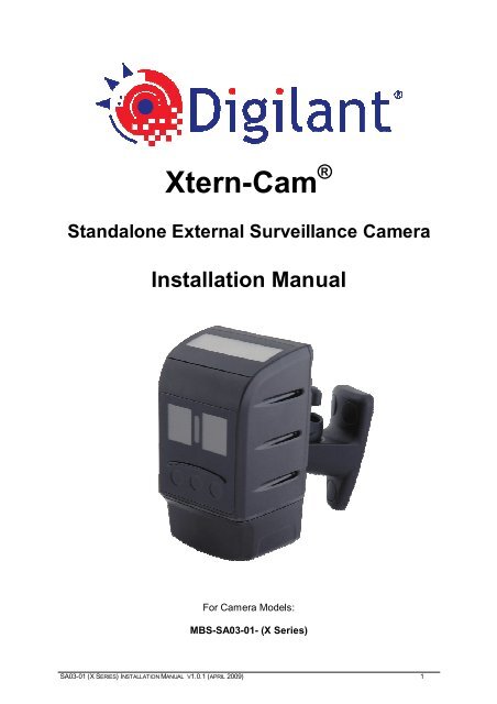
Xtern-Cam ®Standalone External Surveillance Camera<strong>Installation</strong> <strong>Manual</strong>For Camera Models:MBS-<strong>SA03</strong>-<strong>01</strong>- (X <strong>Series</strong>)<strong>SA03</strong>-<strong>01</strong> (X SERIES) INSTALLATION MANUAL V1.0.1 (APRIL 2009) 1
WARNING• This Camera is installed at owners own risk. The owner of this camerashould check all state and federal privacy laws, if existing, prior to using andoperating this device.• This Camera and optional battery charger must only be operated withgenuine battery packs, sourced and supplied by Moreton Bay Systems(MBS). The substitution and consequent use of any other battery pack willnot only void the warranty but could cause serious injury if the battery packignites or explodes.• MBS shall not be held liable of any misuse or unlawful operation of thisproduct.NOTICENo part of this material may be reproduced or duplicated in any form or by anymeans without the written permission of Moreton Bay Systems. Moreton BaySystems reserves the right to make changes to this material without notice.Moreton Bay Systems does not assume any liability of any kind arising out ofinaccuracies contained in this material or due to its application.The product is designed to detect moving objects and capture images. It can also beconnected to a third party alarm system. Being only a part of a security system,Moreton Bay Systems is not responsible for any damages or other consequencesresulting from an intrusion.All other product names mentioned herein are trademarks and/or registeredtrademarks of their respective companies.© MORETON BAY SYSTEMS 2009, All rights reserved.<strong>SA03</strong>-<strong>01</strong> (X SERIES) INSTALLATION MANUAL V1.0.1 (APRIL 2009) 2
TABLE OF CONTENTSLIST OF FIGURES 4INTRODUCTION 5OVERVIEW 5SPECIFICATIONS 6SURVEILLANCE CAMERA 8ACCESSORIES 9INSTALLATION 10GETTING STARTED 10CHOOSING A CAMERA LOCATION 14EXTERNAL TRIGGER 16CAMERA OPERATION 17CAPTURED IMAGES AVAILABLE 18CAPTURING AN INSTANT IMAGE 18OTHER LED PATTERNS 18CHOOSING AN IMAGE SEQUENCE 19MEMORY CARD 20MEMORY CARD CAPACITY 20MEMORY CARD FORMATTING 21MEMORY CARD CONTENTS 21BATTERY OPERATION 23BATTERY POWERED CAMERA AND REMOTE CONTROL 23RECHARGING THE BATTERY 24BATTERY LIFE 25PC SOFTWARE 28TROUBLE SHOOTING 29APPENDIX A:SECURITY SYSTEM INSTALLATION 31APPENDIX B: LED PATTERNS 33DECLARATION OF CONFORMITY 35DISPOSAL OF ELECTRONIC PRODUCTS IN EU 35<strong>SA03</strong>-<strong>01</strong> (X SERIES) INSTALLATION MANUAL V1.0.1 (APRIL 2009) 3
LIST OF FIGURESFigure 1 – Front & Rear of Case, Camera and Battery Access, & Mounting Options...........................8Figure 2 - Accessories.........................................................................................................................9Figure 3 - Formatting the memory card.............................................................................................21Figure 4 - Rapid Battery Charger ......................................................................................................24Figure 5 - Camera Setup Software.....................................................................................................28Figure 6 - <strong>Security</strong> System Wiring Examples ....................................................................................31Figure 7 - Armed and External Trigger Wiring..................................................................................32<strong>SA03</strong>-<strong>01</strong> (X SERIES) INSTALLATION MANUAL V1.0.1 (APRIL 2009) 4
INTRODUCTIONOVERVIEWThe Xtern-Cam ® is a Solar powered outdoor digital surveillance camera with nightvision that captures images when motion is detected within its field of view. Theimages are stored on a removable memory card for easy viewing on a computer.For fast and easy setup, the camera comes pre-configured with all the settingsrequired for standalone surveillance operation and only needs the date and timeto be set. This document outlines the steps involved with installing and using thecamera based on these settings.Please read this entire manual before using the camera in order to get themost out of its features and functions.A complete set of <strong>Installation</strong> and User <strong>Manual</strong>s can be found on the CameraSetup CD in the ‘User <strong>Manual</strong>s’ folder. These documents are also copied into an ‘AllPrograms/Digilant’ folder in the Start Menu during Camera Setup softwareinstallation<strong>SA03</strong>-<strong>01</strong> (X SERIES) INSTALLATION MANUAL V1.0.1 (APRIL 2009) 5
SPECIFICATIONSCamera UnitImage TypeCamera LensesBlack & White or Colour, JPEG compressedVGA (640x480pixels), QVGA (320x240)Wide angle: 3.3mm, AOV: 73°(D) x 61°(H) x 47°(V)Telephoto: 16mm, AOV: 17°(D) 8mm, 40°(D)Image Sensor Sensitivity Colour: 3.8 V/Lux-sec, B&W: 4.9 V/Lux-secMotion Sensor (PIR)Range: 0-5m (16’) (Typical), 0-7.5m (25’) (Maximum)FOV: 38˚ horizontal, 22˚ verticalInbuilt Flash options Type: Invisible IR LED Range: 0-3 m (9.8’)Type: Visible IR LED Range: 0-5 m (16.4’)Inbuilt Solar PanelPower output = 0.17W (Full sunlight)Memory CardMMC Card (v4.2) or SD Card (v1.1), FAT16 file formatStorage Capacity (B&W) 2GB Memory Card VGA: 65,000 images, QVGA: 65,000imagesExternal Power Supply(Battery must be connected for IR spot)Internal Battery CapacityPower Consumption5 VDC, 300mA9VDC to 24V DC, 300 mA (with optional interface board)Very high Capacity (VHCB) – Lithium Ion, 3.7V 7.5AhStandby: 1.9 mA , Running: 100 mA, with IR: 900 mACase Dimensions & Rating 84 x 144 x 72 mm (3.3” x 5.7” x 2.8”), IP 65Weight350g (12oz) – Including batteryOperating Temperature -20˚C to +60˚C (-4˚ F to 140˚ F)PC Software RequirementsWindows 2000 (SP4), Windows XP (SP2), Windows VistaRemote ControlTransmission typeOperating distanceBatteryDimensionsWeightOperating TemperatureInfrared0 – 5m (typical)12V Alkaline, type 23A57 x 37 x 16 mm26 g (Including battery)0˚C to 50˚CRapid Battery ChargerExternal Power Supply: 5VDC 1A Regulated (Plug tip polarity +)Maximum Charging Current800mADimensions90 x 50 x 25 mmWeight44gOperating Temperature:0˚C to 40˚C<strong>SA03</strong>-<strong>01</strong> (X SERIES) INSTALLATION MANUAL V1.0.1 (APRIL 2009) 6
Multi Purpose Interface BoardRatingSymbol ValueUnitMin Typ MaxInput voltage range V IN 9 - 24 VMaximum input current range 1 I IN_MAX 70 - 185 mAMinimum input current range 2 I IN_MIN 33 - 89 mARegulated output voltage 3 V OUT 4.96 - 4.98 VMaximum input current 4 I IN_MAX - - 195 mAMaximum supply current w’ no load I IN_NOLOAD - - 2.5 mAMaximum switching current I SWITCH - - 250 mAMaximum voltage at trigger terminal V TRIGGER_MAX - - 0 VMaximum voltage at arm terminal V ARM_MAX - - 0 VMaximum voltage at relay terminal V RELAY_MAX - - 60 VMaximum current at relay terminal I RELAY_MAX - - 240 mAMaximum voltage at tamper terminal V TAMPER_MAX - - 60 VMaximum current at tamper terminal I TAMPER_MAX - - 240 mAMaximum voltage at siren terminal V SIREN_MAX - - 60 VMaximum current at siren terminal I SIREN_MAX - - 240 mAMaximum voltage at strobe terminal V STROBE_MAX - - 60 VMaximum current at strobe terminal I STROBE_MAX - - 240 mAOperating temperature range T -10 - +65 °CPiezo Buzzer sound pressure level @ 10cm SPL P - 88 - dBAPCB Weight W - - 30 gPCB Width DIM W - 58 - mmPCB Height DIM H - 46.4 - mmInfra-Red Spotlight BoardRatingSymbol ValueUnitMin Typ MaxSupply voltage range V BATT 3.5 - 4.2 VInput current, full I IN_FULL - - 720 mAInput current, step I IN_STEP - - 360 mAInput current, standby I IN_STANDBY - - 0.15 mAOperating temperature range T -10 - +70 °CLED wavelength(SFH4230) λ - 850 - nmLED wavelength(SFH4231) λ - 940 - nmLED half angle ψ - +-60 - °PCB weight W - - 10 gPCB width DIM W - 61.25 - mmPCB height DIM H - 30.5 - mmSolar PanelSymbol Description Value UnitV OC Open circuit voltage 5.67 VoltsV MPP Voltage at max. power point 4.545 VoltsI SC Short Circuit Current 42.0 mAI TYP Typical current at P MMP 39.0 mAη Efficiency 17 %W Weight 11 gDIM W Width 66.0 mmDIM H Height 30.4 mm<strong>SA03</strong>-<strong>01</strong> (X SERIES) INSTALLATION MANUAL V1.0.1 (APRIL 2009) 7
SURVEILLANCE CAMERASolar PanelAdjustable MountingBracketIR SpotlightsStatus LED& RemoteReceiverMotion SensorImage SensorTear Drop for screw- headmounting on a wallCable-Tie slots forMounting on poles or treesON-OFFSwitchFlush MountingWall BracketCardActivityLEDONSD CardBatteryConnectorBattery – Move forward todrop down and remove!Hex Screws to remove bottomcover for access to Camera boardDO NOT OVER-TIGHTEN!FIGURE 1 – FRONT & REAR OF CASE, CAMERA AND BATTERY ACCESS, & MOUNTING OPTIONS<strong>SA03</strong>-<strong>01</strong> (X SERIES) INSTALLATION MANUAL V1.0.1 (APRIL 2009) 8
ACCESSORIESRapidBattery ChargerRemote ControlCameraSetupsoftwareCDFlush MountingWall BracketMemory CardUSB Memory Card ReaderXtern CameraAllen KeyDC Power Supply7.5Ah BatteryFIGURE 2 - ACCESSORIES*Accessories may vary from those pictured here<strong>SA03</strong>-<strong>01</strong> (X SERIES) INSTALLATION MANUAL V1.0.1 (APRIL 2009) 9
INSTALLATIONGETTING STARTEDStep 1 – Recharge the battery1 Connect power supply5Vdc3Wait up to 13 hours forrecharger LED to go fromred to green2Connect batteryFor more information on battery operation, refer to page 23.Step 2 – Install Camera Setup Software1Insert CD2Follow screen prompts to installsoftware3Insert memory card reader4Start program using thedesktop short cut<strong>SA03</strong>-<strong>01</strong> (X SERIES) INSTALLATION MANUAL V1.0.1 (APRIL 2009) 10
Step 3 – Obtain current camera settings3Wait up to 30s until 1 greenblink per motion trigger2Turn on PowerswitchON1Remove the casebottomand InsertSD card4**Remove SD card**If the Xtern-Cam does not have a remote control unit and remotereceiver board, the power switch must be turned off to DISARM theCamera before removing the SD card!After removing the card from the camera it will contain a file with settings in it. Theformat of the contents of this file is critical to the camera operating correctly andshould only be changed using Camera Setup software.If the settings file has been modified via a third party editor and the camera does notfunction properly, delete settings.txt from the card and repeat step 5. A new filecontaining the current settings will be automatically generated by the camera.Step 4 – Set Camera Date and Time1Ensure memory card containscurrent camera settingsStep 3 - Obtain current camera settings2Insert card in reader3Start Camera Setupsoftware and select‘Configuration’ (Default)then click on ‘Continue’<strong>SA03</strong>-<strong>01</strong> (X SERIES) INSTALLATION MANUAL V1.0.1 (APRIL 2009) 11
4Locate memory cardMicrosoft Windows oftencalls memory card drives“Removable Disk”5Select “SETTINGS.TXT” oncard then click on ‘Open’6789Select ‘Computer Time’Sets (Default) date and time for the timestamp that is in text overlay atthe bottom of all imagescaptured by the cameraEnter camera locationdescriptionThis description will appear inthe text overlay at the bottomof all images captured by thecameraSave changes to the memorycardInsert card immediately into cameraIn order to preserve date and timeaccuracy, the card should be insertedinto camera with camera power ONimmediately after the settings changesare saved to card.Date and time are maintained by the camera when switched OFF via the powerswitch.<strong>SA03</strong>-<strong>01</strong> (X SERIES) INSTALLATION MANUAL V1.0.1 (APRIL 2009) 12
Step 5 – Capture and view a test imageStatus LED flashes orange for 2 seconds1 Press middle (blue) buttonTestimageTest images are stored on the memory card in a folder named DCIM and under thatare directories named xxxDIR00 where xxx is a number from 100 - 999. The folderwith the largest number contains the most recent images.MostrecentfolderTestimagesWith the test image(s) displayed in the Camera Setup Image Viewer, rereadChoosing A Camera Location (page 14) and ensure that the camera is installed inthe most ideal location.Step 6 - Arm the CameraThe camera operates like a home security system. It has to be armed by the userbefore the motion sensor can trigger any image captures. Refer to the followingsection ‘Camera Operation’ for information on how to arm and disarm the camerausing the remote control.<strong>SA03</strong>-<strong>01</strong> (X SERIES) INSTALLATION MANUAL V1.0.1 (APRIL 2009) 13
CHOOSING A CAMERA LOCATIONThe camera utilises still-image digital photography technology. As with any othercamera, consideration should be given to the desired image subject matter withrespect to light conditions, target person’s movement, and distance. Similarly, thoughtshould be given to the motion sensor operation to ensure that the target person is stillwithin the camera’s field of view when the image is captured.Prior to installing a camera consider the following factors:1. Direction and amount of available lightTo achieve the highest quality images,ensure that the area being monitored iswell lit and that any ambient light (egfrom sun or street light) is behind thecamera. Having a light source in front ofthe camera will result in the imagehaving extra white in it as well as detailbeing lost in darker, unlit areas.2. Direction of movementIf movement is across the field of view,say, left to right, then some imageblurring will occur in low lightconditions such as dawn or dusk. Also,the motion sensor is least sensitive formovement directly towards the camera.If possible, it is best to position thecamera such that target person walks ata slight angle to its field of view.3. Target locationThe camera takes highest qualityimages when the target person isstill or paused. Consider the layoutof the target area and point thecamera where the target person ismost likely pause or stand still eg infront of a valuable item or at a gateor door.LightBehindcameraIn front ofcameraMovementPersonmovingPersonmovingPerson pauses atvaluable object<strong>SA03</strong>-<strong>01</strong> (X SERIES) INSTALLATION MANUAL V1.0.1 (APRIL 2009) 14
4. Distance to targetFor detailed facial recognition, thecamera’s optimal distance to target is upto 5m. If the target person is too faraway from the camera then someresolution detail may be lost. However,details such as colour, hair style, andclothing style will still be identifiable.5mImages taken with infra-red will havepoorer resolution with distance thanimages taken in full daylight.5. Angle of visionThe motion sensor detects a larger angleof vision than shown in the cameraimages. To prevent false triggers careshould be taken to point the such thatthere is no high traffic area 10 o eitherside or above or below a test image.70 o10 o10 oField of view:Motion sensor 90 o horizontal, 35 o below horizontalCamera 70 o horizontal, 40 o vertical6. Temperature variationMotion detection works by monitoringfor temperature differences caused bya target person’s movement and thebackground temperature. Avoidpointing the camera at sources oftemperature changes such as pets.Temperaturevariation<strong>SA03</strong>-<strong>01</strong> (X SERIES) INSTALLATION MANUAL V1.0.1 (APRIL 2009) 15
EXTERNAL TRIGGERThe external trigger input is an alternative means of triggering the camera other thanthe motion sensor.This feature is only available with the optional Multi Purpose Interface Board.The External trigger can be connected to doors, windows, cash registers etc. Thecamera can monitor both the external trigger and internal motion sensorsimultaneously or the motion sensor can be disabled leaving the external trigger tostart Event-Triggered image capture sequences.By default, the external trigger is activated when it connects to 0V. This operation canbe changed to trigger on an open circuit using the Camera Setup software.As is the case with the motion sensor, the camera must be armed before the externaltrigger will start an Event-Triggered image capture sequence.For external trigger wiring instructions, refer to Appendix A, Figure 7.<strong>SA03</strong>-<strong>01</strong> (X SERIES) INSTALLATION MANUAL V1.0.1 (APRIL 2009) 16
CAMERA OPERATIONThe camera will only capture images whenit is armed.Arming and disarming the camera can be doneeither by using the remote control, or by usingexternal arm input wiring, or via the camerasoftware’s scheduler feature.When the camera is not armed, the status LEDwill flash green for one second each timemotion is detected.Arming the CameraArm (Red)Capture Image (Blue)Disarm (Black)1 secGreenMotion sensor activation when disarmedWhen the camera is arming the status LED willrapidly flash red for 5 seconds.30 sec5 secSystemArmedUpon arming, the camera will capture and write an“arm” image to the memory card. It will also keepthe motion sensor disarmed for 30 seconds toenable the user to move out of range.Once the camera is armed, the LED will flash redfor one second each time motion is detected.Disarming the CameraTo disarm the camera, point the remote controlat the camera unit and press the right (black)button. If there is no remote control, turn thepower switch off to DISARM the camera. TheLED will rapidly flash green for 5 seconds, coincidentallythe Card Activity LED will stayRED for 5 seconds or until the SD card is safeto be removed. The Card Activity LED indicatesthat data is being written to the SD Card.R R R R R R RArming the camera1 secRedMotion sensor activation when armed> 5 sec SystemDisarmedG G G G G G GDisarming the camera5 secondsRedCard Activity LEDA memory card can be corrupted if it isremoved whilst the camera is writingimages to it. Only remove the memorycard after the Card Activity LED isextinguished. Do not remove the cardwhile the camera is armed.If a card is corrupted because of earlyremoval then it can be reformatted andreused. Refer to the <strong>Installation</strong> <strong>Manual</strong>for information on how to reformat acard.Card RemovalArming,Disarming orArmedDisarmedCard ActivityLED<strong>SA03</strong>-<strong>01</strong> (X SERIES) INSTALLATION MANUAL V1.0.1 (APRIL 2009) 17
CAPTURED IMAGES AVAILABLEAfter disarming, if the camera has captured anyimages whilst armed then it will indicate thatimages are available by flashing orange in 1second pulses. The camera will also show thesame orange flash sequence if the card is notinserted.1 secO O O OCaptured images areavailable on memory card, orcard not inserted.CAPTURING AN INSTANT IMAGETo force the camera to capture an image independent of the motion sensor, point theremote control at the camera unit and press the middle (Blue) button.Status LED2 secOrangeTest image1 Press middle (blue) buttonOTHER LED PATTERNSDate and Time not setFast orange flashing for 3 seconds. Thissequence occurs on power up after the systemhas loaded.O O3 secO O O O OSystem is loadingConstant orange until loading has completed.Do not remove memory card while the system isloading.Critical ErrorConstant red LED. Remains active until error isfixed. Turn power off, then on again. If LED staysred again, contact your distributorOn until safe to removeOrangeOn until error is fixedRed<strong>SA03</strong>-<strong>01</strong> (X SERIES) INSTALLATION MANUAL V1.0.1 (APRIL 2009) 18
CHOOSING AN IMAGE SEQUENCEThe choice of image capture sequence could mean the difference between catchingsomeone in the act and catching his or her shadow. The camera’s default settings aredesigned for a single image per capture sequence per motion trigger. This maximizesthe rate of image capture to card whilst keeping the time lag between sequences to aminimum. However, this may not always be the preferred installation.For optimum use of the camera’s many advanced features the user is stronglyrecommended to read the ‘Choosing An Image Sequence’ section of the camera’s usermanual. Experimenting with various features such as capturing images prior tomotion detection (pre-trigger), capturing multiple images per motion trigger (eventtrigger),and capturing images based on a timer (time-lapse) should be considered.<strong>SA03</strong>-<strong>01</strong> (X SERIES) INSTALLATION MANUAL V1.0.1 (APRIL 2009) 19
MEMORY CARDThe camera will accept both MMC and SDmemory cards ranging from 32MB to 2GB with theFAT16 file format. SDHC TM cards are notsupported.SD TM /MMC TM32MB –2GBSDHC TMWhen the images have been copied from thememory card to the computer, remember to makeroom for new images by deleting the old ones from the card before inserting it backinto the camera.MEMORY CARD CAPACITYThe number of images that a memory card can store is dependent upon a number offactors:o Size of image resolution being captured – high or mediumo Whether the text overlay feature is enabled or disabledo The JPEG compression performance varies depending upon image content. Thisvariation results in varying file sizes.The table below lists estimate card capacity values based on assumption that averageimage size is 32kB high and 10kB medium resolution black and white images:Card Capacity High Resolution Medium Resolution32 MB 1000 300064 MB 2000 650<strong>01</strong>28 MB 4000 13000256 MB 8000 21500512 MB 16000 3270<strong>01</strong> GB 32000 650002 GB 65000 65000TABLE 1 – MEMORY CARD CAPACITY<strong>SA03</strong>-<strong>01</strong> (X SERIES) INSTALLATION MANUAL V1.0.1 (APRIL 2009) 20
MEMORY CARD FORMATTINGIn the rare case that the memory card has been corrupted, it may be necessary toreformat the card. The memory card must be formatted with FAT16 file system.Must be FAT (not FAT32)FIGURE 3 - FORMATTING THE MEMORY CARDTo format the memory card with FAT16 file system:1. Insert the memory card into the USB reader and plug the reader into a USB porton the computer.OPEN MY COMPUTER, RIGHT CLICK THE REMOVABLE DISK CONTAINING THE MEMORY CARDAND CLICK FORMAT… THIS WILL BRING UP THE FORMAT REMOVABLE DISK WINDOW IN2. Figure 3.3. Select FAT (not FAT32) in the File System box and click Start.MEMORY CARD CONTENTSThe camera uses the memory card to obtain user modified settings and also for storingimages after they have been captured and compressed.The following files may be present on the memory card after operating the camera:- Eventlog.txt Event log- Settings.txt Settings File- Startup.jpg Startup Image- XXXDIR00 Image Directories- XXXXX.JPG Image files- XXXXX.ENC Encrypted Image files- Stats.txt Statistics file- Syslog.txt System log- Version.txt Version fileEvent LogThe event log is created the first time a memory card is inserted in the camera, oranytime there is no event log present. It is a log of the time and date of major eventsoccurring in the camera. For example, it records the time and date each image iswritten to the memory card, when the camera is armed or disarmed, and if motion isdetected or not etc. It also displays the battery capacity each time the camera is armedor disarmed, so that the user knows when to recharge the battery.<strong>SA03</strong>-<strong>01</strong> (X SERIES) INSTALLATION MANUAL V1.0.1 (APRIL 2009) 21
Settings FileThe settings file is used to configure the camera. It is read each time the memory cardis inserted. If a memory card with no settings file is inserted, the camera creates onewith a readout of its current settings. The settings file is modified using the CameraSetup software which is run on a computer by the user to configure the camera.The Camera Setup Software provides a user friendly interface for configuring thecamera settings.The format of the contents of the settings file is critical to the camera operating correctlyand should only be changed using Camera Setup software. If the file has been modifiedvia a third party editor and the camera does not function, erase the settings file from the memorycard and insert the memory card into the camera. The settings file will be automaticallyregenerated with the camera’s current settings. The Camera Setup software can now be used toedit the settings.Startup ImageEach time the memory card is inserted into the camera, the camera reads the settingsfile and then captures a startup image (STARTUP.JPG). This image can be viewed toverify that the camera is functioning correctly.Image DirectoriesImages are stored on the memory card in a folder named DCIM under under which aresub-directories named xxxDIR00 where xxx is a number from 100 - 999. A newdirectory is created every time the camera restarts or the memory card is removed. Thecamera will also automatically create a new directory if the contents of the directoryreach 5% of the card capacity, or if the number of images in the directory reaches 500.If the numerical part of the directory name reaches 999, the camera renames alldirectories so that the directory with the lowest numerical part becomes 100DIR00,the next lowest becomes 1<strong>01</strong>DIR00 etc.When the memory-overwrite option is enabled (default) and the memory card hasbeen filled up with images, the oldest directory is removed thus freeing memory fornewly captured images.Image FilesImages are named with a numerical sequence. The most recent images are alwayslocated in the directory whose name contains the largest numerical part. The imagenumber starts from zero each time the memory card is removed or the power is reset.The alphabetic suffix in the image name indicates the type of image.Stats.txt, Syslog.txt, Version.txtThese hidden files may be used by service personnel and contain no informationrelevant to the user. The camera will function normally without these files present.<strong>SA03</strong>-<strong>01</strong> (X SERIES) INSTALLATION MANUAL V1.0.1 (APRIL 2009) 22
BATTERY OPERATIONBattery life of a camera is usage dependent.Very High Capacity Battery (Colour Camera – no IR spotlight or Solar panel22 weeks standby, or15 weeks at 200 images/day, or8 weeks at 800 images/dayBattery capacity is recorded in the camera’s event log every time the camera is armedor disarmed.When powered solely by battery, the camera preserves battery life by performing anumber of power saving procedures. These procedures include powering down theimage sensor when it is not in use. When an image capture is triggered the imagesensor is powered up again. In these cases, sometimes the auto exposure may take alittle longer to fully adjust to the lighting conditions and so the first image in asequence may appear slightly over or under exposed.Lithium-Ion cells and battery packs may get hot, explode or ignite and cause seriousinjury if exposed to abusive conditions. Be sure to follow the safety warnings listed below.• Do not install the battery backwards so the polarity is reversed.• Do not connect the positive terminal and negative terminal of the battery to each other withany metal object (such as wire).• Do not place the battery in a fire or heat the battery.• Do not pierce the battery with nails, strike the battery with a hammer, step on the battery orotherwise subject it to strong impacts or shocks.• Do not solder directly onto the battery.• Do not expose battery to water or salt water, or allow the battery to get wet.• In the event the battery leaks and the fluid gets into an eye, do not rub the eye. Rinse wellwith water and immediately seek medical care. If left untreated, the battery fluid could causedamage to the eye.BATTERY POWERED CAMERA AND REMOTE CONTROLTo arm or disarm a camera that is solelypowered by battery, first wave your hand toactivate the motion sensor then use theremote. The camera’s infra-red receiverremains active for 5 seconds after motion isdetected.<strong>SA03</strong>-<strong>01</strong> (X SERIES) INSTALLATION MANUAL V1.0.1 (APRIL 2009) 23
RECHARGING THE BATTERYIf the camera has external power connected via the 9Vdc DC plug or 12VDC terminalstrip then the camera will start charging as soon as power is applied. When long termsurveillance with a battery powered camera is required, it is useful to have multiplebatteries and a rapid battery charger.FIGURE 4 - RAPID BATTERY CHARGERThe rapid battery charger’s LED is green when charging and turns red when thebattery is fully charged. The charging times for the 7.5Ah battery are:CameraRapid Battery Charger105 hours 13 hoursTABLE 2 - BATTERY CHARGING TIMES FROM FULLY EMPTYThe above camera charging time was calculated with the camera switched off.Charging will also take place with the camera unit operating but at a slower rate.<strong>SA03</strong>-<strong>01</strong> (X SERIES) INSTALLATION MANUAL V1.0.1 (APRIL 2009) 24
BATTERY LIFEThe resolution of the images and the frequency of capture all determine the powerconsumption of the Camera. The following examples give four scenarios of battery life:1. Xtern-Cam (Colour or B&W)The maximum available capacity of the very high capacity battery is 7500mAh whichgives an operational standby of 22 weeksThe following formula can be used for typical battery life calculation:BL = 0.95 Bc .0.0327 Tn In Rs + 45.6Where:BL = Battery Life (days)Bc = Battery Capacity (mAh)Tn = No. of triggers per dayIn = No. of images per triggerRs = Resolution factor ie. high (VGA) = 2.9, medium (QVGA) = 1For example, using a camera set up of 1 high resolution image per capture sequenceand assuming that the camera is triggered on average 200 times per day, the batterywould last for 110 days (15 weeks) with 22,000 images stored on the memory card.Alternatively, if the camera captures 800 high resolution images per day, then thebattery would last for 58 days (8.4 weeks). Depending upon card size, up toapproximately 65,000 images can be stored on a memory card at any one time.2. Xtern-Cam (Colour or B&W with Solar Panel)The Solar panel performance is directly dependent on the number of hours ofsunshine per day (S H) and the sun’s intensity (S I) (ie full direct sunshine or cloudy).In cloudy conditions, the solar panel should at least provide the standby current forthe Camera. For this calculation we will assume: Average Sunlight: S H = 9, S I = 70%The following formula can be used for typical battery life calculation:BL = 0.95 Bc .0.0327 Tn In Rs + 45.6 – (I SP S I S H)Where:BL = Battery Life (days)Bc = Battery Capacity (mAh)Tn = No. of triggers per dayIn = No. of images per triggerRs = Resolution factor ie. high (VGA) = 2.9, medium (QVGA) = 1I SP = Solar Panel current at Full Sunlight = 39mAS I = Sun Intensity (Average) = 70%S H = Sunlight hours/day (Average) = 9<strong>SA03</strong>-<strong>01</strong> (X SERIES) INSTALLATION MANUAL V1.0.1 (APRIL 2009) 25
The Solar panel enables the Camera to have infinite standby ie Never need to rechargebattery!The Camera can capture up to 2110 images per day without requiring the battery tobe rechargedAlternatively, if the camera captures 5000 high resolution images per day, then thebattery would last for 26 days (3.7 weeks). Depending upon card size, up toapproximately 65,000 images can be stored on a memory card at any one time.3. Xtern-Cam (B&W with IR Spotlight)The maximum available capacity of the very high capacity battery is 7500mAh whichgives an operational standby of 22 weeksThe following formula can be used for typical battery life calculation:BL = 0.95 Bc .0.0843 Tn In Rs + 45.6Where:BL = Battery Life (days)Bc = Battery Capacity (mAh)Tn = No. of triggers per dayIn = No. of images per triggerRs = Resolution factor ie. high (VGA) = 2.9, medium (QVGA) = 1For example, using a camera set up of 1 high-resolution image per capture sequenceand assuming that the camera is triggered on average 200 times per day, the batterywould last for 75 days (10 weeks) with 15,000 images stored on the memory card.Alternatively, if the camera captures 800 high-resolution images per day, then thebattery would last for 29 days (4 weeks).Depending upon card size, up to approximately 65,000 images can be stored on amemory card at any one time.<strong>SA03</strong>-<strong>01</strong> (X SERIES) INSTALLATION MANUAL V1.0.1 (APRIL 2009) 26
4. Xtern-Cam (B&W with IR Spotlight and Solar Panel)The Solar panel performance is directly dependent on the number of hours ofsunshine per day (S H) and the sun’s intensity (S I) (ie full direct sunshine or cloudy).In cloudy conditions, the solar panel should at least provide the standby current forthe Camera. For this calculation we will assume:Average Sunlight: S H = 9, S I = 70%The following formula can be used for typical battery life calculation:BL = 0.95 Bc .0.1357 Tn In Rs + 45.6 – (I SP S I S H)Where:BL = Battery Life (days)Bc = Battery Capacity (mAh)Tn = No. of triggers per dayIn = No. of images per triggerRs = Resolution factor ie. high (VGA) = 2.9, medium (QVGA) = 1I SP = Solar Panel current at Full Sunlight = 39mAS I = Sun Intensity (Average) = 70%S H = Sunlight hours/day (Average) = 9The Solar panel enables the Camera to have infinite standby ie Never need to rechargebattery!The Camera can capture up to 818 images per day without requiring the battery to berechargedAlternatively, if the camera captures 1000 high-resolution images per day, then thebattery would last for 44 days (6 weeks). Depending upon card size, up toapproximately 65,000 images can be stored on a memory card at any one time.<strong>SA03</strong>-<strong>01</strong> (X SERIES) INSTALLATION MANUAL V1.0.1 (APRIL 2009) 27
PC SOFTWAREThe Xtern-Cam camera settings can be customised using Camera Setup software on aPC. It can be used to configure the camera and view images and event logs.FIGURE 5 - CAMERA SETUP SOFTWAREFor more information, refer to the Camera Setup user manual.<strong>SA03</strong>-<strong>01</strong> (X SERIES) INSTALLATION MANUAL V1.0.1 (APRIL 2009) 28
TROUBLE SHOOTINGSymptomStatus LED flashes orangeonce per second.Status LED stays red for aprolonged period of time.Possible Solutions• Check the memory card. Reasons for flashing include:o The camera has captured some images sincethe last time it was armed.o The memory card is not inserted.o There is a message in the camera’s Event Logthat needs to be read.o The camera could not read the settings.txt file.Check its contents for error.Refer to Camera Setup software user manual forinformation about messages in the event log.• If there are no files on the memory card, ensure thatthe memory card is an MMC or SD and has beenformatted with FAT16 file format (page 21).Critical error. Turn power off, then on again. If LED staysred again, contact your distributor.Images appear blurred • Increase the amount of light in the scene beingmonitored. Reconsider the camera installationlocation. Refer to the Choosing A Camera Locationsection (page 14) for more information.Images appear bright ordark.Camera does not respondto remote control.Camera automaticallyarms when the memorycard is inserted.• If powered by battery, the power saving mode of thecamera may cause the first image in a sequence to beunder or over exposed.• Camera may be facing direct sunlight or a bright light.Ensure that a majority of the light source is behindthe camera. Reconsider the camera installationlocation. Refer to the Choosing A Camera Locationsection (page 14) for more information.• Computer LCD screens vary considerably with angleof vision. Ensure that the screen is being viewed fromdirectly in front and try moving the LCD in verticalaxis to improve contrast.• Some computer screens are not well calibrated. Tryadjusting the screen’s contrast setting to increasedetail in the image’s dark or bright areas.• Check the health of the battery in remote control• If camera is powered by battery, the power savingmode of the camera disables the infrared receiveruntil the motion sensor is triggered. Move in front ofthe camera and try again.• A camera will only respond to its matching remote. Ifmore than one camera is in use, check that thecorrect remote control is being used.• The memory card may have been removed while thecamera was armed. If the memory card contains theirarmed.txt file, remove it. If not, delete thesettings.txt file and the automatic arming will cease.• Make sure that the Arm when contact is setting iscorrect. If not connected to an alarm system, this<strong>SA03</strong>-<strong>01</strong> (X SERIES) INSTALLATION MANUAL V1.0.1 (APRIL 2009) 29
Alarm relay is constantlyactivated.When the camera ismounted outdoors, thememory card is being filledquickly with images thatdon’t appear to have beenmotion triggered.setting should be closed.• If the camera is powered via an external 12Vdc powersource connected to the terminal strip, check thepolarity of the wiring.• Check the camera’s event log for an error message.• If there is no error message and the memory overwriteoption is disabled, the memory card may be full.• Motion sensors are heat sensitive devices. Warm airmovement and wind can therefore trigger false imagecapture sequences.ooReduce the camera’s Sensitivity settingEnable the camera’s Image Sequence Delaysetting. This will force the camera to confirm themotion before capturing images.• The camera’s motion sensor angle of detection isgreater than the field of vision of the lens andtherefore movement just outside the lens field ofvision can trigger “false” triggers. Refer to theChoosing A Camera Location section (page 14) formore information.The camera is failing todetect movement or is tooslow to detect movementAll the settings exceptDate/Time are grey in thePC software.Some of the settings aregrey in the PC software.• Increase the camera’s Sensitivity setting to 0 or 1• Enable Pre-Trigger mode setting so the cameracaptures time based images prior to detection ofmovement. Note that pre-trigger mode increases thestandby current consumption of the camera andtherefore reduces battery life. If the camera is notconnected to an external 12Vdc power source thenconsider using the Scheduler settings to disable thecamera (and therefore Pre-Trigger mode) during nightand poor light conditions.• The Camera Setup software is unable to detect orread the camera settings from the memory card thenit disables all settings by making them grey. If asettings.txt file exists on the card, delete it then insertinto the camera to obtain a new settings file withcurrent settings.• If the Camera Setup software is newer than thecamera internal software then it may support settingsthat are not available in the camera. The PC softwareautomatically detects supported settings and disablesunsupported settings by making them grey.• Some settings have inter-dependence upon othersettings. If a setting is not valid because anothersetting has been set, the PC software automaticallydisables it. For example, the siren/strobe time aftertrigger and duration settings are dependent upon thesiren/strobe module support being enabled/disabled.TABLE 3 - TROUBLESHOOTING GUIDE<strong>SA03</strong>-<strong>01</strong> (X SERIES) INSTALLATION MANUAL V1.0.1 (APRIL 2009) 30
APPENDIX A:SECURITY SYSTEM INSTALLATION4 Wire Connectiona) b)External Trigger connections<strong>Security</strong>PanelArmed Zone 0V 12VExternal Trig inputTamperN.CRelayTrig PowerArmed 0V 12VTamperN.CRelayTrig PowerArmed 0V 12VInterfaceBoardDoor or windowswitch used asexternal trigger *2K2InterfaceBoardEnd of lineresistor* The external trigger input is set up for a normally o penswitch by default. This can be chan ged fo r a no rmallyclosed switch via the setup software..FIGURE 6 - SECURITY SYSTEM WIRING EXAMPLESBefore installing the camera to a security system it is recommended that users readthe ‘Choosing A Camera Location’ section (page 14) for more information aboutobtaining optimal quality images from the camera.To add an Xtern-Cam to an existing security system:1. Disconnect power to the security system, including the battery.2. Turn off the Camera and remove the battery.3. Remove the rear case of the Camera.4. Carefully plug in the Interface board to the Camera board and secure with 2 screwsat the top.5. Create a hole for the security wires in the rear case.If the camera is being installed outdoors then care should be taken to ensure that thecase’s weatherproof rating is preserved.6. Feed the security system wires through the hole and connect them to therespective terminals on the interface board using one of the reference diagrams inFigure 6The Xtern-cam is a battery operated device. Its battery life can be extended via its onboardrecharge circuitry by wiring to the 12Vdc power supply of an alarm system.However, if installed in a location where it regularly captures a high number of infra-redimages in short periods of time, the power consumption may exceed power recharge, causingthe battery to go flat. The camera will recharge the battery irrespective of its armed ordisarmed state.7. If the camera is to be triggered by an external source such as a door, window orgate, wire the external switch between 0V and the External trigger input on theinterface board’s screw terminal strip (see Figure 7). If required, it is possible to usethe Camera Setup software to disable the motion sensor and/or configure theexternal trigger’s normally closed/normally opened switch type.<strong>SA03</strong>-<strong>01</strong> (X SERIES) INSTALLATION MANUAL V1.0.1 (APRIL 2009) 31
8. Screw the rear case back on to the Camera ensuring the seal is properly in place.9. Mount the Camera using the mounting bracket and set the correct Camera angle.10. Insert and connect the battery and turn the Camera power on.11. Re-connect the power to the security system.12. Arm the <strong>Security</strong> System and test that the camera triggers the alarm when motionis detected.13. Disarm the camera, remove the memory card and verify that an image sequencewas initiated on the alarm by viewing captured images using the Camera Setupsoftware.14. Set the date and time using the Camera Setup software, re-insert the memory cardand screw on the underside cover.• End of line resistors are required by most security systems. The value of the resistors varydepending on the security system. Consult your security system manual for more information.• The Armed (screw terminal 4) and External Trigger (screw terminal 3) inputs are connected to0V through a switch or contact. These inputs are software configurable via Camera Setupsoftware as either active when the circuit opens or active when circuit closes to 0V.Armed CircuitArmed when opened.Armed when closed.Armed0VArmed0VExternal Trigger CircuitTriggered when opened.Triggered when closed.Triggered0VTrig0VFIGURE 7 - ARMED AND EXTERNAL TRIGGER WIRING<strong>SA03</strong>-<strong>01</strong> (X SERIES) INSTALLATION MANUAL V1.0.1 (APRIL 2009) 32
APPENDIX B: LED PATTERNSThe table below lists all the LED patterns associated with the camera’s normaloperation mode. For more information about status LED modes refer to camera setupsoftware user manual.1 System is loading:ORANGE until loading has completed.Do not remove memory card while thesystem is loading.2 Check the Event Log or No memorycard inserted:ORANGE flash once per second untilmemory card has been removed andre-inserted.On until safe to remove memory card1 sec3 Arming:Fast RED flashing for 5 seconds.System is armed after 30 seconds.5 sec30 secSystem Armed4 Disarming:Fast GREEN flashing for 5 seconds oruntil the last image is written to thememory card.5 sec System DisarmedDo not remove memory card untilflashing has stopped or elsememory card corruption mayoccur.5 Motion sensor or external triggeractivation when ARMED:RED active for 1 second.1 sec6 Motion sensor or external triggeractivation when DISARMED:GREEN active for 1 second.1 sec7 Capture an instant image withremote:ORANGE active for two a seconds.2 sec8 Critical Error: RED, active until erroris fixed.On until error is fixed<strong>SA03</strong>-<strong>01</strong> (X SERIES) INSTALLATION MANUAL V1.0.1 (APRIL 2009) 33
9 Time and Date not set:Fast ORANGE flashing for 3 seconds3 sec10 Memory Card Activity:RED for 5 seconds5 secondsRedCard Activity LEDTABLE 4 - LED PATTERNS<strong>SA03</strong>-<strong>01</strong> (X SERIES) INSTALLATION MANUAL V1.0.1 (APRIL 2009) 34
, ,, ,DECLARATION OF CONFORMITYThis product has been tested and complies with the Class B radiated and conductedEMI requirements of AS/NZS CISPR 22, FCC part 15B, and EN55024.This device complies with Part 15 of the FCC Rules. Operation is subject to thefollowing two conditions:• This device may not cause harmful interference, and• This device must accept any interference received, including interference thatmay cause undesired operationN137341. Changes or modifications to this product that are not expressly approved by themanufacturer could void the user's authority to operate the equipment.2. Electrostatic discharge (ESD) events can harm electronic components inside your Xtern-Cam camera. Under certain conditions, ESD may build up on your body or and object,such as a peripheral, and then discharge into another object, such as your camera. Toprevent ESD, you should discharge electricity from your body before you interact with thecamera internal components. You can protect yourself against ESD by touching a metalgrounded object before interacting with the camera.DISPOSAL OF ELECTRONIC PRODUCTS IN EUIn the European Union, the crossed out wheel bin symbol below is attached to aproduct it means it is covered by the European Directive 2002/96/EC.The European Directive 2002/96/EC states that the last userof all electronic products must not dispose of the product viathe standard municipal waste service. The product must besent to the appropriate collection facilities appointed by thelocal government authority.The correct disposal of your old camera will help preventpotential negative consequences for the environment and human health.For more detailed information about disposal of your old camera, please contact yourcity office, waste disposal service or the shop/distributor where you purchased theproduct.<strong>SA03</strong>-<strong>01</strong> (X SERIES) INSTALLATION MANUAL V1.0.1 (APRIL 2009) 35