
Create successful ePaper yourself
Turn your PDF publications into a flip-book with our unique Google optimized e-Paper software.
123456789012<br />
123456789012<br />
123456789012<br />
123456789012<br />
123456789012<br />
123456789012<br />
123456789012<br />
123456789012<br />
123456789012<br />
123456789012<br />
123456789012<br />
123456789012<br />
123456789012<br />
123456789012<br />
1234567890123<br />
1234567890123<br />
1234567890123<br />
1234567890123<br />
1234567890123<br />
1234567890123<br />
1234567890123<br />
1234567890123<br />
1234567890123<br />
1234567890123<br />
1234567890123<br />
1234567890123<br />
1234567890123<br />
1234567890123<br />
time that the ignition switch is turned on. An exception to this would be if feature<br />
#8 is turned on, and a door being open when the ignition switch is turned on. The<br />
following feature #7 controls the automatic unlocking operations, and feature #8<br />
provides for an override of this automatic locking if a door is open when the ignition<br />
is turned on.<br />
Feature #7 Doors Unlock With Ignition Off<br />
Factory Default Setting On (all doors will unlock)*<br />
(press “III” button to program)<br />
Options:<br />
Off<br />
(press “arm/lock” button to program)<br />
Driver’s Door Only* (press “disarm/unlock” button to program)<br />
All Doors Except Driver’s Door* (press “II” button to program)<br />
Similar to the previous locking feature, except this feature controls the unlock<br />
operations when the ignition is turned off, and it has more options because of the<br />
multiple unlocking outputs of the DLS port.<br />
*Multiple unlock outputs offer the capability of unlocking only the driver’s<br />
door when the system is disarmed (Driver Door Priority Unlocking), and then the<br />
option of unlocking all doors with a second press of the “disarm/unlock” button.<br />
The driver’s door unlocking differently from the other doors must be configured<br />
when the system is installed!<br />
If the system is installed without the Driver’s Door Priority Unlocking interface,<br />
this feature unlocks all of the doors when the ignition switch is turned off.<br />
If Driver’s Door Priority Unlocking is installed, this feature can control only the<br />
driver’s door unlocking when the ignition is turned, all doors unlocking, or all doors<br />
except the driver’s. The following feature provides for an override of this automatic<br />
unlocking if a door is open when the ignition is turned off.<br />
Feature #8 Open Door Bypass of Ignition Locking<br />
Factory Default Setting On (press “arm/lock” button to program)<br />
Option: Off (press “disarm/unlock” button to program)<br />
This feature cancels the automatic locking or unlocking of the vehicle’s doors<br />
should one of the doors be open when the ignition switch is turned on or off.<br />
Feature #9 Confirmation Chirps<br />
Factory Default Setting On<br />
(press “arm/lock” button to program)<br />
Options:<br />
Off<br />
(press “disarm/unlock” button to program)<br />
Chirps Excepting Valet Mode (press “II” button to program)<br />
Chirps in Valet Mode Only<br />
(press “III” button to program)<br />
This feature removes the system’s 1 arming and 2 disarming confirmation chirps.<br />
Page - 26<br />
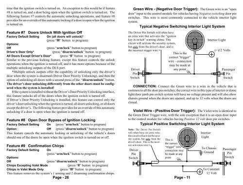
Green Wire - (Negative Door Trigger): The Green wire is an "open<br />
door" input to the control module for vehicles having Negative switching door pin<br />
switches. This wire is most commonly connected to the vehicle interior light<br />
system.<br />
Typical Negative Switching Interior Light System<br />
The Driver Pin Switch will often have<br />
an extra wire that activates the “ignition<br />
key in switch” warning chime. This<br />
circuit will activate the security system,<br />
but only from the driver's door, and is<br />
the incorrect trigger wire ><br />
1 Driver<br />
Pin1<br />
Switch<br />
12<br />
12<br />
12<br />
12<br />
12<br />
12<br />
12<br />
12<br />
12<br />
This is the<br />
correct "trigger”<br />
wire - connection<br />
may be made at<br />
any point<br />
1<br />
12<br />
1<br />
CONNECTION: Connect the Green wire to a wire in the vehicle that is<br />
common to all the door pin switches; the correct wire in this type of interior or dome<br />
light/door jamb pin switch system will have no voltage present and will also show<br />
chassis ground when the doors are opened, and up to 12 volts when the doors are<br />
closed.<br />
Violet Wire - (Positive Door Trigger): The Violet wire is identical to<br />
the Green Door Trigger wire, with the sole exception that it is an open door input<br />
to the control module for vehicles having Positive 12 volt door pin switches.<br />
Typical Positive Switching Interior Light System<br />
Note: The Driver Pin Switch<br />
will often have an extra wire;<br />
this circuit will activate the security<br />
system, but only from the<br />
driver's door. This is the incorrect<br />
activation wire ><br />
Driver<br />
Pin<br />
Switch<br />
1 1<br />
1 1<br />
1<br />
This is<br />
the correct<br />
“trigger” wire -<br />
connection may<br />
be made at any<br />
point<br />
<br />
Page - 11<br />
Interior<br />
Light<br />
Interior Light<br />
To Chassis<br />
Ground<br />
(+)12 Volts<br />
1<br />
1<br />
1<br />
1<br />
1<br />
1<br />
1<br />
1<br />
To Constant<br />
12 Volt<br />
Passenger<br />
Pin<br />
Switch<br />
Passenger<br />
Pin<br />
Switch