
Create successful ePaper yourself
Turn your PDF publications into a flip-book with our unique Google optimized e-Paper software.
Options:<br />
Panic<br />
(press “disarm/unlock” button to program)<br />
4th Channel<br />
(press “II” button to program)<br />
5th Channel<br />
(press “III” button to program)<br />
This feature changes how the controller’s or transmitter’s “III” button operates.<br />
Normal operation, or the default setting, has the “III” button operate the 3rd Channel<br />
output (press the button twice within 5 seconds). This feature allows changing it to<br />
instead operate panic or either of the two other optional channel outputs (see the<br />
Complete Programmable Features Matrix on page 33). Panic can always be<br />
operated, by the alternative methods of pressing either the “arm/lock” and “disarm/<br />
unlock” button for 3 seconds.<br />
Feature #22 Doorlocking Functions<br />
Factory Default Setting .8 Second Lock & Unlock Output<br />
(press “arm/lock” button to program)<br />
Options:<br />
3 Second Lock & Unlock Output (press “disarm/unlock” button to program)<br />
Double Pulse Unlock Output (press “II” button to program)<br />
Total Closure Lock Output<br />
(press “III” button to program)<br />
This single feature gives the installer several needed options, to match the security<br />
system’s doorlocking outputs to suite different vehicle requirements.<br />
• The first setting (programmed by the “arm/lock” button) has the system<br />
produce both the lock and unlock outputs as .8 second in duration. This is the<br />
most common form of output needed, which interfaces most vehicles.<br />
• The second setting (programmed by the “disarm/unlock” button) changes the<br />
lock and unlock outputs to be a longer 3 second pulse output. This is for certain<br />
vehicles which require a longer output pulse from the system’s control unit;<br />
typically <strong>car</strong>s having vacuum pump systems, although the longer setting is also<br />
more suitable in some newer vehicles.<br />
• Some newer vehicles require a double pulse output to remotely unlock the doors<br />
and/or to disarm a factory-equipped security system, which is what the Double<br />
Pulse Unlock setting provides (it is programmed by the “II” button ). The lock<br />
output pulse, in this setting, is .8 second.<br />
• The Total Closure Lock Output (programmed by the “III” button) may be used<br />
with vehicles which are originally equipped with the total-closure feature.<br />
Typically, a total closure feature is when locking the vehicle’s doors if the key<br />
in the door is held to “lock” for a period of time the vehicle will close all<br />
windows and the sunroof, in addition to locking the doors.<br />
Selecting this feature setting changes the system’s door lock output pulse from<br />
a .8 second to as long as a 28 second duration output. The unlock output is 3<br />
seconds in this setting.<br />
Note: When this feature is turned on, during the 28 second period after arming<br />
the system, the lock output can be stopped on demand by the user by<br />
Page - 30<br />
the ignition switch, the supply wire behind the fuse block or the fuse/junction block.<br />
Never just insert the Red wire or any other security system wire behind a fuse. Also,<br />
please note that connecting directly to the battery's Positive terminal will expose this<br />
connection to failure due to a corrosive environment unless the connection has a<br />
protective coating.<br />
Yellow Wire - (Ignition Input): The Yellow wire is an ignition "on"<br />
input to the security system. This connection is critical to the proper operation of<br />
many of the security system's features.<br />
CONNECTION: This wire supplies Positive 12 Volts to the control module<br />
whenever the ignition switch is "on". This connection should be made at the ignition<br />
switch harness, to the primary ignition circuit. Primary ignition has 0 Volts when<br />
the ignition key is in the "Lock", "Off" and "Accessory" positions; and Positive 12<br />
Volts in the "Run" and "Start" positions. Locate the correct wire at the ignition<br />
switch harness and securely splice the Yellow wire to it.<br />
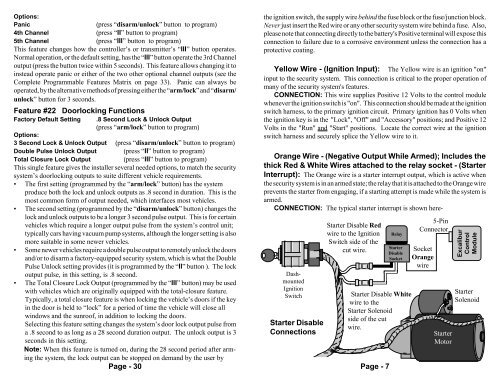
Orange Wire - (Negative Output While Armed); Includes the<br />
thick Red & White Wires attached to the relay socket - (Starter<br />
Interrupt): The Orange wire is a starter interrupt output, which is active when<br />
the security system is in an armed state; the relay that it is attached to the Orange wire<br />
prevents the starter from engaging, if a starting attempt is made while the system is<br />
armed.<br />
CONNECTION: The typical starter interrupt is shown here-<br />
Dashmounted<br />
Ignition<br />
Switch<br />
Starter Disable<br />
Connections<br />
Starter Disable Red<br />
wire to the Ignition<br />
Switch side of the<br />
cut wire.<br />
Page - 7<br />
Relay<br />
Starter<br />
Disable<br />
Socket<br />
Starter Disable White<br />
wire to the<br />
Starter Solenoid<br />
side of the cut<br />
wire.<br />
5-Pin<br />
Connector<br />
Socket<br />
Orange<br />
wire<br />
Starter<br />
Motor<br />
Excalibur<br />
Control<br />
Module<br />
Starter<br />
Solenoid