
You also want an ePaper? Increase the reach of your titles
YUMPU automatically turns print PDFs into web optimized ePapers that Google loves.
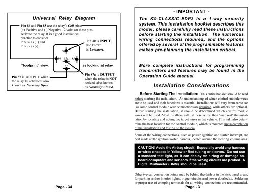
Universal Relay Diagram<br />
Pin 86 and Pin 85 are the relay’s Coil pins.<br />
(+) Positive and (-) Negative 12 volts on these pins<br />
activate the relay. It is a good installation<br />
practice to consider<br />
Pin 86 as (+) and<br />
Pin 85 as (-).<br />
30<br />
86 87a 85<br />
Pin 30 is INPUT,<br />
also known<br />
as Common.<br />
“footprint” view, 87 as looking at relay<br />
Pin 87 is OUTPUT when<br />
the relay IS activated, also<br />
known as Normally Open.<br />
Pin 87a is OUTPUT<br />
when the relay is NOT<br />
actived, also known<br />
as Normally Closed.<br />
- IMPORTANT -<br />
The K9-CLASSIC-EDP2 is a 1-way security<br />
system. This installation booklet describes this<br />
model; please <strong>car</strong>efully read these instructions<br />
before starting the installation. The numerous<br />
wiring connections required, and the options<br />
offered by several of the programmable features<br />
makes pre-planning the installation critical.<br />
More complete instructions for programming<br />
transmitters and features may be found in the<br />
Operation Guide manual.<br />
Installation Considerations<br />
Before Starting The Installation: This entire booklet should be read<br />
before starting the installation. An understanding of which control module wires<br />
are to be used and their functions is essential. Installations will vary from <strong>car</strong> to <strong>car</strong><br />
, as some control module wire connections are required, while others are optional.<br />
Before starting the installation, it should be determined which control module<br />
wires will be used. Most installers will list these wires, then "map out" the installation<br />
by locating and noting the target wires in the vehicle. This will also determine<br />
the best location for the control module, which is mounted upon completion<br />
of the installation and testing of the system.<br />
Some of the wiring connections, such as power, ignition and starter interrupt, are<br />
best made at the ignition switch harness, located around the steering column area.<br />
CAUTION! Avoid the Airbag circuit! Especially avoid any harness<br />
or wires encased in Yellow or Red tubing or sleeves. Do not use<br />
a standard test light, as it can deploy an airbag or damage onboard<br />
computers and sensors if the wrong circuits are probed. A<br />
Digital Multimeter (DMM) should be used.<br />
Page - 34<br />
Other typical connection points may be behind the dash or in the kick panel areas,<br />
for parking and/or interior lights, trigger circuits and power doorlocks. Soldering<br />
or proper use of crimping terminals for all wiring connections are recommended.<br />
Page - 3