
Create successful ePaper yourself
Turn your PDF publications into a flip-book with our unique Google optimized e-Paper software.
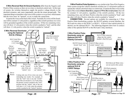
5 Wire Reversal Rest At Ground Systems differ from the Negative and<br />
Positive Pulse systems as there are no relays or doorlock control unit. In this type<br />
of system, the switches themselves supply the positive voltage directly to the<br />
doorlock actuators, and, more importantly, provide the return ground path. The<br />
important thing to remember is the wires in this system rest at ground, which means<br />
that the wires must be "opened", or cut, to make the connections.<br />
Examine the wires on the back of the switch. Normally five wires will be foundone<br />
will be constant 12 volts positive, regardless of the switch's position; two wires<br />
will be grounded regardless of the switch's position. Of the two remaining wires,<br />
one will show 12 volts positive when the switch is pushed to "lock", and the other<br />
will show 12 volts positive when the switch is pushed to "unlock".<br />
5 Wire Reversal Doorlocks<br />
using the Optional<br />
DLS & 2 Relays<br />
DLS Violet Wire<br />
to Constant<br />
(+)12 Volts<br />
Driver<br />
Doorlock<br />
Switch<br />
Unlock<br />
White wire<br />
to the "Switch"<br />
side of the<br />
cut “lock” wire<br />
Relay<br />
DLS<br />
Relay<br />
Cut both the “lock”<br />
Green wire<br />
to the "Motor"<br />
side of the<br />
cut “lock” wire<br />
DLS Red connector<br />
plugs into Control<br />
Unit<br />
Passenger<br />
Doorlock<br />
Switch<br />
Unlock<br />
3 Wire Positive Pulse Systems are very similar to the Three Wire Negative<br />
Pulse system except the vehicle's doorlock switches use 12 volt positive pulses to<br />
operate the vehicle's doorlock relays or control unit. Examine the three wires on the<br />
back of the switch; if more than three, suspect a 5 Wire Reversal system. One will<br />
be constant 12 volt positive, regardless of the switch's position. Of the two<br />
remaining wires, one will show Positive when the switch is pushed to "lock", and<br />
the other will show Positive when the switch is pushed to "unlock".<br />
CONNECTION: Several options are available for connecting to 3 Wire<br />
Positive Pulse doorlocking systems- the DLP-P3 polarity reversal interface, the<br />
DLS and two relays or the DLR-C or DLR-U. If driver's door unlock priority is<br />
desired, use the optional DLS-3. The following diagrams show how to connect<br />
either of the optional DLP-P3 or the DLS and 2 relay interfaces.<br />
3 Wire Positive Pulse<br />
Doorlocks using an<br />
Optional DLP-P3<br />
Polarity Converter<br />
DLP-P3 Green wire to<br />
Switch “lock” wire<br />
Doorlock Switch<br />
D/U+<br />
D/L+<br />
DLP-P3<br />
DLP-P3 Red connector<br />
plugs into the control<br />
module’s Red DLS port<br />
DLP-P3 Blue wire to<br />
switch “unlock” wire<br />
Vehicle's Doorlock<br />
Relay Control Unit<br />
Unlock<br />
Lock<br />
Door<br />
Motors<br />
Lock<br />
Driver<br />
Motors<br />
Brown wire<br />
to the "Switch"<br />
side of the cut<br />
“unlock” wire<br />
and “unlock” wires*<br />
Page - 20<br />
Blue wire<br />
to the "Motor"<br />
side of the<br />
cut “unlock” wire<br />
Cutting only one of two wires can cause<br />
misleading test results. For example, if<br />
only the “lock” wire is cut, the “switch”<br />
side of the cut will show (+)12 Volts when<br />
the primary switch is pushed to the "lock"<br />
position and the “motor” side of the cut<br />
will show (+)12 Volts when the primary<br />
switch is pushed to the "unlock" position.<br />
Passenger<br />
Motors<br />
Lock<br />
3 Wire Positive Pulse<br />
Doorlocks using an<br />
optional DLS &<br />
2 SPDT Relays<br />
DLS Violet Wire<br />
to Constant<br />
(+)12 Volts.<br />
DLS Green wire to<br />
Switch “lock” wire<br />
Doorlock Switch<br />
+12V<br />
Relay<br />
DLS<br />
Relay<br />
DLS Blue wire to<br />
Switch “unlock” wire<br />
Unlock<br />
Lock<br />
Page - 17<br />
DLS Red connector<br />
plugs into the control<br />
module’s Red port<br />
Door<br />
Motors<br />
Vehicle's Doorlock<br />
Relay Control Unit<br />
DLS Brown & White wires<br />
are not used in this system<br />
Text continues on Page 20