

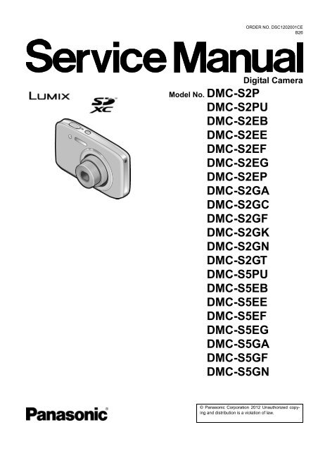
DMC-S2PU DMC-S2EB DMC-S2EE DMC-S2EF DMC ... - Panasonic
DMC-S2PU DMC-S2EB DMC-S2EE DMC-S2EF DMC ... - Panasonic
DMC-S2PU DMC-S2EB DMC-S2EE DMC-S2EF DMC ... - Panasonic

You also want an ePaper? Increase the reach of your titles
YUMPU automatically turns print PDFs into web optimized ePapers that Google loves.
ORDER NO. DSC1202001CE<br />
B26<br />
Digital Camera<br />
Model No. <strong>DMC</strong>-S2P<br />
<strong>DMC</strong>-<strong>S2PU</strong><br />
<strong>DMC</strong>-<strong>S2EB</strong><br />
<strong>DMC</strong>-<strong>S2EE</strong><br />
<strong>DMC</strong>-<strong>S2EF</strong><br />
<strong>DMC</strong>-S2EG<br />
<strong>DMC</strong>-S2EP<br />
<strong>DMC</strong>-S2GA<br />
<strong>DMC</strong>-S2GC<br />
<strong>DMC</strong>-S2GF<br />
<strong>DMC</strong>-S2GK<br />
<strong>DMC</strong>-S2GN<br />
<strong>DMC</strong>-S2GT<br />
<strong>DMC</strong>-S5PU<br />
<strong>DMC</strong>-S5EB<br />
<strong>DMC</strong>-S5EE<br />
<strong>DMC</strong>-S5EF<br />
<strong>DMC</strong>-S5EG<br />
<strong>DMC</strong>-S5GA<br />
<strong>DMC</strong>-S5GF<br />
<strong>DMC</strong>-S5GN<br />
© <strong>Panasonic</strong> Corporation 2012 Unauthorized copying<br />
and distribution is a violation of law.
Colour<br />
[<strong>DMC</strong>-S2]<br />
(K)...........Black Type<br />
(W)..........White Type (except P/EP)<br />
(P)...........Pink Type (except P/EP)<br />
(V)...........Violet Type (except EE/EP/GK)<br />
(R)...........Red Type (only EB)<br />
[<strong>DMC</strong>-S5]<br />
(K)...........Black Type<br />
(S)...........Silver Type (except EB/EE/EF)<br />
(R)...........Red Type (except EF)<br />
TABLE OF CONTENTS<br />
PAGE<br />
1 Safety Precautions -----------------------------------------------3<br />
1.1. General Guidelines ----------------------------------------3<br />
1.2. Leakage Current Cold Check ---------------------------3<br />
1.3. Leakage Current Hot Check (See Figure 1.)--------3<br />
1.4. How to Discharge the E.Capacitor on Flash<br />
P.C.B.----------------------------------------------------------4<br />
2Warning--------------------------------------------------------------5<br />
2.1. Prevention of Electrostatic Discharge (ESD)<br />
to Electrostatically Sensitive (ES) Devices ----------5<br />
2.2. How to Recycle the Lithium Ion Battery (U.S.<br />
Only)-----------------------------------------------------------5<br />
2.3. Caution for AC Cord(For EB/GC) ----------------------6<br />
2.4. How to Replace the Lithium Battery-------------------7<br />
3 Service Navigation------------------------------------------------8<br />
3.1. Introduction --------------------------------------------------8<br />
3.2. Important Notice (About minimum<br />
replacement part size: MAIN P.C.B. & LENS<br />
UNIT) ---------------------------------------------------------8<br />
3.3. General Description About Lead Free Solder<br />
(PbF) ----------------------------------------------------------9<br />
3.4. How to Define the Model Suffix (NTSC or PAL<br />
model)------------------------------------------------------- 10<br />
4 Specifications ---------------------------------------------------- 15<br />
5 Location of Controls and Components------------------ 16<br />
6 Service Mode ----------------------------------------------------- 18<br />
6.1. Error Code Memory Function ------------------------- 18<br />
7 Service Fixture & Tools --------------------------------------- 21<br />
7.1. Service Fixture and Tools ------------------------------ 21<br />
7.2. When Replacing the Main P.C.B. -------------------- 21<br />
8 Disassembly and Assembly Instructions--------------- 22<br />
8.1. Disassembly Flow Chart-------------------------------- 22<br />
8.2. P.C.B. Location ------------------------------------------- 22<br />
8.3. Disassembly Procedure -------------------------------- 23<br />
8.4. Removal of the CCD Unit ------------------------------ 29<br />
9 Measurements and Adjustments -------------------------- 30<br />
9.1. Introduction ------------------------------------------------ 30<br />
9.2. Before Disassembling the unit ------------------------ 30<br />
9.3. Details of Electrical Adjustment----------------------- 32<br />
9.4. After Adjustment------------------------------------------ 36<br />
PAGE<br />
10 Maintenance------------------------------------------------------ 37<br />
10.1. Cleaning Lens and LCD Panel ----------------------- 37<br />
11 Block Diagram --------------------------------------------------- 38<br />
11.1. Overall Block Diagram---------------------------------- 38<br />
11.2. Flash / Top Block Diagram ---------------------------- 39<br />
12 Wiring Connection Diagram -------------------------------- 40<br />
12.1. Interconnection Diagram------------------------------- 40<br />
2
1 Safety Precautions<br />
1.1. General Guidelines<br />
1. IMPORTANT SAFETY NOTICE<br />
There are special components used in this equipment<br />
which are important for safety. These parts are marked by<br />
in the Schematic Diagrams, Circuit Board Layout,<br />
Exploded Views and Replacement Parts List. It is essential<br />
that these critical parts should be replaced with manufacturer’s<br />
specified parts to prevent X-RADIATION,<br />
shock, fire, or other hazards. Do not modify the original<br />
design without permission of manufacturer.<br />
2. An Isolation Transformer should always be used during<br />
the servicing of AC Adaptor whose chassis is not isolated<br />
from the AC power line. Use a transformer of adequate<br />
power rating as this protects the technician from accidents<br />
resulting in personal injury from electrical shocks. It<br />
will also protect AC Adaptor from being damaged by accidental<br />
shorting that may occur during servicing.<br />
3. When servicing, observe the original lead dress. If a short<br />
circuit is found, replace all parts which have been overheated<br />
or damaged by the short circuit.<br />
4. After servicing, see to it that all the protective devices<br />
such as insulation barriers, insulation papers shields are<br />
properly installed.<br />
5. After servicing, make the following leakage current<br />
checks to prevent the customer from being exposed to<br />
shock hazards.<br />
1.2. Leakage Current Cold Check<br />
1. Unplug the AC cord and connect a jumper between the<br />
two prongs on the plug.<br />
2. Measure the resistance value, with an ohmmeter,<br />
between the jumpered AC plug and each exposed metallic<br />
cabinet part on the equipment such as screwheads,<br />
connectors, control shafts, etc. When the exposed metallic<br />
part has a return path to the chassis, the reading<br />
should be between 1 MΩ and 5.2 MΩ. When the exposed<br />
metal does not have a return path to the chassis, the<br />
reading must be infinity.<br />
1.3. Leakage Current Hot Check<br />
(See Figure 1.)<br />
1. Plug the AC cord directly into the AC outlet. Do not use<br />
an isolation transformer for this check.<br />
2. Connect a 1.5 kΩ, 10 W resistor, in parallel with a 0.15 μF<br />
capacitor, between each exposed metallic part on the set<br />
and a good earth ground, as shown in Figure 1.<br />
3. Use an AC voltmeter, with 1 kΩ/V or more sensitivity, to<br />
measure the potential across the resistor.<br />
4. Check each exposed metallic part, and measure the voltage<br />
at each point.<br />
5. Reverse the AC plug in the AC outlet and repeat each of<br />
the above measurements.<br />
6. The potential at any point should not exceed 0.75 V RMS.<br />
A leakage current tester (Simpson Model 229 or equivalent)<br />
may be used to make the hot checks, leakage current<br />
must not exceed 1/2 mA. In case a measurement is<br />
outside of the limits specified, there is a possibility of a<br />
shock hazard, and the equipment should be repaired and<br />
rechecked before it is returned to the customer.<br />
Figure. 1<br />
3
1.4. How to Discharge the E.Capacitor on Flash P.C.B.<br />
CAUTION:<br />
1. Be sure to discharge the E.capacitor on FLASH P.C.B..<br />
2. Be careful of the high voltage circuit on FLASH P.C.B. when servicing.<br />
[Discharging Procedure]<br />
1. Refer to the disassemble procedure and remove the necessary parts/unit.<br />
2. Install the insulation tube onto the lead part of resistor (ERG5SJ102:1kΩ /5W).<br />
(An equivalent type of resistor may be used.)<br />
3. Place a resistor between both terminals of E.capacitor on the FLASH P.C.B. for approx. 5 seconds.<br />
4. After discharging, confirm that the E.capacitor voltage is lower than 10V by using a voltmeter.<br />
Fig. F1<br />
4
2 Warning<br />
2.1. Prevention of Electrostatic Discharge (ESD) to Electrostatically<br />
Sensitive (ES) Devices<br />
Some semiconductor (solid state) devices can be damaged easily by static electricity. Such components commonly are called Electrostatically<br />
Sensitive (ES) Devices.<br />
The following techniques should be used to help reduce the incidence of component damage caused by electrostatic discharge<br />
(ESD).<br />
1. Immediately before handling any semiconductor component or semiconductor-equipped assembly, drain off any ESD on your<br />
body by touching a known earth ground. Alternatively, obtain and wear a commercially available discharging ESD wrist strap,<br />
which should be removed for potential shock reasons prior to applying power to the unit under test.<br />
2. After removing an electrical assembly equipped with ES devices, place the assembly on a conductive surface such as aluminum<br />
foil, to prevent electrostatic charge buildup or exposure of the assembly.<br />
3. Use only a grounded-tip soldering iron to solder or unsolder ES devices.<br />
4. Use only an antistatic solder removal device. Some solder removal devices not classified as "antistatic (ESD protected)" can<br />
generate electrical charge sufficient to damage ES devices.<br />
5. Do not use freon-propelled chemicals. These can generate electrical charges sufficient to damage ES devices.<br />
6. Do not remove a replacement ES device from its protective package until immediately before you are ready to install it. (Most<br />
replacement ES devices are packaged with leads electrically shorted together by conductive foam, aluminum foil or comparable<br />
conductive material).<br />
7. Immediately before removing the protective material from the leads of a replacement ES device, touch the protective material<br />
to the chassis or circuit assembly into which the device will be installed.<br />
CAUTION :<br />
Be sure no power is applied to the chassis or circuit, and observe all other safety precautions.<br />
8. Minimize bodily motions when handling unpackaged replacement ES devices. (Otherwise harmless motion such as the<br />
brushing together of your clothes fabric or the lifting of your foot from a carpeted floor can generate static electricity (ESD) sufficient<br />
to damage an ES device).<br />
2.2. How to Recycle the Lithium Ion Battery (U.S. Only)<br />
5
2.3. Caution for AC Cord<br />
(For EB/GC)<br />
2.3.1. Information for Your Safety<br />
IMPORTANT<br />
Your attention is drawn to the fact that recording of prerecorded<br />
tapes or discs or other published or broadcast<br />
material may infringe copyright laws.<br />
WARNING<br />
To reduce the risk of fire or shock hazard, do not expose<br />
this equipment to rain or moisture.<br />
CAUTION<br />
To reduce the risk of fire or shock hazard and annoying<br />
interference, use the recommended accessories only.<br />
FOR YOUR SAFETY<br />
DO NOT REMOVE THE OUTER COVER<br />
To prevent electric shock, do not remove the cover. No user<br />
serviceable parts inside. Refer servicing to qualified service<br />
personnel.<br />
2.3.2. Caution for AC Mains Lead<br />
For your safety, please read the following text carefully.<br />
This appliance is supplied with a moulded three-pin mains plug<br />
for your safety and convenience.<br />
A 5-ampere fuse is fitted in this plug.<br />
Should the fuse need to be replaced please ensure that the<br />
replacement fuse has a rating of 5 amperes and it is approved<br />
by ASTA or BSI to BS1362<br />
Check for the ASTA mark or the BSI mark on the body of the<br />
fuse.<br />
2.3.2.1. Important<br />
The wires in this mains lead are coloured in accordance with<br />
the following code:<br />
Blue<br />
Brown<br />
Neutral<br />
Live<br />
As the colours of the wires in the mains lead of this appliance<br />
may not correspond with the coloured markings identifying the<br />
terminals in your plug, proceed as follows:<br />
The wire which is coloured BLUE must be connected to the terminal<br />
in the plug which is marked with the letter N or coloured<br />
BLACK.<br />
The wire which is coloured BROWN must be connected to the<br />
terminal in the plug which is marked with the letter L or coloured<br />
RED.<br />
Under no circumstances should either of these wires be connected<br />
to the earth terminal of the three pin plug, marked with<br />
the letter E or the Earth Symbol.<br />
2.3.2.2. Before Use<br />
Remove the Connector Cover as follows.<br />
If the plug contains a removable fuse cover you must ensure<br />
that it is refitted when the fuse is replaced.<br />
If you lose the fuse cover, the plug must not be used until a<br />
replacement cover is obtained.<br />
A replacement fuse cover can be purchased from your local<br />
<strong>Panasonic</strong> Dealer.<br />
2.3.2.3. How to Replace the Fuse<br />
1. Remove the Fuse Cover with a screwdriver.<br />
If the fitted moulded plug is unsuitable for the socket outlet in<br />
your home then the fuse should be removed and the plug cut<br />
off and disposed of safety.<br />
There is a danger of severe electrical shock if the cut off plug is<br />
inserted into any 13-ampere socket.<br />
If a new plug is to be fitted please observe the wiring code as<br />
shown below.<br />
If in any doubt, please consult a qualified electrician.<br />
2. Replace the fuse and attach the Fuse cover.<br />
6
2.4. How to Replace the Lithium Battery<br />
2.4.1. Replacement Procedure<br />
1. Remove the TOP P.C.B.. (Refer to Disassembly Procedures.)<br />
2. Unsolder the each soldering point of electric lead terminal for Lithium battery (Ref. No. “B6301” at foil side of TOP P.C.B.) and<br />
remove the Lithium battery together with electric lead terminal. Then replace it into new one.<br />
NOTE:<br />
The Type No. ML421 includes electric lead terminals.<br />
NOTE:<br />
This Lithium battery is a critical component.<br />
(Type No.: ML421 Manufactured by Energy Company, <strong>Panasonic</strong> Corporation.)<br />
It must never be subjected to excessive heat or discharge.<br />
It must therefore only be fitted in requirement designed specifically for its use.<br />
Replacement batteries must be of same type and manufacture.<br />
They must be fitted in the same manner and location as the original battery, with the correct polarity contacts observed.<br />
Do not attempt to re-charge the old battery or re-use it for any other purpose.<br />
It should be disposed of in waste products destined for burial rather than incineration.<br />
NOTE:<br />
Above caution is applicable for a battery pack which is for <strong>DMC</strong>-S2/S5 series, as well.<br />
7
3 Service Navigation<br />
3.1. Introduction<br />
This service manual contains technical information, which allow service personnel’s to understand and service this model.<br />
Please place orders using the parts list and not the drawing reference numbers.<br />
If the circuit is changed or modified, the information will be followed by service manual to be controlled with original service manual.<br />
3.2. Important Notice (About minimum replacement part size: MAIN P.C.B. &<br />
LENS UNIT)<br />
3.2.1. MAIN P.C.B.:<br />
1. The MAIN P.C.B. is handled as the smallest replacement part for this unit.<br />
Therefore if any component on the MAIN P.C.B. is/are defective, replace whole MAIN P.C.B. as a unit.<br />
3.2.2. LENS UNIT:<br />
1. The minimum replacement part size of the Lens part is as shown below.<br />
When servicing, replace the following numbered replacement part size as the smallest size.<br />
3.2.3. About Flexible Cable and Connector<br />
Do not touch carelessly so that the foreign body should not adhere to the terminal part of flexible cable and connector.<br />
Wipe off with a clean cloth and the cotton bud, etc. when the terminal part is dirty.<br />
8
3.3. General Description About Lead Free Solder (PbF)<br />
The lead free solder has been used in the mounting process of all electrical components on the printed circuit boards used for this<br />
equipment in considering the globally environmental conservation.<br />
The normal solder is the alloy of tin (Sn) and lead (Pb). On the other hand, the lead free solder is the alloy mainly consists of tin<br />
(Sn), silver (Ag) and Copper (Cu), and the melting point of the lead free solder is higher approx.30°C (86°F) more than that of the<br />
normal solder.<br />
Distinction of P.C.B. Lead Free Solder being used<br />
Service caution for repair work using Lead Free Solder (PbF)<br />
• The lead free solder has to be used when repairing the equipment for which the lead free solder is used.<br />
(Definition: The letter of “PbF” is printed on the P.C.B. using the lead free solder.)<br />
• To put lead free solder, it should be well molten and mixed with the original lead free solder.<br />
• Remove the remaining lead free solder on the P.C.B. cleanly for soldering of the new IC.<br />
• Since the melting point of the lead free solder is higher than that of the normal lead solder, it takes the longer time to melt the<br />
lead free solder.<br />
• Use the soldering iron (more than 70W) equipped with the temperature control after setting the temperature at 350±30°C<br />
(662±86°F).<br />
Recommended Lead Free Solder (Service Parts Route.)<br />
• The following 3 types of lead free solder are available through the service parts route.<br />
RFKZ03D01KS-----------(0.3mm 100g Reel)<br />
RFKZ06D01KS-----------(0.6mm 100g Reel)<br />
RFKZ10D01KS-----------(1.0mm 100g Reel)<br />
Note<br />
* Ingredient: tin (Sn) 96.5%, silver (Ag) 3.0%, Copper (Cu) 0.5%, Cobalt (Co) / Germanium (Ge) 0.1 to 0.3%<br />
9
3.4. How to Define the Model Suffix (NTSC or PAL model)<br />
There are eight kinds of <strong>DMC</strong>-S2 and <strong>DMC</strong>-S5, regardless of the colours.<br />
• a) <strong>DMC</strong>-S2 (Japan domestic model)<br />
• b) <strong>DMC</strong>-S2P<br />
• c) <strong>DMC</strong>-<strong>S2EB</strong>/EF/EG/EP, <strong>DMC</strong>-S5EB/EF/EG<br />
• d) <strong>DMC</strong>-<strong>S2EE</strong>,<strong>DMC</strong>-S5EE<br />
• e) <strong>DMC</strong>-S2GT<br />
• f) <strong>DMC</strong>-S2GK<br />
• g) <strong>DMC</strong>-S2GN,<strong>DMC</strong>-S5GN<br />
• h) <strong>DMC</strong>-<strong>S2PU</strong>/GA/GC/GF, <strong>DMC</strong>-S5PU/GA/GF<br />
What is the difference is that the “INITIAL SETTINGS” data which is stored in Flash-ROM mounted on MAIN P.C.B..<br />
3.4.1. Defining methods:<br />
To define the model suffix to be serviced, refer to the nameplate which is putted on the bottom side of the Unit.<br />
NOTE:<br />
After replacing the MAIN P.C.B., be sure to achieve adjustment.<br />
The service software is available at “TSN Website”. To download, click on “Support Information from NWBG/VDBG-AVC”.<br />
10
3.4.2. INITIAL SETTINGS:<br />
After replacing the MAIN P.C.B., make sure to perform the initial settings after achieving the adjustment by ordering the following<br />
procedure in accordance with model suffix of the unit.<br />
1. IMPORTANT NOTICE:<br />
Before proceeding Initial settings, make sure to read the following CAUTIONS.<br />
2. PROCEDURES:<br />
• Precautions: Read the above "CAUTION 1" and "CAUTION 2", carefully.<br />
• Preparation:<br />
- Attach the Battery or AC Adaptor with a DC coupler to the unit.<br />
(Since this unit has built-in memory, it can be performed without inserting SD memory card.)<br />
1. Turn the Power on.<br />
2. Press the [ MODE ] button, and select the [ NORMAL PICTURE ] mode by Cursor buttons, then press the [ MENU/SET ]<br />
button.<br />
3. Turn the Power off.<br />
(If the unit is other than [ NORMAL PICTURE ] mode, it does not display the initial settings menu.)<br />
• Step 1. The temporary cancellation of “INITIAL SETTINGS”:<br />
While pressing “[ W ] side of Zoom button” and “[ UP ] of Cursor button” simultaneously, turn the Power on.<br />
• Step 2. The cancellation of “INITIAL SETTINGS”:<br />
Press the [ PLAYBACK ] button.<br />
While pressing the “[ UP ] of Cursor button”, press and hold the "[ W ] side of the Zoom button". Release only the "[ UP ] of Cursor<br />
button" once then press the "[ UP ] of Cursor button" again.<br />
Release the "[ W ]" and "[ UP ]" buttons, then turn the Power off.<br />
The LCD displays the " ! " mark before the unit powers down.<br />
• Step 3. Turn the Power on:<br />
Turn the Power on.<br />
• Step 4. Display the INITIAL SETTING:<br />
While pressing [ MENU/SET ] button and “[ RIGHT ] of Cursor button” simultaneously, turn the Power off.<br />
The “INITIAL SETTINGS” menu is displayed.<br />
There are two kinds of “INITIAL SETTINGS” menu form as follows:<br />
11
[CASE 1. After replacing MAIN P.C.B.]<br />
When MAIN P.C.B. has just been replaced, all of the model suffix is displayed as follows. (Five pages in total)<br />
[CASE 2. Other than “After replacing MAIN P.C.B.”]<br />
12
• Step 5. Choose the model suffix in “INITIAL SETTINGS”: (Refer to “CAUTION 1”)<br />
[Caution: After replacing MAIN P.C.B.]<br />
The model suffix can been chosen, JUST ONE TIME.<br />
Once one of the model suffix have been chosen, the model suffix lists will not be displayed, thus, it can not be changed.<br />
Therefore, select the area carefully.<br />
Select the area with pressing “[ UP ] / [ DOWN ] of Cursor buttons”.<br />
• Step 6. Set the model suffix in “INITIAL SETTINGS”:<br />
Press the “[ RIGHT ] of Cursor buttons”.<br />
The only set area is displayed, and then press the “[ RIGHT ] of Cursor buttons” after confirmation.<br />
(The unit is powered off automatically.)<br />
13
• Step 7. CONFIRMATION:<br />
Confirm the display of “PLEASE SET THE CLOCK” in concerned language when the unit is turned on again.<br />
When the unit is connected to PC with USB cable, it is detected as removable media.<br />
(When the “GT” or “GK” model suffix is selected, the display shows “PLEASE SET THE CLOCK” in Chinese.)<br />
1) As for your reference, major default setting condition is as shown in the following table.<br />
• Default setting (After “INITIAL SETTINGS”)<br />
MODEL VIDEO OUTPUT LANGUAGE DATE REMARKS<br />
a) <strong>DMC</strong>-S2(Japan domestic model) NTSC Japanese Year/Month/Date<br />
b) <strong>DMC</strong>-S2P NTSC English Month/Date/Year<br />
c) <strong>DMC</strong>-<strong>S2PU</strong>/S5PU NTSC Spanish Month/Date/Year<br />
d) <strong>DMC</strong>-S2EG/S5EG PAL English Date/Month/Year<br />
e) <strong>DMC</strong>-S2EP PAL English Date/Month/Year<br />
f) <strong>DMC</strong>-<strong>S2EF</strong>/S5EF PAL French Date/Month/Year<br />
g) <strong>DMC</strong>-<strong>S2EB</strong>/S5EB PAL English Date/Month/Year<br />
h) <strong>DMC</strong>-<strong>S2EE</strong>/S5EE PAL Russian Date/Month/Year<br />
i) <strong>DMC</strong>-S2GC PAL English Date/Month/Year<br />
j) <strong>DMC</strong>-S2GF/S5GF PAL English Date/Month/Year<br />
k) <strong>DMC</strong>-S2GA/S5GA PAL English Date/Month/Year<br />
l) <strong>DMC</strong>-S2GT NTSC Chinese (traditional) Year/Month/Date<br />
m) <strong>DMC</strong>-S2GK PAL Chinese (simplified) Year/Month/Date<br />
n) <strong>DMC</strong>-S2GN/S5GN PAL English Date/Month/Year<br />
14
4 Specifications<br />
15
5 Location of Controls and Components<br />
1 2 3 4 5 6 7 8<br />
20<br />
19<br />
18 17<br />
16<br />
15<br />
14<br />
9<br />
10<br />
11<br />
12<br />
13<br />
1 Self-timer indicator/AF Assist Lamp<br />
2 Flash<br />
3 Lens<br />
4 Lens barrel<br />
5 LCD monitor<br />
6 Power button<br />
7 Microphone<br />
8 Shutter button<br />
9 Zoom button<br />
10 [MODE] button<br />
11 Hand strap eyelet<br />
12 [AV OUT/DIGITAL] socket<br />
13 [ / ] (Delete/Return) button<br />
14 [MENU/SET] button<br />
15 Playback button<br />
16 Cursor button<br />
17 Tripod receptacle<br />
18 Speaker<br />
19 DC coupler cover<br />
20 Card/Battery door<br />
We recommend using<br />
the supplied hand strap<br />
to avoid dropping the<br />
camera.<br />
[MENU/SET]<br />
(menu display/set)<br />
Left cursor button ( )<br />
Self-timer<br />
Cursor button<br />
Up cursor button ( )<br />
Exposure Compensation<br />
Right cursor button ( )<br />
Flash<br />
Down cursor button ( )<br />
Changing information display<br />
16
Selecting the Recording Mode<br />
Press the Power button<br />
Press [MODE] button<br />
Use cursor button to select the<br />
recording mode and press<br />
[MENU/SET]<br />
Recording mode<br />
[Intelligent Auto] Mode<br />
Take pictures with automatic settings.<br />
[Normal Picture] Mode<br />
Take pictures with your own settings.<br />
[Scene Mode]<br />
Take pictures according to scene.<br />
[Motion Picture] Mode<br />
Take motion pictures.<br />
17
6 Service Mode<br />
6.1. Error Code Memory Function<br />
1. General description<br />
This unit is equipped with history of error code memory function, and can be memorized 16 error codes in sequence from the<br />
latest. When the error is occurred more than 16, the oldest error is overwritten in sequence.<br />
The error code is not memorized when the power supply is shut down forcibly (i.e.,when the unit is powered on by the battery,<br />
the battery is pulled out) The error code is memorized to FLASH-ROM when the unit has just before powered off.<br />
2. How to display<br />
The error code can be displayed by ordering the following procedure:<br />
• Preparation:<br />
- Attach the Battery or AC Adaptor with a DC coupler to the unit.<br />
(Since this unit has built-in memory, it can be performed without inserting SD memory card.)<br />
1. Turn the Power on.<br />
2. Press the [ MODE ] button, and select the [ NORMAL PICTURE ] mode by Cursor buttons, then press the [ MENU/SET ]<br />
button.<br />
• Step 1. The temporary cancellation of “INITIAL SETTINGS”:<br />
While pressing “[ W ] side of Zoom button” and “[ UP ] of Cursor button” simultaneously, turn the power on.<br />
• Step 2. Execute the error code display mode:<br />
While pressing the "[ W ] side of the Zoom button", press the "[ LEFT ] of Cursor button" and the "[ MENU/SET ] button simultaneously.<br />
Every time when performing above operation, the display is changed as shown below.<br />
Normal display → Error code display → Operation history display →Normal display →.....<br />
Example of Error Code Display<br />
18
• 3. Error Code List<br />
The error code consists of 8 bits data and it shows the following information.<br />
19
Important notice about "Error Code List"<br />
1) About "*" indication:<br />
The third digit from the left is different as follows.<br />
- In case of 0 (example: 18001000)<br />
When the third digit from the left shows "0", this error occurred under the condition of INITIAL SETTINGS has been<br />
completed.<br />
It means that this error is occurred basically at user side.<br />
- In case of 8 (example: 18801000)<br />
When the third digit from the left shows "8", this error occurred under the condition of INITIAL SETTINGS has been<br />
released.<br />
(Example; Factory assembling-line before unit shipment, Service mode etc.)<br />
It means that this error is occurred at service side.<br />
2) About "?" indication: ("18*0 0?01" to "18*0 0?60"):<br />
The third digit from the right shows one of the hexadecimal ("0" to "F") character.<br />
• 4. How to exit from Error Code display mode:<br />
Simply, turn the power off. (Since Error code display mode is executed under the condition of temporary cancellation of "INI-<br />
TIAL SETTINGS", it wake up with normal condition when turn off the power.)<br />
NOTE:<br />
The error code can not be initialized.<br />
20
7 Service Fixture & Tools<br />
7.1. Service Fixture and Tools<br />
The following Service Fixture and tools are used for checking and servicing this unit.<br />
7.2. When Replacing the Main P.C.B.<br />
After replacing the MAIN P.C.B., be sure to achieve adjustment.<br />
The service software is available at “TSN Website”. To download, click on “Support Information from NWBG/VDBG-AVC”.<br />
21
8 Disassembly and Assembly Instructions<br />
8.1. Disassembly Flow Chart<br />
This is a disassembling chart.<br />
When assembling, perform this chart conversely.<br />
8.2. P.C.B. Location<br />
22
8.3. Disassembly Procedure 8.3.1. Removal of the Rear Case Unit<br />
No. Item Fig Removal<br />
1 Rear Case Unit (Fig. D1) Card<br />
Battery<br />
3 Screws (A)<br />
1 Screw (B)<br />
(Fig. D2) 5 Locking tabs<br />
Rear Case Unit<br />
2 Center Ornament Unit (Fig. D3) 4 Locking tabs<br />
Center Ornament Unit<br />
3 Rear Operation Unit (Fig. D4) 1 Screw (C)<br />
1 Convex<br />
Connector (A)<br />
Rear Operation Unit<br />
4 LCD Unit (Fig. D5) 2 Locking tabs<br />
Connector (B)<br />
LCD Unit<br />
5 Lens Unit (W/CCD) (Fig. D6) 1 Screw (D)<br />
1 Screw (E)<br />
3 Locking tabs<br />
Frame Plate<br />
Connector (C)<br />
DPR Sheet A<br />
Trigger Cover<br />
(Fig. D7) Connector (D)<br />
Connector (E)<br />
Lens Unit (W/CCD)<br />
6 Speaker<br />
(Fig. D8) Discharge the E.Capacitor<br />
Flash P.C.B.<br />
(Fig. D9) FP8001 (Flex)<br />
1 Screw (F)<br />
Tripod Frame<br />
Solder (2 points)<br />
Speaker<br />
(Fig. D10) Solder (3 points)<br />
Flash P.C.B.<br />
7 Front Case Unit (Fig. D11) 4 Locking tabs<br />
Front Case Unit<br />
8 Main P.C.B. (Fig. D12) Terminal Cover<br />
1 Screw (G)<br />
Solder (14 points)<br />
1 Convex<br />
Main P.C.B.<br />
9 Flash Unit (Fig. D13) 2 Locking tabs<br />
Flash Unit<br />
10 Top P.C.B. (Fig. D14) 1 Screw (H)<br />
Sheet<br />
2 Convexes<br />
1 Hooking part<br />
Top P.C.B.<br />
10 Battery Door Unit (Fig. D15) Battery Door Shaft<br />
Battery Door Unit<br />
(Fig. D1)<br />
23
8.3.3. Removal of the Rear Operation Unit<br />
(Fig. D2)<br />
8.3.2. Removal of the Center Ornament<br />
Unit<br />
(Fig. D4)<br />
(Fig. D3)<br />
24
8.3.4. Removal of the LCD Unit<br />
8.3.5. Removal of the Lens Unit (W/CCD)<br />
(Fig. D5)<br />
(Fig. D6)<br />
25
(Fig. D7)<br />
8.3.6. Removal of the Speaker and Flash<br />
P.C.B.<br />
(Fig. D8)<br />
(Fig. D9)<br />
26
8.3.7. Removal of the Front Case Unit<br />
(Fig. D11)<br />
(Fig. D10)<br />
27
8.3.8. Removal of the Main P.C.B.<br />
8.3.9. Removal of the Flash Unit<br />
(Fig. D13)<br />
8.3.10. Removal of the Top P.C.B.<br />
(Fig. D12)<br />
[WHEN ASSEMBLING]<br />
CAUTION: Before soldering the Terminal A (Connecting<br />
part of Main P.C.B. and Top P.C.B.)<br />
Before soldering the Terminal A, make sure to tighten the<br />
"Screw (D)" first in order to eliminate the gap between Main<br />
P.C.B. and Battery Case Unit. Otherwise, soldered terminal A<br />
part may be damaged after assembling.<br />
NOTE:<br />
Since the screw (D) is for fixing the frame plate, the screw<br />
(D) has to be removed once, after soldering.<br />
(Fig. D14)<br />
28
8.3.11. Removal of the Battery Door Unit<br />
8.4. Removal of the CCD Unit<br />
To prevent the CCD unit from catching the dust and dirt, do not<br />
remove the CCD unit except for replacing.<br />
(Fig. D15)<br />
NOTE: (When Installing)<br />
Make sure to confirm the following points when installing:<br />
• The Screw is tightened enough.<br />
• Installing conditions are fine. (No distortion, no abnormalspace.)<br />
• No dust and/or dirt on Lens surfaces.<br />
• LCD image is fine. (No dust and dirt on it, and no gradient<br />
images.)<br />
(Fig. D16)<br />
29
9 Measurements and Adjustments<br />
9.1. Introduction<br />
When servicing this unit, make sure to perform the adjustments necessary based on the part(s) replaced.<br />
Before disassembling the unit, it is recommended to back up the camera data stored in flash-rom as a data file.<br />
IMPORTANT NOTICE (After replacing the MAIN P.C.B.)<br />
After replacing the MAIN P.C.B., it is necessary to use the “DIAS” software to allow the release of adjustment flag(s).<br />
The Adjustment software “DIAS” is available at “TSN Website”. To download, click on “Support Information from NWBG/VDBG-<br />
AVC”.<br />
*DIAS (DSC Integrated Assist Software)<br />
9.2. Before Disassembling the unit<br />
9.2.1. Initial Setting Release<br />
The cameras specification are initially set in accordance with model suffix (such as EB, EG, GK, GC, and so on.).<br />
Unless the initial setting is not released, an automatic alignment software in the camera is not able to be executed when the alignment<br />
is carried out.<br />
Note:<br />
The initial setting should be again done after completing the alignment. Otherwise, the camera may not work properly.<br />
Therefore as a warning, the camera display a warning symbol “ ! ” on the LCD monitor every time the camera is turned off.<br />
Refer to the procedure described in “3.4.2 INITIAL SETTINGS” for details.<br />
[ How to Release the camera initial setting ]<br />
Preparation:<br />
• Attach the Battery or AC Adaptor with a DC coupler to the unit.<br />
(Since this unit has built-in memory, it can be performed without inserting SD memory card.)<br />
1. Turn the Power on.<br />
2. Press the [ MODE ] button, and select the [ NORMAL PICTURE ] mode by Cursor buttons, then press the [ MENU/SET ] button.<br />
3. Turn the Power off.<br />
(If the unit is other than [ NORMAL PICTURE ] mode, it does not display the initial settings menu.)<br />
Step 1. Temporary cancellation of “INITIAL SETTINGS”:<br />
While pressing “[ W ] side of Zoom button” and “[ UP ] of Cursor button” simultaneously, turn the Power on.<br />
Step 2. Cancellation of “INITIAL SETTINGS”:<br />
Press the [ PLAYBACK ] button.<br />
While pressing the "[ UP ] of Cursor button", press and hold the "[ W ] side of the Zoom button". Release only the "[ UP ] of Cursor<br />
button" once then press the "[ UP ] of Cursor button" again.<br />
Release the "[ W ]" and "[ UP ]" buttons, then turn the Power off.<br />
The LCD displays the " ! " mark before the unit powers down.<br />
30
9.2.2. Flash-Rom Data Backup<br />
When trouble occurs, it is recommended to backup the Flash-rom data before disassembling the unit.<br />
There are two kinds of Flash-rom data backup methods:<br />
[ ROM_BACKUP (Method of Non-PC backup) ]<br />
1. Insert the SD-card into the camera.<br />
2. Set the camera to “Temporary cancellation of the initial settings”.<br />
3. Select the “SETUP” menu.<br />
From the “SETUP” menu, select “ROM BACKUP”.<br />
NOTE:<br />
This item is not listed on the customer's “SETUP” menu.<br />
4. When this “ROM_BACKUP” item is selected, the following submenus are displayed.<br />
[ DSC Integrated Assist Software (Method of Using PC) ]<br />
Same as TATSUJIN software for previous models.<br />
9.2.3. Light Box<br />
If using VFK1164TDVLB Light Box, remove the lens connection<br />
ring by loosing three hexagon screws.<br />
31
9.3. Details of Electrical Adjustment<br />
9.3.1. How to execute the Electrical Adjustment<br />
It is not necessary to connect the camera to a PC to perform adjustments.<br />
“Flag reset operation” and “Initial setting operation” are required when carrying out the alignment, follow the procedure below.<br />
9.3.1.1. Startup Electrical Adjustment mode<br />
1. Release the initial settings.<br />
2. Insert a recordable SD card.<br />
(Without a SD card, the automatic adjustment can not<br />
executed.)<br />
3. Procedure to set the camera into adjustment mode:<br />
a. Turn the Power on.<br />
b. Press the [ MODE ] button, and select the [ NORMAL<br />
PICTURE ] mode by Cursor buttons, then press the<br />
[ MENU/SET ] button.<br />
c. Turn the Power off.<br />
d. Turn the Power on pressing “[ W ] side of Zoom button”<br />
and [ MODE ] button simultaneously.<br />
LCD monitor displays “SERVICE MODE”.(Refer to<br />
Fig. 3-1)<br />
9.3.1.2. Status Adjustment Flag Setting<br />
Reset (Not yet adjusted) the status flag condition.<br />
1. After pressing the “[ W ] side of Zoom button”, the LCD<br />
monitor displays the Flag status screen (Refer to Fig.3-2)<br />
2. Select item by pressing the Cursor buttons. (Gray cursor<br />
is moved accordingly.)<br />
3. Press the [ Delete/Return ] button.<br />
NOTE:<br />
The selected item's flag has been changed from<br />
“F (green)” to “0 (yellow)”.<br />
*Flag conditions:<br />
F (green)<br />
means that the alignment has been completed and the<br />
status flag condition is set. In this case, the flag condition<br />
should be reset, if you try to carry out the automatic alignment.<br />
0 (yellow)<br />
means that the alignment has been not “completed” and<br />
the status flag condition is “reset”. In this case, automatic<br />
alignment is available.<br />
• In case of setting the status flag into set condition again without completion of the alignment, the status flag should be SET by<br />
using PC, or UNDO by using ROM BACKUP function.<br />
32
9.3.1.3. Execute Adjustment<br />
(In case of “OIS Adjustment”)<br />
1. Perform step “9.3.1.1.” to “9.3.1.2.”, to reset the OIS flag<br />
status “F” (Set) to “0” (Reset)<br />
2. Press “[ W ] side of the zoom button” after Flag reset.<br />
OIS Adjustment screen is displayed on the LCD panel.<br />
(Refer to Fig.3-3)<br />
3. Press the [ Shutter ] button. The adjustment will start<br />
automatically.<br />
4. When the adjustment is completed successfully, adjustment<br />
report menu appears with Green OK on the LCD<br />
monitor. (Refer to Fig.3-4)<br />
9.3.1.4. Attention point during Adjustment<br />
1. Step “9.3.1.3.” procedure shows OIS adjustment as an<br />
example. To perform the adjustment, refer to the “9.3.2.<br />
Adjustment Specifications” table which shows key point<br />
for each adjustment.<br />
2. Do not move the light box, the camera or the chart while<br />
adjusting. If one of these is moved accidentally, start the<br />
adjustment again.<br />
3. Do not press any buttons/keys until the default menu<br />
(Fig.3-5) is displayed on the LCD monitor. Otherwise,<br />
adjustment data may not be stored properly.<br />
4. If the adjustment is interrupted accidentally, the alignment<br />
data may not be properly saved in the Flash-rom.<br />
9.3.1.5. Finalizing the Adjustment<br />
1. Several adjustment flags can be reset (“F” into “0”) at the same time. In this case, when the adjustment has been completed,<br />
the screen will change showing the adjustment for the next item until all reset items are completed.<br />
Also, when the shutter button is pressed, the screen jump to the next adjustment item.<br />
2. To cancel the adjustment mode while in the process of performing the adjustment, follow this procedures.<br />
(1) Press “[ RIGHT ] of cursor button”.<br />
NOTE:<br />
• If adjustment is cancelled with above procedure, adjustment is not completed. Make sure to adjust it later.<br />
• Adjustment software “DIAS” is able to control the status of the adjustment flags.<br />
33
9.3.2. Adjustment Specifications<br />
The following matrix table shows the relation between the replaced part and the Necessary Adjustment.<br />
When a part is replaced, make sure to perform the necessary adjustment(s) in the order indicated.<br />
The table below shows all the information necessary to perform each adjustment.<br />
34
9.4. After Adjustment<br />
9.4.1. Initial Setting<br />
Since the initial setting has been released to execute the built-in adjustment software, it should be set up again before shipping the<br />
camera to the customer.<br />
Refer to the procedure described in “3.4.2. INITIAL SETTINGS” for details.<br />
[ IMPORTANT ]<br />
1. The initial setting should be done again after completing the alignment. Otherwise, the camera will not work properly.<br />
Therefore as a warning, the camera display a warning symbol “ ! ” on the LCD monitor every time the camera is turned off.<br />
2. Confirm that status of all adjustment flag show “F”. Even if one of the adjustment flag shows “0”, initial setting programmed is<br />
never executed.<br />
36
10 Maintenance<br />
10.1. Cleaning Lens and LCD Panel<br />
Do not touch the surface of lens and LCD Panel with your hand.<br />
When cleaning the lens, use air-Blower to blow off the dust.<br />
When cleaning the LCD Panel, dampen the lens cleaning paper with lens cleaner, and the gently wipe the its surface.<br />
Note:<br />
The Lens Cleaning KIT ; VFK1900BK (Only supplied as 10 set/Box) is available as Service Aid.<br />
37
11 Block Diagram<br />
11.1. Overall Block Diagram<br />
OVERALL BLOCK DIAGRAM<br />
(28mm ~ 112mm)<br />
CCD<br />
1/2.33"<br />
14.1 MEGA PIX (<strong>DMC</strong>-S2)<br />
16.1 MEGA PIX (<strong>DMC</strong>-S5)<br />
CCD SIGNAL<br />
PROCESSOR<br />
CDS, AGC,<br />
A/D, TG,<br />
CCD DRIVER<br />
(24MHz)<br />
MAIN P.C.B.<br />
ZOOM<br />
OIS UNIT<br />
IRIS<br />
SHUTTER<br />
FOCUS<br />
SD<br />
CARD<br />
REGULATOR<br />
MICROPHONE<br />
SYSTEM IC<br />
MOTOR DRIVE,<br />
OIS DRIVE&<br />
PRE PROCESS<br />
SYSTEM IC<br />
MICROPHONE AMP<br />
SPEAKER CONTROL<br />
VIDEO OUT<br />
SPEAKER<br />
GYRO<br />
SENSOR & AMP<br />
AV OUT / DIGITAL<br />
TERMINAL<br />
FLASH<br />
IC8100<br />
IGBT DRIVER<br />
REAR OPERATION UNIT<br />
VENUS ENGINE<br />
CAMERA PROCESS<br />
J-PEG COMP/EX PANDS<br />
MEDIA I/F<br />
USB I/F<br />
MAIN MICROPROCESSOR<br />
OIS CONTROL<br />
LENS DRIVE<br />
LCD DRIVE<br />
COLOR LCD<br />
PANEL<br />
2.7" PANEL<br />
230k dots<br />
SYSTEM IC<br />
(32.768kHz)<br />
REGULATOR<br />
SDRAM/512Mbit<br />
NAND FLASH ROM/1Gbit<br />
TOP OPERATION UNIT<br />
POWER<br />
(POWER SUPPLY)<br />
BATTERY<br />
<strong>DMC</strong>-S2/S5 OVERALL BLOCK DIAGRAM<br />
38
11.2. Flash / Top Block Diagram<br />
FLASH BLOCK DIAGRAM<br />
FLASH P.C.B.<br />
TL8003<br />
(UNREG+)<br />
FP8001<br />
1-3<br />
F8001<br />
2<br />
T8001<br />
3<br />
LAMP(+)<br />
(D GND)<br />
FP8001<br />
5-7<br />
CL8011<br />
1<br />
4<br />
C8003<br />
(For Flash<br />
Charge)<br />
CL8031<br />
TRG FIRST<br />
TL8007<br />
SAFETY GND<br />
IC8100<br />
(IGBT DRIVER)<br />
TRG SECOND<br />
TL8001<br />
3<br />
1<br />
FLASH<br />
To MAIN P.C.B.<br />
(A GND)<br />
FP8001<br />
9<br />
CL8010<br />
CL8006<br />
10 SW<br />
9 TEST<br />
8 CS<br />
7 FB<br />
GND 1<br />
DRV OUT 2<br />
VDD 3<br />
DRVIN 4<br />
CL8005<br />
2<br />
TRG G<br />
CL8032<br />
TL8002<br />
LAMP(-)<br />
(STB CHG DET)<br />
(STB CHG OUT)<br />
FP8001<br />
12<br />
FP8001<br />
10<br />
CL8004<br />
6 STAT<br />
CHARGE 5<br />
Q8001<br />
5<br />
4<br />
6<br />
7<br />
8<br />
(FLASH TRG)<br />
FP8001<br />
8<br />
CL8008<br />
3<br />
2<br />
1<br />
(IGBT VCC)<br />
(SP POS)<br />
(SP NEG)<br />
FP8001<br />
11<br />
FP8001<br />
14<br />
FP8001<br />
13<br />
RL8051<br />
RL8052<br />
SPEAKER<br />
TOP BLOCK DIAGRAM<br />
TOP P.C.B.<br />
(D GND)<br />
RL6301<br />
(D GND)<br />
RL6311<br />
(SHUTTER 0)<br />
(SHUTTER 1)<br />
RL6303<br />
RL6302<br />
S6301<br />
HALF<br />
SHUTTER SW<br />
2<br />
5<br />
1<br />
FULL<br />
4<br />
3<br />
D6301<br />
6<br />
To MAIN P.C.B.<br />
(CATHODE)<br />
(AF3R4V)<br />
RL6304<br />
RL6305<br />
AF ASSIST LED<br />
S6302<br />
POWER SW<br />
(POWER ON L)<br />
RL6310<br />
1 2<br />
(CLOCK)<br />
RL6307<br />
B6301<br />
Timer<br />
Back UP<br />
BATTERY<br />
3 4<br />
(MIC IN)<br />
RL6308<br />
M6301<br />
MICROPHONE<br />
(MIC GND)<br />
RL6309<br />
<strong>DMC</strong>-S2/S5 FLASH AND TOP BLOCK DIAGRAM<br />
39
12 Wiring Connection Diagram<br />
12.1. Interconnection Diagram<br />
TOP P.C.B.<br />
(FOIL SIDE)<br />
: (COMPONENT SIDE)<br />
M6301<br />
MICROPHONE UNIT<br />
RL6312<br />
RL6301<br />
RL6302<br />
RL6303<br />
RL6304<br />
RL6305<br />
RL6306<br />
RL6307<br />
RL6308<br />
RL6309<br />
RL6310<br />
RL6311<br />
RL6312<br />
RL6301<br />
RL6302<br />
RL6303<br />
RL6304<br />
RL6305<br />
RL6306<br />
RL6307<br />
RL6308<br />
RL6309<br />
RL6310<br />
RL6311<br />
N.C.<br />
D GND<br />
SHUTTER 1<br />
SHUTTER 0<br />
CATHODE<br />
AF3R4V<br />
N.C.<br />
CLOCK<br />
MIC IN<br />
MIC GND<br />
POWER ON L<br />
D GND<br />
BATTERY<br />
REAR OPERATION<br />
UNIT<br />
CCD<br />
UNIT<br />
LCD UNIT<br />
LENS<br />
UNIT<br />
MAIN P.C.B.<br />
(FOIL SIDE)<br />
: (COMPONENT SIDE)<br />
SPEAKER<br />
FLASH FPC<br />
FLASH P.C.B.<br />
(FOIL SIDE)<br />
FP8001<br />
9<br />
10<br />
11<br />
12<br />
13<br />
14<br />
1<br />
2<br />
3<br />
4<br />
5<br />
6<br />
7<br />
8<br />
UNREG+<br />
UNREG+<br />
UNREG+<br />
NC<br />
D GND<br />
D GND<br />
D GND<br />
FLASH TRG<br />
A GND<br />
STB CHG OUT<br />
IGBT VCC<br />
STB CHG DET<br />
SP NEG<br />
SP POS<br />
RL8052<br />
RL8051<br />
<strong>DMC</strong>-S2/S5 INTERCONNECTION DIAGRAM<br />
40
Model No. : <strong>DMC</strong>-S2<br />
Schematic Diagram Note
Model No. : <strong>DMC</strong>-S2<br />
Parts List Note
Model No. : <strong>DMC</strong>-S2<br />
Flash (FLASH P.C.B.)
Model No. : <strong>DMC</strong>-S2<br />
Top (TOP P.C.B.)
Model No. : <strong>DMC</strong>-S2 CCD Flex (CCD flex P.C.B. of S2)
Model No. : <strong>DMC</strong>-S2 CCD Flex (CCD flex P.C.B. of S5)
Model No. : <strong>DMC</strong>-S2<br />
Flash P.C.B. (Component Side)
Model No. : <strong>DMC</strong>-S2<br />
Flash P.C.B. (Foil Side)
Model No. : <strong>DMC</strong>-S2<br />
Top P.C.B. (Component Side)
Model No. : <strong>DMC</strong>-S2<br />
Top P.C.B. (Foil Side)
Model No. : <strong>DMC</strong>-S2<br />
CCD Flex P.C.B. of S2 (Component Side)
Model No. : <strong>DMC</strong>-S2<br />
CCD Flex P.C.B. of S2 (Foil Side)
Model No. : <strong>DMC</strong>-S2<br />
CCD Flex P.C.B. of S5 (Component Side)
Model No. : <strong>DMC</strong>-S2<br />
CCD Flex P.C.B. of S5 (Foil Side)
Model No. : <strong>DMC</strong>-S2<br />
Parts List<br />
Safety<br />
Ref.<br />
No.<br />
Part No. Part Name & Description Q'ty Remarks<br />
C3101 F1H1C105A097 C.CAPACITOR CH 16V 1U 1<br />
C6321 F1G0J1050007 C.CAPACITOR CH 6.3V 1U 1<br />
C8001 F1G0J1050007 C.CAPACITOR CH 6.3V 1U 1<br />
C8006 F1K2E4730005 C.CAPACITOR 250V 0.047U 1<br />
C8007 F1G1H4R0A564 C.CAPACITOR CH 50V 4P 1<br />
C8009 F1J0J106A020 C.CAPACITOR CH 6.3V 10U 1<br />
D8002 B0ECFR000003 DIODE 1 E.S.D.<br />
F8001 ERBRE1R25V FUSE 32V 1.25A 1<br />
FP8001 K1MY14BA0370 CONNECTOR 14P 1<br />
IC8100 C0ZBZ0001938 IC 1 E.S.D.<br />
L8001 G5F1A0000026 CHIP INDUCTOR 1<br />
LB6301 J0JCC0000415 FILTER 1<br />
Q3101 DMS935E10R TRANSISTOR 1 E.S.D.<br />
Q8001 B1JBLP000038 TRANSISTOR 1 E.S.D.<br />
R3102 ERJ2GEJ222X M.RESISTOR CH 1/16W 2.2K 1<br />
R3107 ERJ2GEJ132X M.RESISTOR CH 1/16W 1.3K 1<br />
R3108 ERJ2GEJ150X M.RESISTOR CH 1/16W 15 1<br />
R6337 D0GB330JA065 CHIP RESISTOR 1<br />
R6338 D0GB330JA065 CHIP RESISTOR 1<br />
R6339 D0GA512JA023 CHIP RESISTOR 1<br />
R8002 D0GB104JA065 CHIP RESISTOR 1<br />
R8003 D0GB620JA065 CHIP RESISTOR 1<br />
R8005 ERJ6GEYJ514V M.RESISTOR CH 1/8W 510K 1<br />
R8006 ERJ6GEYJ514V M.RESISTOR CH 1/8W 510K 1<br />
R8013 ERJ2RHD1621X M.RESISTOR CH 1/16W 1620 1<br />
R8021 D0GA303JA023 CHIP RESISTOR 1<br />
R8032 D1BD4703A119 CHIP RESISTOR 1<br />
S6301 K0F212A00003 SWITCH 1<br />
S6302 K0F111A00581 SWITCH 1<br />
T8001 G5DYA0000135 TRANSFORMER 1<br />
TH3101 D4CC11030013 NTC THERMISTORS 1
Model No. : <strong>DMC</strong>-S2<br />
Frame and Casing Section
Model No. : <strong>DMC</strong>-S2 Packing Parts and Accessories Section (1)
Model No. : <strong>DMC</strong>-S2 Packing Parts and Accessories Section (2)
Model No. : <strong>DMC</strong>-S2<br />
Parts List<br />
Safety<br />
Ref.<br />
No.<br />
Part No. Part Name & Description Q'ty Remarks<br />
1 VEP56152B MAIN P.C.B. 1 (<strong>DMC</strong>-S2) E.S.D.<br />
1 VEP56152C MAIN P.C.B. 1 (<strong>DMC</strong>-S5) E.S.D.<br />
2 VEP58176A FLASH P.C.B. 1 (RTL) E.S.D.<br />
3 VEP58177A TOP P.C.B. 1 (RTL)<br />
4 VYK5H87 CENTER ORNAMENT UNIT 1 (<strong>DMC</strong>-S2)<br />
4 VYK5H91 CENTER ORNAMENT UNIT 1 (<strong>DMC</strong>-S5)<br />
5 VYK5H86 BATTERY CASE UNIT 1 (<strong>DMC</strong>-S2)<br />
5 VYK5S02 BATTERY CASE UNIT 1 (<strong>DMC</strong>-S5)<br />
6 VYK5H95 FRONT CASE UNIT 1 S2P-K<br />
6 VYK5H89 FRONT CASE UNIT 1 <strong>S2PU</strong>-K,EG-K,EP-K,EF-K,EB-K,EE-K,GC-K,GF-<br />
K,GA-K,GT-K,GK-K,GN-K<br />
6 VYK5H92 FRONT CASE UNIT 1 S2(-W)<br />
6 VYK5H93 FRONT CASE UNIT 1 S2(-P)<br />
6 VYK5H98 FRONT CASE UNIT 1 S2P-V<br />
6 VYK5H94 FRONT CASE UNIT 1 <strong>S2PU</strong>-V,EG-V,EF-V,EB-V,GC-V,GF-V,GA-V,GT-<br />
V,GN-V<br />
6 VYK5U30 FRONT CASE UNIT 1 <strong>S2EB</strong>-R<br />
6 VYK5H99 FRONT CASE UNIT 1 S5(-K)<br />
6 VYK5J00 FRONT CASE UNIT 1 S5(-S)<br />
6 VYK5J01 FRONT CASE UNIT 1 S5(-R)<br />
7 VYK5K93 REAR CASE UNIT 1 (-K)<br />
7 VYK5K94 REAR CASE UNIT 1 (-W)<br />
7 VYK5K95 REAR CASE UNIT 1 (-P)<br />
7 VYK5K96 REAR CASE UNIT 1 (-V)<br />
7 VYK5K97 REAR CASE UNIT 1 (-S)<br />
7 VYK5K98 REAR CASE UNIT 1 (-R)<br />
7-1 VYK5H88 CURSOR BUTTON UNIT 1<br />
8 VYK5H90 BATTERY DOOR UNIT 1 (-K)<br />
8 VYK5J02 BATTERY DOOR UNIT 1 (-W)<br />
8 VYK5J03 BATTERY DOOR UNIT 1 (-P)<br />
8 VYK5J04 BATTERY DOOR UNIT 1 (-V)<br />
8 VYK5J06 BATTERY DOOR UNIT 1 (-S)<br />
8 VYK5J07 BATTERY DOOR UNIT 1 (-R)<br />
9 VYK5K88 LCD UNIT 1<br />
10 VYK5K87 REAR OPERATION UNIT 1<br />
11 VWJ2325 FLASH FPC 1<br />
12 L0AA01A00107 SPEAKER 1<br />
13 EFN-AMDH7ZD FLASH UNIT 1<br />
14 VMP0B62 FRAME PLATE 1<br />
15 VKM9690 TRIPOD FRAME 1<br />
16 VGQ0Z83 JACK COVER 1<br />
17 VGQ1A37 TERMINAL COVER 1<br />
18 VMP0C54 FRONT EARTH PLATE 1<br />
19 VMS8091 BATTERY DOOR SHAFT 1<br />
21 VGQ1C00 SHEET 1<br />
22 VGQ1A78 TRIGGER COVER 1<br />
23 VMT2136 MIC DUMPER 1<br />
24 B3ADB0000169 AF LED 1 (D6301)<br />
25 F2A2F4000003 E.CAPACITOR 1 (C8003)<br />
26 L0CBAY000093 MICROPHONE UNIT 1 (M6301)<br />
27 ML-421S/DN BUTTON BATTERY 1 (B6301) [ENERGY]<br />
28 VMB4452 EARTH SPRING 1 (ET8003)<br />
29 VGQ0W28 COIL CUSHION 1<br />
30 VGQ0X87 DPR SHEET A 1<br />
100 VXW1461 LENS UNIT (W/O CCD) 1 S2(-K)<br />
100 VXW1460 LENS UNIT (W/O CCD) 1 S2(-W,-V,-R), S5(-K,-S,-R)<br />
100 VXW1462 LENS UNIT (W/O CCD) 1 S2(-P)<br />
101 VEK0S51 CCD UNIT 1 (<strong>DMC</strong>-S2) E.S.D.<br />
101 VEK0S52 CCD UNIT 1 (<strong>DMC</strong>-S5) E.S.D.<br />
B1 VHD2375 SCREW 1<br />
B2 VHD2375 SCREW 1<br />
B3 VHD2375 SCREW 1
Model No. : <strong>DMC</strong>-S2<br />
Parts List<br />
Safety<br />
Ref.<br />
No.<br />
Part No. Part Name & Description Q'ty Remarks<br />
B4 VHD2375 SCREW 1<br />
B5 VHD2383 SCREW 1<br />
B6 VHD1998 SCREW 1<br />
B7 VHD1998 SCREW 1<br />
B8 VHD1998 SCREW 1<br />
B9 VHD2290 SCREW 1<br />
B10 VHD2198 SCREW 1<br />
B101 VHD1871 SCREW 1<br />
B102 VHD1871 SCREW 1<br />
B103 VHD1871 SCREW 1<br />
200 VPF1458 CAMERA BAG 1 P,PU<br />
201 DE-A91BA/SX BATTERY CHARGER 1 P,PU<br />
202 K1HY08YY0015 USB CABLE W/PLUG 1<br />
203 ----- BATTERY 1 P,PU<br />
205 VFC4297-B HAND STRAP 1<br />
206 VFF1014-S CD-ROM (SOFT/INSTRUCTION BOOK) 1 P,PU [SPC] See "Notes"<br />
208 VPF1378 BAG, POLYETHYLENE 1<br />
209 VQT4G38 BASIC O/I (ENGLISH/SPANISH) 1 P<br />
209 VQT4G40 BASIC O/I (SPANISH/PORTUGUESE) 1 PU<br />
230 VPK5161 PACKING CASE 1 S2P-K<br />
230 VPK5173 PACKING CASE 1 S2P-V<br />
230 VPK5162 PACKING CASE 1 <strong>S2PU</strong>-K<br />
230 VPK5156 PACKING CASE 1 <strong>S2PU</strong>-W<br />
230 VPK5168 PACKING CASE 1 <strong>S2PU</strong>-P<br />
230 VPK5174 PACKING CASE 1 <strong>S2PU</strong>-V<br />
230 VPK5181 PACKING CASE 1 S5PU-K<br />
230 VPK5178 PACKING CASE 1 S5PU-S<br />
230 VPK5184 PACKING CASE 1 S5PU-R<br />
300 VPF1372-A CAMERA BAG 1 EXCEPT P,PU<br />
301 DE-A92AB/SX BATTERY CHARGER 1 EG,EP,EF,EB,EE,GN<br />
301 DE-A92CA/SX BATTERY CHARGER 1 GT<br />
301 DE-A92BB/SX BATTERY CHARGER 1 GC,GF,GA,GK<br />
302 K1HY08YY0015 USB CABLE W/PLUG 1<br />
303 ----- BATTERY 1 EXCEPT P,PU<br />
305 VFC4297-B HAND STRAP 1<br />
306 VFF0909-S CD-ROM (SOFT/INSTRUCTION BOOK) 1 EG,EP,EF,EB [SPC] See "Notes"<br />
306 VFF0910-S CD-ROM (SOFT/INSTRUCTION BOOK) 1 EE [SPC] See "Notes"<br />
306 VFF0911-S CD-ROM (SOFT/INSTRUCTION BOOK) 1 GC,GF,GA,GT,GN [SPC] See "Notes"<br />
306 VFF1015-S CD-ROM (SOFT/INSTRUCTION BOOK) 1 GK [SPC] See "Notes"<br />
308 VPF1378 BAG, POLYETHYLENE 1<br />
309 VQT3W96 BASIC O/I (GERMAN/FRENCH) 1 EG<br />
309 VQT3W97 BASIC O/I (ITALIAN/DUTCH) 1 EG<br />
309 VQT3W98 BASIC O/I (SPANISH/PORTUGUESE) 1 EG<br />
309 VQT3W99 BASIC O/I (TURKISH) 1 EG<br />
309 VQT3X00 BASIC O/I (SWEDISH/DANISH) 1 EP<br />
309 VQT3X01 BASIC O/I (POLISH/CZECH) 1 EP<br />
309 VQT3X02 BASIC O/I (HUNGARIAN/FINNISH) 1 EP<br />
309 VQT3X03 BASIC O/I (FRENCH) 1 EF<br />
309 VQT3X04 BASIC O/I (ENGLISH) 1 EB<br />
309 VQT3X05 BASIC O/I (RUSSIAN/UKRAINIAN) 1 EE<br />
309 VQT3X06 BASIC O/I (ENGLISH/CHINESE(TRADITIONAL)) 1 GC,GF,GA<br />
309 VQT3X07 BASIC O/I (ARABIC/PERSIAN) 1 GC,GF<br />
309 VQT3X08 BASIC O/I (VIETNAMESE) 1 GA<br />
309 VQT3X09 BASIC O/I (CHINESE(TRADITIONAL)) 1 GT<br />
309 VQT4G42 BASIC O/I (CHINESE(SIMPLIFIED)) 1 GK<br />
309 VQT3X11 BASIC O/I (ENGLISH) 1 GN<br />
330 VPK5163 PACKING CASE 1 S2EG-K,EP-K,EF-K,EB-K,EE-K,GC-K,GA-K,GT-<br />
K,GN-K<br />
330 VPK5157 PACKING CASE 1 S2EG-W,EF-W,EB-W,EE-W,GC-W,GA-W,GT-W,GN-<br />
W<br />
330 VPK5169 PACKING CASE 1 S2EG-P,EF-P,EB-P,EE-P,GC-P,GA-P,GT-P,GN-<br />
P
Model No. : <strong>DMC</strong>-S2<br />
Parts List<br />
Safety<br />
Ref.<br />
No.<br />
Part No. Part Name & Description Q'ty Remarks<br />
330 VPK5175 PACKING CASE 1 S2EG-V,EF-V,EB-V,GC-V,GA-V,GT-V,GN-V<br />
330 VPK5358 PACKING CASE 1 <strong>S2EB</strong>-R<br />
330 VPK5164 PACKING CASE 1 S2GF-K<br />
330 VPK5158 PACKING CASE 1 S2GF-W<br />
330 VPK5170 PACKING CASE 1 S2GF-P<br />
330 VPK5176 PACKING CASE 1 S2GF-V<br />
330 VPK5165 PACKING CASE 1 S2GK-K<br />
330 VPK5159 PACKING CASE 1 S2GK-W<br />
330 VPK5171 PACKING CASE 1 S2GK-P<br />
330 VPK5182 PACKING CASE 1 S5EG-K,EF-K,EB-K,EE-K,GA-K,GN-K<br />
330 VPK5179 PACKING CASE 1 S5EG-S,GA-S,GN-S<br />
330 VPK5185 PACKING CASE 1 S5EG-R,EB-R,EE-R,GA-R,GN-R<br />
330 VPK5188 PACKING CASE 1 S5GF-K<br />
330 VPK5187 PACKING CASE 1 S5GF-S<br />
330 VPK5189 PACKING CASE 1 S5GF-R<br />
331 VPN7243 CUSHION 1 EXCEPT P,PU<br />
350 K2CT3YY00034 AC CORD W/PLUG 1 EB,GC<br />
351 K2CQ2YY00082 AC CORD W/PLUG 1 EG,EP,EF,EE,GF,GA<br />
353 K2CA2YY00129 AC CORD W/PLUG 1 GT<br />
353 K2CA2YY00130 AC CORD W/PLUG 1 GK<br />
354 K2CJ2YY00052 AC CORD W/PLUG 1 GN


