VSH Press - Pinhol
VSH Press - Pinhol
VSH Press - Pinhol

Create successful ePaper yourself
Turn your PDF publications into a flip-book with our unique Google optimized e-Paper software.
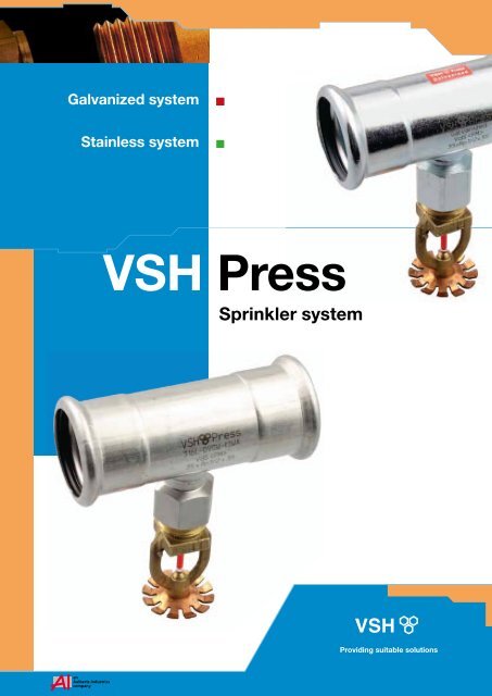
Galvanized system<br />
Stainless system<br />
<strong>VSH</strong> <strong>Press</strong><br />
Sprinkler system<br />
Providing suitable solutions
<strong>VSH</strong> <strong>Press</strong> Sprinkler system<br />
Your lightweight, easy and fast to install, cost-saving<br />
alternative for dry- and wet sprinkler installations.<br />
2<br />
Disclaimer:<br />
The technical data are not binding and not expressly warranted characteristics of the goods. These are subject to change.<br />
Please consult our General Conditions of Supply. Additional information is available upon request. It is the Designer’s responsibility<br />
to select products suitable for the intended service and to ensure that pressure ratings and performance data is not exceeded.<br />
Always read and understand the installation instructions. Never remove any piping components nor correct or modify any<br />
piping deficiencies without first depressurizing and draining the system.
Contents<br />
1 <strong>VSH</strong> Fittings B.V. 4<br />
2 <strong>VSH</strong> <strong>Press</strong> Sprinkler 5<br />
2.1 Introduction <strong>VSH</strong> <strong>Press</strong> Sprinkler 5<br />
2.2 Advantages of <strong>VSH</strong> <strong>Press</strong> Sprinkler 6<br />
3 <strong>VSH</strong> <strong>Press</strong> Sprinkler: a complete system 8<br />
3.1 <strong>VSH</strong> <strong>Press</strong> Sprinkler fittings 8<br />
3.2 <strong>VSH</strong> <strong>Press</strong> Sprinkler tube 10<br />
3.3 <strong>VSH</strong> <strong>Press</strong> Sprinkler tools 10<br />
3.4 <strong>VSH</strong> <strong>Press</strong> Flexible hoses 15<br />
4 Applications 17<br />
4.1 Fixed sprinkler systems 17<br />
5 Technical data and installation instructions 18<br />
5.1 O-ring 18<br />
5.2 <strong>VSH</strong> <strong>Press</strong> Sprinkler Tube 18<br />
5.3 Threaded couplings 19<br />
5.4 Flexible hoses technical data 20<br />
5.5 Installation instructions 20<br />
5.6 Minimum distance between fittings 22<br />
5.7 Available space needed for press tool 22<br />
5.8 Bending 23<br />
5.9 General instructions for use 24<br />
6 Certificates and approvals 27<br />
6.1 Design of sprinkler systems 27<br />
6.2 VdS certificate 28<br />
6.3 certificate 29<br />
7 Sprinkler product range 31<br />
7.1 <strong>VSH</strong> <strong>Press</strong> Sprinkler Galvanized system 31<br />
7.2 <strong>VSH</strong> <strong>Press</strong> Sprinkler Stainless system 37<br />
7.3 Tools and accessories 45<br />
3<br />
Providing suitable solutions
1 <strong>VSH</strong> Fittings B.V.<br />
<strong>VSH</strong> Fittings B.V. was founded in the early 1930s in Hilversum, the Netherlands, and has been<br />
a subsidiary of Aalberts Industries N.V. since 1991. The activities of <strong>VSH</strong> Fittings B.V. cover the<br />
development, production and sales of water, heating and gas piping systems.<br />
Over time the <strong>VSH</strong> product range has<br />
expanded as more and more fittings and<br />
accessories such as stop, gas and check<br />
valves were added to the range.<br />
Each time the deciding factor behind the<br />
product development of <strong>VSH</strong> was quality<br />
and ease of use for the installer.<br />
4<br />
Figure 1: <strong>VSH</strong> Fittings in the past<br />
<strong>VSH</strong> can now offer you a complete range of brass compression, stainless and carbon steel press<br />
fittings. The complete range of products is manufactured in Hilversum. We have established a<br />
good reputation through innovation, manufacturing of high quality products and a high level of<br />
service logistics. You can buy our products via wholesalers, sister companies which are part of<br />
Aalberts Industries and agencies.<br />
In the last few years <strong>VSH</strong> has developed more and more into a market oriented company.<br />
Customers’ wishes and needs are the starting point for the development and marketing of<br />
new products.<br />
Figure 2: <strong>VSH</strong> Fittings today
2 <strong>VSH</strong> <strong>Press</strong> Sprinkler<br />
2.1 Introduction <strong>VSH</strong> <strong>Press</strong> Sprinkler<br />
With the growing importance of the fire safety and security<br />
market on one hand and the lack of time on the building site<br />
on the other, making the <strong>VSH</strong> <strong>Press</strong> system available for<br />
sprinkler installations was an obvious choice.<br />
By obtaining the VdS approval in the beginning of 2008<br />
for both carbon and stainless steel, this was the start to<br />
evolve the <strong>VSH</strong> <strong>Press</strong> system into <strong>VSH</strong> <strong>Press</strong> Sprinkler.<br />
Many approvals, such as FM, FG, SBSC and CNBOP, have<br />
followed since and will continue to follow.<br />
Figure 3: <strong>VSH</strong> <strong>Press</strong> Sprinkler<br />
The application of <strong>VSH</strong> <strong>Press</strong> within sprinkler installations is focused on the risers, branch and<br />
distribution lines in the dimensions DN20-DN100 (22-108mm), either in carbon or stainless steel.<br />
<strong>VSH</strong> <strong>Press</strong> Sprinkler has been tested and certified for the use in wet (carbon and stainless steel)<br />
and dry (stainless steel) fixed sprinkler systems in accordance with international guidelines such<br />
as VdS and FM. The working pressure of the system can go up to 16 bar, depending on the<br />
dimensions and relevant approvals.<br />
5<br />
Wet fixed sprinkler systems<br />
Dry fixed sprinkler systems<br />
Figure 4: Area of application <strong>VSH</strong> <strong>Press</strong> Sprinkler<br />
Providing suitable solutions
2.2 Advantages of <strong>VSH</strong> <strong>Press</strong> Sprinkler<br />
In the building installation market the advantages of press systems over traditional solutions such<br />
as threading, soldering and welding have long been recognized. The same advantages apply for<br />
<strong>VSH</strong> <strong>Press</strong> in sprinkler installations:<br />
• Performance guaranteed<br />
• Reliable<br />
• Easy & clean<br />
• Safe<br />
• Speed<br />
Apart from these advantages, the aesthetics of a <strong>VSH</strong> <strong>Press</strong> installation (compared to e.g. black<br />
steel) are often a reason for architects and designers to prescribe our system for in-sight/exposed<br />
installations.<br />
6<br />
2.2.1 Performance guaranteed<br />
With all fittings being manufactured in our<br />
state-of-the-art factory in the Netherlands,<br />
<strong>VSH</strong> guarantees consistent quality and<br />
supply. High-tech manufacturing, using laser<br />
welding technology, ensures that all welded<br />
fittings are tested 100%. This leak test is<br />
entirely integrated and automated in the laser<br />
welding process. All straight connectors with<br />
a threaded end and reducers are made out<br />
of one piece, meaning no risk of leakage and<br />
short build-in dimensions.<br />
Figure 5: State-of-the-art production<br />
Performance in flow is obvious, with the extremely smooth surface of tubes and fittings, flow rates<br />
are much better than those in traditional solutions. The performance of our fittings can also be<br />
measured by the various number of national and international approvals. With certificates for<br />
drinking water, in house gas installations and now also sprinkler there is a wide range available of<br />
system and product approvals.<br />
2.2.2 Reliable<br />
In <strong>VSH</strong> <strong>Press</strong> Sprinkler systems, the quality<br />
of the connection is mainly determined by the tool and<br />
not the operator, therefore reducing the risk of<br />
installation mistakes. All fittings in the dimensions<br />
DN20-DN50 (22-54mm) are equipped with Leak Before<br />
<strong>Press</strong>ed (LBP) O-rings, to reduce this risk<br />
even further. This LBP function ensures that fittings,<br />
which have not been pressed, will leak during the initial<br />
pressure test. The installer can immediately see which<br />
fitting he forgot to press and correct this. Once pressed,<br />
the system is guaranteed water and air tight.<br />
Figure 6: Leak Before <strong>Press</strong>ed
2<br />
2.2.3 Easy & clean<br />
The <strong>VSH</strong> <strong>Press</strong> Sprinkler is an extremely user friendly solution:<br />
• No need to thread the tubes<br />
• No lubrication needed for installation<br />
• Easy tube insertion of the tube in the fitting due to the special <strong>VSH</strong> design of fittings<br />
• Short radius bends which ensure a compact installation<br />
Above features make sure that less skills for installation are required and that installation<br />
can take place in a more pleasant environment.<br />
2.2.4 Safe<br />
The installation of the <strong>VSH</strong> <strong>Press</strong> Sprinkler system does not require a heat<br />
source (as for example with welding or soldering) or other potentially heavy<br />
and dangerous tools. This feature makes <strong>VSH</strong> <strong>Press</strong> Sprinkler an ideal<br />
solution for retrofit or renovation projects, since you can ensure a minimum<br />
of disturbances during installation. Moreover, the light weight of the precision<br />
thin-wall steel tubes ensures improved labour conditions and as such brings<br />
a healthier way of working.<br />
7<br />
2.2.5 Speed<br />
Reduced labour time is probably the most important advantage of the <strong>VSH</strong> <strong>Press</strong> Sprinkler<br />
system, not only resulting in reduced costs but also important in times when it is difficult to<br />
find sufficiently skilled people to work on the projects.<br />
Based on given advantages, we are sure that the <strong>VSH</strong> <strong>Press</strong> Sprinkler system will have your<br />
preference for sprinkler installations in particular for distribution and branch systems.<br />
<strong>VSH</strong> <strong>Press</strong> Sprinkler system, an imPRESSive solution!<br />
Providing suitable solutions
3 <strong>VSH</strong> <strong>Press</strong> Sprinkler: a complete system<br />
When looking at more traditional connection methods, the products used in sprinkler installations<br />
are often approved as a product only. The <strong>VSH</strong> <strong>Press</strong> Sprinkler range is a complete system,<br />
where the combination of tube, fitting and tools are combined into a certified sprinkler system.<br />
The components of which our <strong>VSH</strong> <strong>Press</strong> Sprinkler system consist are:<br />
• <strong>VSH</strong> <strong>Press</strong> Sprinkler fittings either in carbon or stainless steel in the dimensions 22-108 mm<br />
• <strong>VSH</strong> <strong>Press</strong> Sprinkler tubes, which can be Sendzimir tube in combination with our carbon steel<br />
fittings, but also 3 different grades of stainless steel for our stainless steel fittings, depending<br />
on relevant approvals<br />
• <strong>VSH</strong> <strong>Press</strong> Sprinkler press tools, either battery or mains operated<br />
• Accessories such as our flexible hoses, especially adapted for an optimal combination<br />
with our <strong>VSH</strong> <strong>Press</strong> Sprinkler fittings and installation tools<br />
8<br />
3.1 <strong>VSH</strong> <strong>Press</strong> Sprinkler fittings<br />
The connection between the tube and the fitting is created by pressure using a press tool.<br />
The fitting sleeve is deformed and adapts to the surface of the tube, which is then pressed in<br />
turn against the sealing rings on the surface of the fitting. This process ensures the sealing<br />
effect and prevents the tube from slipping out. <strong>VSH</strong> <strong>Press</strong> fittings are produced and compatible<br />
with the so-called “M” pressing contour.<br />
before pressing<br />
Figure 7: <strong>Press</strong>ing before and after<br />
after pressing<br />
You can recognize the <strong>VSH</strong> <strong>Press</strong> Sprinkler range by the laser marking on the fitting which makes<br />
it easy for you to identify the fitting used. Information such as material, approvals and dimensions<br />
are all durably marked onto the fitting.<br />
<strong>VSH</strong> <strong>Press</strong> Sprinkler Galvanized fitting<br />
Laser marking<br />
<strong>Press</strong><br />
Galvanized<br />
Approvals<br />
Dimension<br />
Packaging Label<br />
Type C.....<br />
Dimension<br />
Description: ...C-Pr<br />
EAN Nr.<br />
Art. Nr. <strong>VSH</strong><br />
Approvals<br />
Number of pieces<br />
Table 1: Identification marking for carbon steel <strong>VSH</strong> <strong>Press</strong> fittings
3<br />
<strong>VSH</strong> <strong>Press</strong> Sprinkler Stainless fitting<br />
Laser marking<br />
<strong>Press</strong><br />
316L<br />
Approvals<br />
Dimension<br />
Packaging Label<br />
Type R.....<br />
Dimension<br />
Description: ...S-PR<br />
EAN Nr.<br />
Art. Nr. <strong>VSH</strong><br />
Approvals<br />
Number of pieces<br />
Table 2: Identification marking for stainless steel <strong>VSH</strong> <strong>Press</strong> fittings<br />
All <strong>VSH</strong> <strong>Press</strong> fittings in the sizes DN20 to DN50 (22-54 mm) are equipped with a LBP sealing ring<br />
as standard, to reduce the risk of installation errors.<br />
Figure 8: Detection of leaking fittings<br />
9<br />
Thanks to the special grooves in the<br />
O-ring (figure 9) the Leak Before <strong>Press</strong>ed<br />
O-ring (LBP) ensures optimum control of<br />
the system during pressure testing (such as<br />
for example described in the CEA 4001, no.<br />
17.1.1). Unpressed connections will leak water<br />
resulting in pressure loss and are afterwards<br />
easy to detect (figure 8). During the pressing<br />
procedure the O-ring deforms, closing the<br />
special grooves, and the connection between<br />
the tube and fittings is sealed, ensuring a<br />
water tight connection.<br />
Figure 9: LBP profile<br />
The <strong>VSH</strong> <strong>Press</strong> Sprinkler fittings are available either in carbon or in stainless steel. The carbon<br />
steel fittings are manufactured from unalloyed steel (material 1.0034/St 34-2) and are protected<br />
against corrosion by means of a zinc layer (8-15 μm) which is applied by electroplating.<br />
The stainless steel fittings are manufactured from stainless steel (material 1.4404 /AISI 316L).<br />
<strong>VSH</strong> <strong>Press</strong> Sprinkler fittings are equipped with an EPDM O-ring as standard in the dimensions<br />
DN20 to DN100 (22-108 mm).<br />
<strong>VSH</strong> <strong>Press</strong> Sprinkler fittings are available in the dimensions DN20 to DN100 (22-108 mm).<br />
Providing suitable solutions
3.2 <strong>VSH</strong> <strong>Press</strong> Sprinkler tube<br />
<strong>VSH</strong> <strong>Press</strong> Sprinkler tubes are available in the dimensions DN20 to DN100 (22-108 mm). Entry of<br />
dirt during transportation or storage is prevented by caps at both ends of the tube and utilizing<br />
the correct packaging for distribution.<br />
Fire behaviour<br />
<strong>VSH</strong> <strong>Press</strong> Sprinkler tubes are classified as non-combustible tubes of building material class A,<br />
DIN 4102, part 1.<br />
10<br />
3.2.1 <strong>VSH</strong> <strong>Press</strong> Sprinkler Galvanized<br />
The <strong>VSH</strong> <strong>Press</strong> Sprinkler Galvanized tubes for wet sprinkler systems are thin-walled precision<br />
steel tubes. The tubes are made from cold rolled steel that is galvanized using the Sendzimir<br />
process. During this process zinc is brought onto the metal strip, running through<br />
a zinc bath, covering both sides simultaneously. The tube is protected both on the<br />
inside and outside with a zinc layer. The thickness of this layer is minimal 20 μm.<br />
After welding the welding seam is zinc plated additionally. With the Sendzimir<br />
process a good adhesion of the zinc layer and corrosion resistance are achieved.<br />
3.2.2 <strong>VSH</strong> <strong>Press</strong> Sprinkler Stainless<br />
The <strong>VSH</strong> <strong>Press</strong> Sprinkler Stainless tubes are suitable for wet and dry sprinkler<br />
systems and are also thin-walled precision steel tubes. The outer- and inner<br />
surfaces of the tubes are blank, free of discoloration and are supplied free of<br />
manufacturing residue that could otherwise cause corrosion. The strict size<br />
tolerances and welding seam quality are checked on both the outside and inside.<br />
3.3 <strong>VSH</strong> <strong>Press</strong> Sprinkler tools<br />
Figure 10: <strong>VSH</strong> <strong>Press</strong> Sprinkler tube<br />
An important part of the <strong>VSH</strong> <strong>Press</strong> Sprinkler range are the press tools which are used to make<br />
a press connection. The tools which we prescribe for the <strong>VSH</strong> <strong>Press</strong> Sprinkler range consist of a<br />
press machine and the accompanying press jaws or slings. Depending on the outside diameter of<br />
the tube, you should choose the corresponding press jaws or slings to ensure a completely tight<br />
connection.<br />
Novopress<br />
Klauke<br />
Comfort line<br />
Basic line<br />
Big <strong>Press</strong><br />
ECO<br />
ACO<br />
EFP<br />
AFP<br />
UAP<br />
201/202<br />
201/202<br />
201/202<br />
201/202 100<br />
301<br />
401<br />
Figure 11: Sprinkler approved machines Novopress and Klauke
3<br />
Only tools made by Novopress for the dimensions DN20 to DN100 (22-108 mm) or Klauke for the<br />
dimensions DN65 to DN100 (76,1-108 mm) (suitable for M-Profile) are permitted to be used in<br />
combination with the <strong>VSH</strong> <strong>Press</strong> Sprinkler system. Other brands of machines and press jaws<br />
and slings are currently not permitted due to the certification of our sprinkler range. The following<br />
machines, press jaws and slings made by Novopress and Klauke are approved.<br />
3.3.1 Range of approved Novopress press machines<br />
Novopress ECO 202 DN20-32 (22-35 mm)<br />
Power supply<br />
Power<br />
Piston force<br />
Piston stroke<br />
Dimensions L x W x H<br />
Weight<br />
Novopress ACO 202 DN20-32 (22-35 mm)<br />
Power supply<br />
Power<br />
Piston force<br />
Piston stroke<br />
Dimensions L x W x H<br />
Weight<br />
220 - 240 V / 50 Hz<br />
400 W<br />
32 kN<br />
40 mm<br />
429 x 72 x 92 mm<br />
3,9 kg<br />
18 V / 3,0 Ah<br />
400 W<br />
32 kN<br />
40 mm<br />
410 x 80 x 125 mm<br />
3,3 kg<br />
11<br />
• Suitable for dimensions from DN20 to DN32 (22-35 mm)<br />
• ECO is mains operated, ACO battery operated with Li-Ion technology<br />
• The low weight and ergonomic shape render even narrow press areas readily accessible<br />
• Convenience features, such as the electronically controlled press procedure with automatic<br />
return and electronic retaining bolt securing device, guarantee perfect pressing<br />
• The diagnostic function enables optimum fault analysis for targeted servicing<br />
• Short press cycles, irrespective of the nominal widths, guarantee fast and economical working<br />
procedures<br />
Novopress EFP 202 DN20-32 (22-35 mm)<br />
Power supply<br />
Power<br />
Piston force<br />
Piston stroke<br />
Dimensions L x W x H<br />
Weight<br />
220 - 240 V / 50 Hz<br />
400 W<br />
32 kN<br />
40 mm<br />
446 x 85 x 220 mm<br />
4,1 kg<br />
Novopress AFP 202 DN20-32 (22-35 mm)<br />
Power supply<br />
Power<br />
Piston force<br />
Piston stroke<br />
Dimensions L x W x H<br />
Weight<br />
14,4 V / 2,4 Ah<br />
400 W<br />
32 kN<br />
40 mm<br />
385 x 85 x 240 mm<br />
3,9 kg<br />
Providing suitable solutions
• Suitable for dimensions from DN20 to DN32 (22-35 mm)<br />
• EFP is mains operated, AFP battery operated<br />
• The mechanical retaining bolt securing device guarantees that the press jaw is firmly in place<br />
at all times<br />
• Due to its slender dimensions, this robust device, which is suitable for construction site use,<br />
makes even narrow press areas readily accessible<br />
• A powerful motor enables extremely short press times irrespective of the nominal widths and<br />
guarantees fast and economical working procedures<br />
Novopress ECO 301 DN20-50 (22-54 mm)<br />
Power supply<br />
Power<br />
Piston force<br />
Piston stroke<br />
Dimensions L x W x H<br />
Weight<br />
220 - 240 V / 50 Hz<br />
560 W<br />
45 kN<br />
45 mm<br />
420 x 85 x 110 mm<br />
5,0 kg<br />
12<br />
• Compact dimensions, suitable for dimensions from DN20 to DN50 (22-54 mm)<br />
• ECO 301 is mains operated<br />
• Control and monitoring of the entire press cycle is carried out by a microprocessor which<br />
ensures optimum press performance at all times over the entire period of use<br />
• The simple operation and ergonomic design render even narrow press areas readily accessible<br />
• The electronic retaining bolt securing device and automatic return after completion of the press<br />
cycle are tried and tested standards<br />
• Fast and economical. Short press cycles of approx. 12 seconds irrespective of the nominal widths<br />
Novopress ACO401 DN65-100 (76,1-108 mm)<br />
Power supply<br />
Power<br />
Piston force<br />
Piston stroke<br />
Dimensions L x W x H<br />
Weight<br />
18 V / 3,0 Ah<br />
400 W<br />
100 kN<br />
60 mm<br />
660 x 100 x 250 mm<br />
13,0 kg<br />
The ACO401 pressmachine is a perfect solution for fire sprinkler systems, potable water, ship building<br />
and industrial purposes. The dimensions DN65 upto DN100 (76,1-108 mm) can be pressed in a<br />
safe and reliable way by using the special HP401 slings.<br />
• Control and monitoring of the entire press cycle is carried out by a microprocessor which ensures<br />
optimum press performance at all times over the entire period of use<br />
• The simple hand operation of the machine allows the installer work at locations that are difficult<br />
to access (e.g. ceilings)<br />
• Automatic processing including the return after completion of the press cycle is a proven standard<br />
• <strong>Press</strong> cycles of ca. 25 seconds, independent of nominal diameter enable fast and economical<br />
performance<br />
• The cylinder including sling adaptor can be turned 180° and enables installation at difficult access<br />
locations
3<br />
3.3.2 Approved Novopress jaws and slings<br />
Depending on the outside diameter of the tube the pressing should be executed with a press jaw<br />
or a press sling. In the dimensions 22 and 28 mm a regular press jaw from Novopress can be<br />
used. When going to bigger dimensions the pressing should be done by means of a press sling<br />
(starting from 35 mm). The dimensions 42 and 54 mm are pressed with a special <strong>VSH</strong> power sling,<br />
which have 4 segments instead of 3 segments. These special <strong>VSH</strong> Power Slings are especially<br />
designed for the <strong>VSH</strong> <strong>Press</strong> Sprinkler system.<br />
Novopress jaws and slings<br />
<strong>Press</strong> jaws<br />
<strong>Press</strong> slings<br />
DN / dimension<br />
Nominal width (mm)<br />
20 22<br />
25 28<br />
32 35<br />
40 42<br />
50 54<br />
65 76,1<br />
80 88,9<br />
100 108<br />
Table 3: Overview of Novopress press jaws and press slings<br />
Special care should be taken in the combination of press machine and press sling. Always make<br />
sure to use the appropriate adapter. In the table below you can find the different combinations<br />
approved of machine and press jaw and sling.<br />
13<br />
<strong>Press</strong>ing tool ECO 301<br />
ECO 301 jaw<br />
ECO 301 jaw<br />
<strong>Press</strong> sling 35<br />
<strong>VSH</strong> <strong>Press</strong> power sling<br />
<strong>VSH</strong> <strong>Press</strong> power sling<br />
Table 4: <strong>Press</strong>ing with ECO 301<br />
<strong>Press</strong>ing tool ACO 401<br />
<strong>Press</strong> sling HP 401 76,1<br />
<strong>Press</strong> sling HP 401 88,9<br />
<strong>Press</strong> sling HP 401 108<br />
DN / dimension Nominal width (mm) Adapter<br />
20 22<br />
25 28<br />
32 35 ZB 302<br />
40 42 ZB 302<br />
50 54 ZB 302<br />
DN / dimension Nominal width (mm) Adapter<br />
65 76,1<br />
80 88,9<br />
100 108<br />
Table 5a: <strong>Press</strong>ing with ACO 401<br />
<strong>Press</strong>ing tools ECO 201/202 ACO 201/202, EFP 2, EFP 201/202 & AFP 201/202<br />
ECOTEC jaw<br />
ECOTEC jaw<br />
<strong>Press</strong> sling 35<br />
DN / dimension Nominal width (mm) Adapter<br />
20 22<br />
25 28<br />
32 35 ZB 201<br />
Table 5b: <strong>Press</strong>ing with ECO 201/202, ACO 201/202, EFP 2, EFP 201/202 and AFP 201/202 press tools<br />
Providing suitable solutions
3.3.3 Range of approved Klauke press machines<br />
Klauke UAP 100 DN65-100 (76,1-108 mm)<br />
Power supply (main)<br />
Power supply (battery)<br />
Piston force<br />
Dimensions L x W x H<br />
Weight<br />
230 V / 50 Hz<br />
12 V / 3 Ah<br />
120 kN<br />
577 x 173 x 96 mm<br />
13,0 kg<br />
14<br />
• Compact dimensions, suitable for dimensions from DN65 to DN100 (76,1-108 mm)<br />
• With integrated adapter for the press slings<br />
• Entire press cycle is controlled and monitored by a microprocessor<br />
• 360 degrees rotatable press head<br />
• Easy operation and ergonomic design (even narrow press areas readily accessible)<br />
• Electronic retaining bolt securing device and automatic return after completion of the press cycle<br />
• Fast and economical. <strong>Press</strong>ing cycle of 24-36 seconds (depending on dimension)<br />
3.3.4 Approved Klauke slings<br />
<strong>Press</strong> slings UAP 100 DN65-100 (76,1-108 mm)<br />
<strong>Press</strong> sling DN / dimension Nominal width (mm)<br />
KSP 3 65 76,1<br />
KSP 3 80 88,9<br />
KSP 3 100 108<br />
Table 6: Overview of Klauke press slings<br />
If the press tools referred to in tables 4, 5a, 5b and 6 are correctly used, reliable pressing with the<br />
<strong>VSH</strong> <strong>Press</strong> Sprinkler system is guaranteed. Regular maintenance and lubrication of the press<br />
jaws, slings, adapters and tools is required. Please see the Novopress and Klauke instructions<br />
for use and maintenance.
3<br />
3.4 <strong>VSH</strong> <strong>Press</strong> flexible hoses<br />
The lining up of sprinklers using rigid piping in<br />
suspended ceiling systems can be very time<br />
consuming and costly. The use of <strong>VSH</strong> <strong>Press</strong><br />
flexible hoses for sprinkler installations<br />
enables a quick and easy connection of<br />
sprinkler heads within a circular area defined<br />
by the hose length. With the flexible sprinkler<br />
hoses it is possible to mount sprinklers in<br />
suspended ceilings systems without any<br />
problems, resulting in significant time and<br />
cost savings.<br />
Figure 12: Flexible hoses<br />
The supplied mounting brackets ensure a reliable and secure attachment of the sprinkler hose to<br />
the ceiling system substructure.<br />
15<br />
The <strong>VSH</strong> <strong>Press</strong> flexible hoses are part of the <strong>VSH</strong> <strong>Press</strong> Sprinkler VdS approval for fixed sprinkler<br />
installations. <strong>VSH</strong> can offer you 2 versions, either with a straight end or an angle of 90°. Available<br />
dimensions are DN20 and DN25 in the lengths 800, 1000, 1500 and 2000 mm.<br />
Application<br />
The <strong>VSH</strong> <strong>Press</strong> flexible hoses are suitable to be installed in:<br />
• I-beam lay-in ceiling systems with mineral fiber panels and metal cassettes<br />
(main and ancillary profiles)<br />
• Clamping profile ceiling systems<br />
• Plasterboard ceiling systems<br />
• Suspension-mounted standard sprinklers<br />
• Hidden or recessed sprinklers<br />
The special feature of these hoses is the<br />
straight pipe which is 100% compatible to<br />
the <strong>VSH</strong> <strong>Press</strong> Sprinkler system. The straight<br />
pipe end assures an easy connection from<br />
the flexible hose to the <strong>VSH</strong> <strong>Press</strong> Sprinkler<br />
systems. Where with threaded connections<br />
the whole hose needs to be rotated, with the<br />
straight pipe end you only need to position the Figure 13: Straight pipe end<br />
pipe end in the fitting and you are ready for pressing.<br />
Providing suitable solutions
3<br />
Advantages<br />
• Simple and quick installation with the flexible sprinkler hose using standard tooling<br />
• Entire sprinkler hose is made of stainless steel<br />
• Easy bypass of other parts and building components<br />
• No rotation of complete hose during installation because of straight pipe end<br />
• Flexibility of positioning the sprinkler mounting system across the ceiling panel<br />
• No bending or lifting of ceiling elements as sprinkler hose is fixed on ceiling substructure<br />
• Where leaks on rigid piping systems can only be detected when the ceiling panels have already<br />
been installed, leaks on sprinkler systems equipped with flexible hose are already detected in<br />
building shells. Expensive water damage can thus be prevented<br />
• The sprinkler system does not need to be reinstalled for renovation or conversion. Hoses and<br />
brackets can be dismounted and remounted at the new location without emptying the complete<br />
installation, within the circular area defined by the hose length<br />
• Easy vertical positioning due to scaling on sprinkler sleeve<br />
16<br />
Length (mm)<br />
Sprinkler<br />
discharge<br />
Sprinkler<br />
connection<br />
Pipe conn.<br />
(mm)<br />
<strong>Press</strong>. loss*<br />
(bar)<br />
Equiv. pipe<br />
length* (m)<br />
1000 straight<br />
Rp ½” Ø22 0,9 8<br />
1500 straight<br />
Rp ½” Ø22 1,3 12<br />
2000 straight<br />
Rp ½” Ø22 1,7 14<br />
1000 straight<br />
Rp ½” Ø28 0,5 8<br />
1500 straight<br />
Rp ½” Ø28 0,8 11<br />
2000 straight<br />
Rp ½” Ø28 1,0 12<br />
800 90° angle<br />
Rp ½” Ø22 0,8 8<br />
1000 90° angle<br />
Rp ½” Ø22 0,9 8<br />
1500 90° angle<br />
Rp ½” Ø22 1,3 12<br />
800 90° angle<br />
Rp ½” Ø28 0,5 8<br />
1000 90° angle<br />
Rp ½” Ø28 0,5 8<br />
1500 90° angle<br />
Rp ½” Ø28 0,8 11<br />
Table 7 * <strong>Press</strong>ure losses and equivalent pipe lengths correspond with VdS specifications<br />
Flexible sprinkler hoses suitable for <strong>VSH</strong> <strong>Press</strong> Sprinkler; flexible, simple, secure and<br />
cost saving.
4<br />
4 Applications<br />
4.1 Fixed sprinkler systems<br />
Figure 14: Sprinkler installation <strong>VSH</strong> <strong>Press</strong> Sprinkler<br />
Fixed sprinkler systems are permanently<br />
installed fire extinguishing and fire protection<br />
systems, which independently detect and<br />
report a fire and automatically start the<br />
extinguishing process. The installation of<br />
the <strong>VSH</strong> <strong>Press</strong> Sprinkler system in sprinkler<br />
systems is carried out in accordance with<br />
appropriate guidelines (e.g. VdS-CEA 4001).<br />
Depending on the material installed (stainless<br />
or carbon steel), the system can either be<br />
used in wet or dry fixed sprinkler systems.<br />
<strong>VSH</strong> <strong>Press</strong> Sprinkler Galvanized is only suitable<br />
for use in fixed wet sprinkler systems,<br />
where <strong>VSH</strong> <strong>Press</strong> Sprinkler Stainless can be<br />
used in both wet and dry fixed sprinkler<br />
systems.<br />
17<br />
With different approvals under which the <strong>VSH</strong> <strong>Press</strong> Sprinkler system is installed, also different<br />
hazard classes apply.For more detailed information on applicable hazard classes, please contact<br />
your <strong>VSH</strong> representative, or <strong>VSH</strong> Fittings directly.<br />
When the <strong>VSH</strong> <strong>Press</strong> Sprinkler system is used, it should also be ensured that no loads can fall onto<br />
the tube network under normal conditions or in the case of a fire; for example ventilation ducts and<br />
cable trays should not be installed above the sprinkler tubes. Depending on your type of system<br />
and the approval which applies to your fixed sprinkler system, different fastener distances apply.<br />
In sprinkler applications the fastener distances for steel press systems are based on the values<br />
used for copper tube. Always follow the valid local guidelines and please make sure to follow<br />
these fastener distances correctly.<br />
DN Tube dimension Fastener distances (m)<br />
CEA 4001 (VdS) NFPA 13 DIN 1988-2<br />
20 22 2,00 2,44 2,00<br />
25 28 2,00 2,44 2,25<br />
32 35 2,00 3,66 2,75<br />
40 42 2,00 3,66 3,00<br />
50 54 3,00 3,05 3,50<br />
65 76,1 3,00 3,05 4,25<br />
80 88,9 3,00 3,05 4,75<br />
100 108 3,00 3,05 5,00<br />
Table 8: Fastener distances for sprinkler tubes<br />
Providing suitable solutions
5 Technical data and installation instructions<br />
5.1 O-ring<br />
The <strong>VSH</strong> <strong>Press</strong> Sprinkler fittings are supplied with an EPDM Leak Before <strong>Press</strong>ed O-ring in the<br />
dimensions DN20-DN50 (22-54 mm) with the following data:<br />
Technical data of the <strong>VSH</strong> <strong>Press</strong> LBP EPDM O-ring<br />
Material<br />
EPDM<br />
Colour<br />
black<br />
Coating<br />
Silicone-free<br />
Min./max. temperature (ºC)<br />
-35ºC up to +135ºC<br />
Max. short-term operating temperature (ºC) 150ºC<br />
Max. operating pressure (bar)<br />
16 bar<br />
Fields of operation<br />
Wet and dry tube sprinkler systems<br />
Table 9: Dimensions and technical data for the <strong>VSH</strong> <strong>Press</strong> LBP EPDM O-ring<br />
18<br />
For the dimensions DN65-DN100 (76,1-108mm) all fittings are supplied with a standard<br />
EPDM O-ring:<br />
Technical data of the <strong>VSH</strong> <strong>Press</strong> EPDM O-ring<br />
Material<br />
EPDM<br />
Colour<br />
black<br />
Coating<br />
Silicone-free<br />
Min./max. temperature (ºC)<br />
-20ºC until +85ºC<br />
Max. short-term operating temperature (ºC) 120ºC<br />
Max. operating pressure (bar)<br />
16 bar<br />
Fields of operation<br />
Wet and dry tube sprinkler systems<br />
Table 10: Technical data <strong>VSH</strong> <strong>Press</strong> EPDM O-ring<br />
5.2 <strong>VSH</strong> <strong>Press</strong> Sprinkler Tube<br />
5.2.1 Dimensions<br />
Dimensions of <strong>VSH</strong> <strong>Press</strong> Sprinkler Galvanized tube<br />
DN Nominal width<br />
(mm)<br />
Wall thickness<br />
(mm)<br />
Wall thickness<br />
tolerance (mm)<br />
20 22 1,5 ± 0,15<br />
25 28 1,5 ± 0,15<br />
32 35 1,5 ± 0,15<br />
40 42 1,5 ± 0,15<br />
50 54 1,5 ± 0,15<br />
65 76,1 2,0 ± 0,20<br />
80 88,9 2,0 ± 0,20<br />
100 108 2,0 ± 0,20<br />
Table 11: Dimensions of <strong>VSH</strong> <strong>Press</strong><br />
Sprinkler Galvanized tube<br />
Dimensions of <strong>VSH</strong> <strong>Press</strong> Sprinkler Stainless tube<br />
DN Nominal width<br />
(mm)<br />
Wall thickness<br />
(mm)<br />
Wall thickness<br />
tolerance (mm)<br />
20 22 1,2 ± 0,10<br />
25 28 1,2 ± 0,10<br />
32 35 1,5 ± 0,10<br />
40 42 1,5 ± 0,10<br />
50 54 1,5 ± 0,10<br />
65 76,1 2,0 ± 0,15<br />
80 88,9 2,0 ± 0,15<br />
100 108 2,0 ± 0,15<br />
Table 12: Dimensions of <strong>VSH</strong> <strong>Press</strong><br />
Sprinkler Stainless tube
5.2.2 Material specifications<br />
Material specifications of <strong>VSH</strong> <strong>Press</strong> Sprinkler Galvanized tube<br />
Material Unalloyed ULC (’Ultra Light Carbon’) C-steel, E190 part no. 1.0031 according EN 10305-3<br />
Specifications<br />
EN10305-3<br />
Approvals<br />
VdS, FM, FG, CNBOP, SBSC<br />
Type of tubing<br />
HF welded<br />
Welding deterioration reduction 100% EDDY CURRENT tested according to SEP 1925<br />
Weld slag removal<br />
Outside weld flat, insight raising max. 0,5 mm, for dimensions >54 mm 0,8 mm<br />
Tolerances<br />
According to EN10305-3<br />
Finishing<br />
Zinc coating of at least 20μm according steel grade ZNT275. The tube welding seam is subsequently<br />
galvanized on the outside.<br />
Surface finish<br />
Silver-coloured<br />
Marking<br />
<strong>VSH</strong> <strong>Press</strong> Sprinkler Galvanized, DN/size x wall thickness mm, VdS, G4080007, 16.0 bar, batch number<br />
+ production date<br />
Smallest bending radius 3,5 x external diameter of the tube (max. 28 mm)<br />
Supply mode<br />
Tubes, length of 6 m +0/-50 mm, with protective caps<br />
Heat expansion coefficient 0,0108 mm/m with ∆T= 1K<br />
Max. operating pressure 16 bar<br />
Table 13: Technical data of the <strong>VSH</strong> <strong>Press</strong> Sprinkler Galvanized tube<br />
Material specifications of <strong>VSH</strong> <strong>Press</strong> Sprinkler Stainless tube<br />
1.4401 1.4521 1.4520<br />
Material X5CrNiMo 17 12 2 Material no. 1.4401<br />
according to DIN-EN 10088-2<br />
X2CrMoTi 18 2 Material no. 1.4521<br />
according to DIN-EN 10088-2<br />
X2CrTi17 Material no. 1.4520<br />
according to DIN-EN 10088-2<br />
Specifications EN 10312 – DVGW worksheet GW541 (2004) EN 10312 – DVGW worksheet GW541 EN 10296-2<br />
Row 2<br />
(2004) Table 2<br />
Approvals DVGW, SVGW, ETA, ÖVGW, BYGGFORSK, DVGW, SVGW, ETA, FM, ÖVGW, FG FM, FG<br />
STF, PZH, SITAC, CSTBat, WRAS, VdS, FM,<br />
FG, CNBOP, SBSC<br />
Type of tubing TIG or laser welded Laser welded Laser welded<br />
Welding<br />
deterioration<br />
reduction<br />
100% EDDY CURRENT tested according to<br />
SEP 1914/ EN 10246-2<br />
100% EDDY CURRENT tested<br />
according to SEP 1914/ EN 10246-2<br />
100% EDDY CURRENT tested<br />
according to SEP 1914/ EN 10246-<br />
2<br />
Weld slag Outside Outside Outside<br />
removal<br />
Tolerances According to EN 10312 According to EN 10312 According to EN 10296-2<br />
Finishing Annealed under a protective atmosphere<br />
W2R<br />
Annealed under a protective<br />
atmosphere W2R<br />
Annealed under a protective<br />
atmosphere W2R<br />
Surface finish Matt silver-coloured Matt silver-coloured Matt silver-coloured<br />
Marking<br />
Smallest<br />
bending radius<br />
Supply mode<br />
Heat<br />
expansion<br />
coefficient<br />
Max. operating<br />
pressure<br />
<strong>VSH</strong> X PRESS DN/size x wall thickness mm<br />
Edelstahl/Stainless steel - Sanitär/Sanitary<br />
- GAS 1.4401 W2R, EN10217-7 EN10312<br />
DVGW GW541 Reg.nr. DW-7301BM5610<br />
SVGW ÖVGW W1.397 WRAS ETA<br />
BYGGFORSK STF PZH SITAC(+symbol)<br />
0168/04 CSTBat(symbol) 14/04-88, VdS<br />
G4080037 16.0 bar, Production date/<br />
Production code<br />
3,5 x external diameter of the tube<br />
(max. 28 mm)<br />
Tubes, length of 6 m +0/-50 mm, with<br />
protective caps<br />
<strong>VSH</strong> X <strong>Press</strong> DN/size x wall thickness<br />
mm Edelstahl/Stainless steel, 1.4521,<br />
Sanitär/Sanitary - W2R EN10296-2<br />
EN10312DVGW GW541 reg. nr. DW-<br />
7301BP5610 SVGW ÖVGW ETA <br />
Production date/Production code<br />
<strong>VSH</strong> X <strong>Press</strong> DN/size x wall<br />
thickness mm Edelstahl/ Stainless<br />
steel, 1.4520 Heizung/Druckluft -<br />
Chauffage/Air Comprimé -<br />
Heating/Compressed Air <br />
Production date/Production code<br />
3,5 x external diameter of the tube<br />
(max. 28 mm)<br />
3,5 x external diameter of the tube<br />
(max. 28 mm)<br />
Tubes, length of 6 m +0/-50 mm, with Tubes, length of 6 m +0/-50 mm,<br />
protective caps<br />
with protective caps<br />
0,0160 mm/m with ∆T= 1K 0,0104 mm/m with ∆T= 1K 0,0104 mm/m with ∆T= 1K<br />
16 bar 16 bar 16 bar<br />
19<br />
Table 14: Technical data of the <strong>VSH</strong> <strong>Press</strong> Sprinkler Stainless tube (1.4401/1.4520/1.4521)<br />
5.3 Threaded couplings<br />
The <strong>VSH</strong> <strong>Press</strong> Sprinkler product range also comprises articles with internal and external thread<br />
for connection with other threaded parts of a tube network (for example sprinklers, valves,<br />
mountings). Internal and external threads are produced in accordance with DIN 2999/ISO 7/1.<br />
Providing suitable solutions
Teflon ® may be used as sealing material for the C-steel threads. Only industry standard chloride<br />
free sealants should be used to seal the thread connections in the case of stainless steel fittings.<br />
Teflon ® thread sealing band cannot be used in conjunction with stainless steel due to water-soluble<br />
chloride ions contained therein.<br />
For threaded connections we recommend that the pressed connections are not be subjected to a<br />
load.<br />
5.4 <strong>VSH</strong> <strong>Press</strong> flexible hoses technical data<br />
20<br />
Technical data <strong>VSH</strong> <strong>Press</strong> flexible hoses<br />
Sprinkler hose<br />
Type RS 339L92, DN20/DN25, flexible design with braiding, completely made of stainless steel,<br />
welded fittings<br />
Sprinkler connection (straight) Stainless steel bend pipe thread as per DIN EN 10226 (ISO 7/1), Rp½” (SW 27). Scaling for simple<br />
vertical alignment. Application when space is limited. Installation height (x) only 170 mm above lower<br />
edge of suspended ceiling<br />
Sprinkler connection (90° design) Stainless steel bend pipe thread as per DIN EN 10226 (ISO 7/1), Rp½” (SW 27). Scaling for simple<br />
vertical alignment. Application when space is limited. Installation height (x) only 170 mm above lower<br />
edge of suspended ceiling<br />
Connection to water supply Stainless steel straight pipe end with diameter of 22 or 28 mm to be connected with <strong>VSH</strong> <strong>Press</strong><br />
Sprinkler fittings<br />
Nominal length<br />
800, 1000, 1500 and 2000 mm<br />
Max. operating pressure<br />
16 bar, 100% leak tightness tested<br />
Table 15: Technical data flexible hoses<br />
5.5 Installation instructions<br />
Making a press connection is very easy, especially due to the light weight of fittings and tube and<br />
the machine controlled process which is taking place during the connection of tube and fitting.<br />
To always ensure an optimal connection between tube and fitting it is mandatory to follow up the<br />
installation instructions which are illustrated below, and which are also supplied on each bag of<br />
fittings.<br />
5.5.1 Transport and storage<br />
During transport and storage of <strong>VSH</strong> <strong>Press</strong> Sprinkler tubes and press fittings it is important to<br />
avoid damage and soiling. The best storage temperature for fittings and tubes is between 10°C<br />
and 25°C and they should be stored in a dry area (maximum humidity 65%). The storage of tubes<br />
should be horizontal, separated by wooden blocks. Don’t stack the bundles too high to prevent<br />
tubes from getting oval (the maximum height should not exceed 6 bundles, when stacking stack in<br />
2x2/3x3, etc.). Please make sure not to mix tube materials (carbon and stainless steel) in storage.<br />
5.5.2 Cutting the tube to size<br />
After the measurements have been taken, the <strong>VSH</strong> <strong>Press</strong> Sprinkler<br />
tube can be cut to size with a tube cutter, a fine-toothed handsaw<br />
or a mechanical saw with motor suitable for the tube material.<br />
1<br />
The tube should always be cut completely. Never partially cut the<br />
tube and then break it (this could cause corrosion).<br />
Do not use oil cooled saws, abrasive wheels or flame cutting.
5<br />
5.5.3 Deburring the tube<br />
The tube ends should be carefully deburred on the inside and<br />
outside after cutting to length to prevent damages to the sealing<br />
ring when the tube is inserted into the press fitting. Deburring can<br />
be carried out both on the inside and outside either using a manual<br />
or an electric deburring tool. Burrs sticking to the tube must<br />
be removed.<br />
2<br />
5.5.4 Insertion depth marking<br />
Mark the insertion depth on the tube in order to guarantee a safe and<br />
proper connection with a suitable marking tool as supplied by <strong>VSH</strong>.<br />
Reliable pressing with the corresponding tensile strengths can only<br />
be achieved by a proper installation. The pressing operation behind<br />
the crimp is of crucial importance for the tensile strength. The marking<br />
on the tube must remain visible (but close to the fitting) after the<br />
connection is pressed to identify any movement before or after pressing.<br />
5.5.5 Check the fitting and tube<br />
Before assembly, the fitting must be checked to ensure the correct<br />
position and presence of the O-rings. The tube, fitting and O-ring<br />
should be examined for foreign material (e.g. dirt, burrs), which should<br />
be removed if present.<br />
3<br />
4<br />
21<br />
5.5.6 Assembly of fitting and tube<br />
Insert the tube into the press fitting up to the marked insertion depth<br />
while being rotated slightly and pushed in an axial direction at the<br />
same time. The marking for the insertion depth must still be visible.<br />
In case of fittings without a stop the fittings should be inserted at<br />
least as far as the marked insertion depth.<br />
5<br />
Rough and careless insertion of the tube into the press fitting may<br />
result in damage to the O-ring and is therefore not permitted. When<br />
assembly is more difficult due to permitted tolerances in sizes,<br />
a lubricant as water or soap may be used, but never use oil or grease.<br />
Under no circumstances oils or grease may be used as lubricants<br />
For practical reasons and in order to optimize the installation time, it is standard procedure to<br />
establish a certain number of connections first before pressing the different connections one after<br />
the other.<br />
This makes it important to mark the insertion depth as described under 5.5.4<br />
Before the final pressing operation is carried out for the different tube connections, always check<br />
the minimum clearances which are listed in table 16.<br />
Providing suitable solutions
5.5.7 <strong>Press</strong>ing<br />
Before starting to press, the press jaws and slings must be checked for dirt, which must be<br />
removed if present. Furthermore, it must be ensured that the press machine is in good condition<br />
and that the instructions for operating the device, maintenance and the manufacturers’<br />
instructions have been followed. Also make sure that you use the correct press jaws and slings<br />
for the <strong>VSH</strong> <strong>Press</strong> Sprinkler application. In order to create a proper pressed connection, the<br />
groove of the press tool must enclose the press fitting O-ring bead. Once the pressing has<br />
started, always complete the press cycle and under no circumstances interrupt the process.<br />
It is not allowed to press a fitting twice or more<br />
6<br />
22<br />
5.6 Minimum distance between fittings<br />
The <strong>VSH</strong> <strong>Press</strong> fittings are all equipped with the M-profile.<br />
To ensure a proper mounting of the press jaws and slings<br />
there should always be a minimum clearance available<br />
between the fittings. Before the final pressing operation is<br />
carried out for the different tube connections, the minimum<br />
clearances must be checked (see table 16).<br />
Insertion depth<br />
Minimum distance<br />
between 2 pressings<br />
Minimum<br />
tube length required<br />
DN Aussen ø (mm)<br />
e (mm) A-min (mm) 2 x e + A-min (mm)<br />
L-min<br />
C-steel St. steel C-steel St. steel C-steel St. steel<br />
20 22 21 21 10 10 52 52<br />
25 28 23 23 10 10 56 56<br />
32 35 26 26 10 10 62 62<br />
40 42 30 30 20 20 80 80<br />
50 54 35 35 20 20 90 90<br />
65 76,1 55 55 40 40 165 165<br />
80 88,9 63 63 50 50 186 186<br />
100 108 77 77 50 50 234 234<br />
Table 16: Minimum distance between pressings<br />
5.7 Available space needed for press tool<br />
Using a press tool including the press jaws and slings can be limited due to the available space<br />
for the press tool. To make sure that there is enough space available for the press tool, please<br />
make sure to follow the minimum distances in the table below. Table 17 lists the important<br />
minimum distances and the space requirement for an installation in order to guarantee correct<br />
processing.
5<br />
The sizes refer to the general installation geometries and are shown schematically<br />
in illustrations 15, 16 and 17.<br />
a<br />
d a<br />
b<br />
c<br />
b<br />
Figure 15 Figure 16 Figure 17<br />
Figure 15 Figure 16 Figure 17<br />
DN<br />
20<br />
External ø (mm)<br />
22<br />
a<br />
65<br />
b<br />
25<br />
a<br />
80<br />
b<br />
31<br />
c<br />
35<br />
d<br />
150<br />
Tube depth (mm)<br />
40<br />
25 28 75 25 80 31 35 150 60<br />
32 35* 115 75 115 75 75 265 70<br />
40 42* 120 75 115 75 75 265 70<br />
50 54* 200 85 120 85 85 290 70<br />
65 76,1* 250 170 200 170 190 390 80<br />
80 88,9* 250 170 250 170 210 460 90<br />
100 108* 250 170 250 170 210 460 100<br />
23<br />
Table 17: Space needed for installation (* press slings)<br />
5.8 Bending<br />
Depending on the system, it may be necessary to bend the tube during installation. For this, commercially<br />
available manual, hydraulic or electric bending tools with the corresponding bending<br />
segments are used. The suitability of the bending tool is defined by the manufacturer. <strong>VSH</strong> <strong>Press</strong><br />
Sprinkler tubes for sprinkler installations are cold pliable in the sizes 22 and 28 mm.<br />
The minimum bending radius is as follows:<br />
Carbon and stainless steel tube<br />
<strong>VSH</strong> <strong>Press</strong> flexible hoses<br />
Rmin = 3,5 x d (max. 28 mm)<br />
22 mm = 70 mm<br />
28 mm = 85 mm<br />
Due to the danger of corrosion the tube must not be bent when it is warm<br />
Providing suitable solutions
5.9 General instructions for use<br />
5.9.1 Flushing the network<br />
After completion of the installation work the entire sprinkler system has to be thoroughly rinsed<br />
through with filtered (drinking) water. Flushing of the system is necessary in order to guarantee<br />
that it is working correctly and to prevent contamination within the system. After the system has<br />
been rinsed through it has to be drained off. The sprinklers then have to be attached after the<br />
removal of all the materials required for flushing the network.<br />
5.9.2 Filling and bleeding the tube network<br />
After flushing of the tube network has been carried out, the network should be filled with filtered<br />
drinking water and completely bled.<br />
24<br />
5.9.3 <strong>Press</strong>ure testing<br />
The tubes belonging to the sprinkler system must be subjected to a pressure test according to<br />
valid guidelines, for example CEA 4001, no. 17.1.1. (VdS) lasting at least two hours. During the<br />
test a pressure (measured at the alarm valves) corresponding to 1,5 times the permitted positive<br />
operating pressure - but at least 15 bar - must be maintained. This pressure test is a check of<br />
both the strength and tightness of the system. The pressure loss, for example due to temperature<br />
changes, should be monitored for 24 h. Dry sprinkler systems shall also be tested pneumatically<br />
to a pressure of not less than 2,5 bars for not less than 24 hours. Every leakage which occurs and<br />
results in a pressure drop of more than 0,15 bar for the 24 h, shall be corrected.<br />
Any faults disclosed, such as permanent deformations, ruptures or leakages shall be corrected,<br />
and the pressure test must be repeated.<br />
5.9.4 Flow loss<br />
Every fluid that flows through a tubing system experiences continuous and local flow resistances<br />
that are apparent from the pressure drop in the system. There is a difference between the continuous<br />
and the local pressure drop. The continuous pressure drop is mainly caused by the flow<br />
resistance in straight tube sections, which in turn essentially results from the friction between the<br />
fluid and the tube wall.<br />
Local pressure drops, on the contrary, are those flow resistances that are caused by turbulence,<br />
for instance where there is a change of internal tube diameter, a tube branch, in an elbow, etc.<br />
5.9.5 Continuous pressure drop<br />
To calculate the total pressure drop resulting from the flow of fluids in a straight section of the<br />
tubing system, first determine the pressure drop over a unit of length and then multiply the total<br />
length with this value. This value can be determined analytically using the Hazen-Williams formula.<br />
6,05 x 10 5<br />
p = ------------------------- x Q 1,85<br />
C 1,85 x di 4,87<br />
p = pressure loss in the tube [bar/m]<br />
Q = flow through the tube [l/min]<br />
di = mean internal diameter of the tube [mm]<br />
C = constant for type and condition of the tube<br />
C=140 for <strong>VSH</strong> <strong>Press</strong> Sprinkler tube<br />
The pressure loss due to velocity may be ignored.
5<br />
5.9.6 Local pressure drops<br />
Local pressure drop is, as mentioned in the introduction of this section, the resistance to flow<br />
that results from changes in the flow direction and cross-sectional area, flow splitting over several<br />
channels, etc. There are in general two possibilities to calculate these flow resistances: the direct<br />
analytical method and the method using equivalent lengths.<br />
Equivalent length method<br />
This is a calculation method that solves the calculation problem as a function of a particular local<br />
resistance and gives the equivalent length of a straight piece of tube with the same diameter that<br />
would have the same pressure drop. In order to use this method of calculation all length-equivalent<br />
values for each fitting type in table 18 are to be added to the actual length of the supply<br />
network. The total calculation of the equivalent length is multiplied by continuous pressure drop<br />
[bar/m]. This will show the overall resistance in the circuit. This method is not as accurate as the<br />
direct analytical method but has the advantage that the calculation can be carried out faster.<br />
25<br />
DN 20 - 50 (Ø 22 - 54 mm)<br />
Method of equivalent length (m)<br />
1,5 0,7 0,5 0,5 0,4 0,9 1,3 1,5 3,0<br />
DN 65 - 100 (Ø 76,1 - 108 mm)<br />
Method of equivalent length (m)<br />
1,3 0,6 0,4 0,5 0,1 1,0 1,3 1,5 3,0<br />
Table 18: Table of equivalent meters<br />
Direct analytical method<br />
The local pressure drop can be calculated with the following mathematical equation:<br />
∆pL= ∑ζ x v 2 x γ/2 x 10 -5 [bar]<br />
v = flow velocity of the fluid [m/s]<br />
γ = specific density of the fluid [kg/m 3 ]<br />
ζ = local flow resistance coefficient<br />
Table 19 gives the [ζ] values for every type of fitting. We can assume that [ζ] is velocity independent<br />
for those velocities that occur in domestic installations or in other normal applications; this is<br />
supported by the fact that the change of [ζ] as a function of the Reynolds number in these velocity<br />
ranges is only minimal. Once the [ζ] value is known, one can read off directly the corresponding<br />
local pressure drop.<br />
Providing suitable solutions
DN 20 - 100 (Ø 22 - 108 mm)<br />
DN mm ζ Direct analytical method<br />
20 22 1,4 0,6 0,5 0,5 0,4 0,8 1,2 1,4 2,8<br />
25 28 1,9 0,9 0,6 0,6 0,5 1,1 1,5 1,9 3,8<br />
32 35 2,5 1,2 0,8 0,8 0,7 1,5 2,1 2,5 5,0<br />
40 42 3,1 1,4 1,0 1,0 0,9 1,8 2,6 3,1 6,2<br />
50 54 4,0 1,8 1,3 1,3 1,1 2,3 3,3 4,0 8,0<br />
65 76,1 6,1 2,8 1,9 2,4 0,5 4,7 6,1 7,1 14,2<br />
80 88,9 7,8 3,6 2,4 3,0 0,6 6,0 7,8 9,0 18,0<br />
100 108 10,6 4,9 3,3 4,1 0,8 8,2 10,6 12,3 24,6<br />
26<br />
Table 19: Table of localized flow loss values
6<br />
6 Certificates and approvals<br />
6.1 Design of sprinkler systems<br />
Sprinkler systems must be designed and installed in accordance with guideline CEA 4001 (VdS)<br />
and/or local regulations. Here the following steps must be carried out.<br />
• Planning<br />
• Installation<br />
• Maintenance<br />
All of the bodies involved in the acceptance test for the system must be included in the entire<br />
process from project planning to the acceptance test itself.<br />
Depending on the approvals, different working pressures apply. Please check the table below<br />
for the applicable pressures when installing under VdS or FM.<br />
27<br />
Working pressures <strong>VSH</strong> <strong>Press</strong> Sprinkler<br />
VdS<br />
FM<br />
DN Nominal width (mm) Wet (C-<strong>Press</strong>) Wet and dry<br />
(S-<strong>Press</strong>)<br />
Wet (C-<strong>Press</strong>) Wet and dry<br />
(S-<strong>Press</strong>)<br />
20 22 16 bar 16 bar 175 psi 175 psi<br />
25 28 16 bar 16 bar 175 psi 175 psi<br />
32 35 16 bar 16 bar 175 psi 175 psi<br />
40 42 16 bar 16 bar 175 psi 175 psi<br />
50 54 16 bar 16 bar 175 psi 175 psi<br />
65 76,1 12,5 bar 16 bar - 175 psi<br />
80 88,9 10 bar 12,5 bar - 175 psi<br />
100 108 10 bar 10 bar - 175 psi<br />
Table 20: Working pressures <strong>VSH</strong> <strong>Press</strong> Sprinkler<br />
6.2 VdS certificate<br />
The <strong>VSH</strong> <strong>Press</strong> Sprinkler system has been tested and certified in accordance with the VdS guidelines<br />
for both the galvanized and stainless steel system for use in fixed sprinkler systems.<br />
These guidelines refer to the <strong>VSH</strong> <strong>Press</strong> Sprinkler system with a working pressure of maximal<br />
16 bar in the dimensions DN20 up to DN100 (22-108 mm), for all products within in the <strong>VSH</strong> <strong>Press</strong><br />
Sprinkler range. For VdS approved installations, where <strong>VSH</strong> <strong>Press</strong> Sprinkler Galvanized is only<br />
permitted to be used in branch and distribution systems, the <strong>VSH</strong> <strong>Press</strong> Sprinkler Stainless is also<br />
allowed to be installed in risers.<br />
Providing suitable solutions
6.2.1 <strong>VSH</strong> <strong>Press</strong> Sprinkler Galvanized VdS<br />
VdS is a system approval, meaning that the approval<br />
is only valid when all components are combined:<br />
<strong>VSH</strong> <strong>Press</strong> Sprinkler Galvanized G4080007<br />
• <strong>VSH</strong> <strong>Press</strong> Sprinkler Galvanized fitting<br />
• <strong>VSH</strong> <strong>Press</strong> Sprinkler Galvanized tube<br />
• <strong>Press</strong> tools<br />
28<br />
VdS approval for the <strong>VSH</strong> <strong>Press</strong> Sprinkler Galvanized system was awarded in 2008. The <strong>VSH</strong><br />
<strong>Press</strong> Sprinkler Galvanized system may be used in fixed wet sprinkler systems in the hazard<br />
classes LH up to partially OH4 (theaters, concert halls, movie theaters).<br />
The approval applies to the dimensional range with a diameter DN20 up to DN100 (22-108 mm)<br />
with a maximum operating pressure of 16 bar for wet sprinkler systems. <strong>VSH</strong> <strong>Press</strong> Sprinkler Galvanized<br />
fittings are made of zinc-plated unalloyed steel, combined with a carbon-steel tube produced<br />
specifically for the <strong>VSH</strong> <strong>Press</strong> Sprinkler Galvanized system which inner and outer surface is<br />
galvanized (Sendzimir tube).<br />
6.2.2 <strong>VSH</strong> <strong>Press</strong> Sprinkler Stainless VdS<br />
<strong>VSH</strong> <strong>Press</strong> Sprinkler Stainless G4080037<br />
• <strong>VSH</strong> <strong>Press</strong> Sprinkler Stainless fitting<br />
• <strong>VSH</strong> <strong>Press</strong> Sprinkler Stainless tube<br />
• <strong>Press</strong> tools<br />
VdS recognition of the <strong>VSH</strong> <strong>Press</strong> Sprinkler Stainless system was awarded in 2008. The <strong>VSH</strong><br />
<strong>Press</strong> Sprinkler stainless system may be used in fixed wet and dry sprinkler systems in the hazard<br />
classes LH up to partially OH4 (theaters, concert halls, movie theaters).<br />
The approval applies to the dimensional range with a diameter DN20 to DN100 (22-108 mm)<br />
with an operating pressure of maximum 16 bar for wet and dry sprinkler systems. The <strong>VSH</strong> <strong>Press</strong><br />
Stainless fittings are made of 1.4404 (AISI 316L) stainless steel, the tubes are made of 1.4401<br />
(AISI 316) stainless steel.<br />
6.2.3 Assembly and installation of VdS approved sprinkler installations<br />
The assembly and installation of the <strong>VSH</strong> <strong>Press</strong> Sprinkler system may only be performed by<br />
trained technical personnel who are qualified to work on sprinkler systems, For example, the<br />
guideline CEA 4001 (VdS) contains the requirements for the assembly of a fixed sprinkler system.<br />
The company performing the installation must comply at all times with the guidelines.
6<br />
6.3 certificate<br />
6.3.1 <strong>VSH</strong> <strong>Press</strong> Sprinkler Galvanized <br />
The <strong>VSH</strong> Sprinkler Galvanized system has a FM certification for fittings<br />
and tubes according the FM approval standards 1630 and 1920 for the<br />
application in wet sprinkler systems with a maximum pressure of 175 psi<br />
(12,1 bar). The approval refers to the <strong>VSH</strong> <strong>Press</strong> Sprinkler system in the<br />
dimensions DN20 to DN50 (22-54 mm). According FM the system is<br />
certified for using <strong>VSH</strong> <strong>Press</strong> Galvanized Sendzimir tubes. No limitations on<br />
hazard classes, when using <strong>VSH</strong> <strong>Press</strong> Sprinkler Galvanized, apply when<br />
installing according to FM standards.<br />
6.3.2 <strong>VSH</strong> <strong>Press</strong> Sprinkler Stainless <br />
The <strong>VSH</strong> Sprinkler Stainless system has a FM certification for fittings<br />
and tubes according FM approval standard 1630 and 1920 for application<br />
in wet and dry sprinkler system with a maximum pressure of 175 psi<br />
(12,1 bar). The approval refers to the <strong>VSH</strong> <strong>Press</strong> Sprinkler system in the<br />
dimensions DN20 to DN100 (22-108 mm). According FM the system is<br />
certified for using <strong>VSH</strong> <strong>Press</strong> stainless steel tubes with material code 1.4401<br />
(AISI 316), 1.4520 (AISI 439) and 1.4521 (AISI 444). No limitations on<br />
hazard classes, when using <strong>VSH</strong> <strong>Press</strong> Sprinkler stainless, apply when<br />
installing according to FM standards.<br />
29<br />
6.3.3 Assembly and Installation of approved sprinkler installations<br />
The assembly and installation of the <strong>VSH</strong> <strong>Press</strong> Sprinkler system may only be performed by<br />
trained technical personnel who are qualified to work on sprinkler systems. When making a<br />
transition from traditional thick wall tubes to the <strong>VSH</strong> <strong>Press</strong> Sprinkler system in the dimensions<br />
DN20 to DN50 (22-54 mm), it is mandatory to use a transition from press to grooved coupling<br />
(product group C 1442 and R 2748).<br />
When installing the transition coupling from press to grooved, always make sure to use the<br />
complete insertion depth of this specific fitting. The minimum insertion depth for this fitting can<br />
be found in the table below.<br />
DN Nominal width<br />
(mm)<br />
Insertion depth<br />
(mm)<br />
25 28 46<br />
32 35 52<br />
40 42 60<br />
50 54 70<br />
65 76,1 54<br />
80 88,9 64<br />
100 108 74<br />
Table 21: Minimum insertion depth transition coupling<br />
Providing suitable solutions
<strong>VSH</strong> <strong>Press</strong><br />
7 Sprinkler product range<br />
7.1 <strong>VSH</strong> <strong>Press</strong> Sprinkler<br />
Galvanized system<br />
31<br />
press fittings for wet sprinkler systems<br />
Providing suitable solutions
C 1461 <strong>VSH</strong> <strong>Press</strong> Sprinkler Galvanized tube<br />
(6m length)<br />
C 1401 Straight coupling<br />
(2 x press)<br />
Dimensions DN<br />
Article no.<br />
22 x 1,5 20 624111.4<br />
28 x 1,5 25 624112.5<br />
35 x 1,5 32 624113.6<br />
42 x 1,5 40 624114.7<br />
54 x 1,5 50 624115.8<br />
76,1 x 2,0 65 624137.8<br />
88,9 x 2,0 80 624138.9<br />
108 x 2,0 100 624139.1<br />
Dimensions Article no. L<br />
Z<br />
22 x 22 620138.2 55,0 13,0<br />
28 x 28 620139.3 59,0 13,0<br />
35 x 35 620140.4 65,0 13,0<br />
42 x 42 620141.5 76,0 16,0<br />
54 x 54 620142.6 86,0 16,0<br />
76,1 x 76,1 620620.0 142,0 28,0<br />
88,9 x 88,9 620621.1 160,0 34,0<br />
108 x 108 620622.2 199,0 41,0<br />
32<br />
C 1403 Slip coupling<br />
(2 x press)<br />
C 1408 Elbow 90°<br />
(2 x press)<br />
Dimensions Article no. L<br />
es<br />
22 x 22 620146.1 84,0 25,0<br />
28 x 28 620147.0 91,0 30,0<br />
35 x 35 620148.1 102,0 30,0<br />
42 x 42 620149.2 120,0 40,0<br />
54 x 54 620150.3 140,0 40,0<br />
76,1 x 76,1 620623.3 230,0 60,0<br />
88,9 x 88,9 620624.4 262,0 70,0<br />
108 x 108 620625.5 304,0 80,0<br />
Dimensions Article no. L<br />
Z<br />
22 x 22 620157.1 51,0 30,0<br />
28 x 28 620158.0 60,0 37,0<br />
35 x 35 620159.1 71,0 45,0<br />
42 x 42 620160.2 86,0 56,0<br />
54 x 54 620161.3 105,0 70,0<br />
76,1 x 76,1 620800.4 150,0 95,0<br />
88,9 x 88,9 620804.8 174,0 111,0<br />
108 x 108 620805.9 215,0 139,0<br />
C 1411 Elbow 90°<br />
(press x male)<br />
C 1413 Elbow 45°<br />
(2 x press)<br />
Dimensions Article no. L Z h<br />
22 x Ø22 620165.7 51,0 30,0 58,1<br />
28 x Ø28 620166.8 60,0 37,0 65,5<br />
35 x Ø35 620167.9 71,0 45,0 75,9<br />
42 x Ø42 620168.1 86,0 56,0 92,5<br />
54 x Ø54 620169.0 105,0 70,0 110,6<br />
76,1 x 76,1 620806.1 149,0 94,0 166,0<br />
88,9 x 88,9 620807.0 172,0 109,0 190,0<br />
108 x 108 620808.1 198,0 122,0 230,0<br />
Dimensions Article no. L<br />
z<br />
22 x 22 620172.3 35,2 14,2<br />
28 x 28 620173.4 40,1 17,1<br />
35 x 35 620174.5 46,4 20,4<br />
42 x 42 620175.6 56,1 26,1<br />
54 x 54 620176.7 66,9 31,9<br />
76,1 x 76,1 620812.5 98,0 43,0<br />
88,9 x 88,9 620813.6 113,0 50,0<br />
108 x 108 620814.7 138,0 62,0
Sprinkler Galvanized system<br />
7.1<br />
C 1412 Elbow 45°<br />
(press x male)<br />
C 1425 Bend 90°<br />
(2 x male)<br />
Dimensions Article no. L Z h<br />
22 x Ø22 620179.1 35,2 14,2 42,3<br />
28 x Ø28 620180.0 40,1 17,1 45,6<br />
35 x Ø35 620181.1 46,4 20,4 51,3<br />
42 x Ø42 620182.2 56,1 26,1 62,6<br />
54 x Ø54 620183.3 66,9 31,9 72,5<br />
76,1 x 76,1 620809.2 96,0 41,0 119,0<br />
88,9 x 88,9 620810.3 110,0 47,0 130,0<br />
108 x 108 620811.4 137,0 61,0 160,0<br />
Dimensions Article no. h1 h1min h2 h2min<br />
Ø22 x Ø22 620187.7 72,0 70,0 120,0 70,0<br />
Ø28 x Ø28 620188.8 82,0 80,0 120,0 80,0<br />
Ø35 x Ø35 620189.9 120,0 100,0 200,0 100,0<br />
Ø42 x Ø42 620190.1 150,0 120,0 250,0 120,0<br />
Ø54 x Ø54 620191.0 200,0 145,0 300,0 145,0<br />
C 1415 Tee reduced<br />
(3 x press)<br />
C 1417 Crossover<br />
(2 x male)<br />
33<br />
Dimensions Article no. L A B<br />
Ø22 x Ø22 620195.4 64,5 177,0 37,0<br />
Ø28 x Ø28 620196.5 75,0 215,0 43,0<br />
C 1414 Tee equal<br />
(3 x press)<br />
Dimensions Article no. L1 Z1 L2 Z2<br />
22 x 22 x 22 620251.5 39,5 18,5 48,5 27,5<br />
28 x 28 x 28 620252.6 44,5 21,5 53,5 30,5<br />
35 x 35 x 35 620253.7 51,0 25,0 60,0 34,0<br />
42 x 42 x 42 620254.8 60,0 30,0 66,5 36,5<br />
54 x 54 x 54 620255.9 71,0 36,0 77,5 42,5<br />
76,1 x 76,1 x 76,1 620644.2 116,0 61,0 121,0 61,0<br />
88,9 x 88,9 x 88,9 620645.3 131,0 68,0 126,0 63,0<br />
108 x 108 x 108 620646.4 152,0 78,0 152,0 74,0<br />
Dimensions Article no. L1 Z1 L2 Z2<br />
22 x 28 x 22 620280.1 39,5 18,5 52,0 29,0<br />
28 x 22 x 28 620264.7 44,5 21,5 51,5 30,5<br />
35 x 22 x 35 620267.1 51,0 25,0 55,0 34,0<br />
35 x 28 x 35 620268.0 51,0 25,0 57,0 34,0<br />
42 x 22 x 42 620269.1 60,0 30,0 57,5 36,5<br />
42 x 28 x 42 620270.2 60,0 30,0 59,5 36,5<br />
42 x 35 x 42 620271.3 60,0 30,0 62,5 36,5<br />
54 x 22 x 54 620272.4 71,0 36,0 63,5 42,5<br />
54 x 28 x 54 620273.5 71,0 36,0 65,5 42,5<br />
54 x 35 x 54 620274.6 71,0 36,0 68,5 42,5<br />
54 x 42 x 54 620275.7 71,0 36,0 72,5 42,5<br />
76,1 x 22 x 76,1 620704.7 116,0 61,0 68,0 45,0<br />
76,1 x 28 x 76,1 620705.8 116,0 61,0 71,0 47,0<br />
76,1 x 35 x 76,1 620706.9 116,0 61,0 75,0 48,0<br />
76,1 x 42 x 76,1 620707.1 116,0 61,0 79,0 47,0<br />
76,1 x 54 x 76,1 620647.5 116,0 61,0 80,0 43,0<br />
88,9 x 22 x 88,9 620965.4 131,0 68,0 76,0 53,0<br />
88,9 x 28 x 88,9 620966.5 131,0 68,0 75,5 51,5<br />
88,9 x 35 x 88,9 620967.6 131,0 68,0 83,0 56,5<br />
88,9 x 42 x 88,9 620968.7 131,0 68,0 85,0 53,0<br />
88,9 x 54 x 88,9 620969.8 131,0 68,0 92,5 55,5<br />
88,9 x 76,1 x 88,9 620648.6 131,0 68,0 128,0 73,0<br />
108 x 22 x 108 620971.1 156,0 78,0 85,0 62,0<br />
108 x 28 x 108 620972.0 156,0 78,0 87,5 63,5<br />
108 x 35 x 108 620973.1 156,0 78,0 93,5 66,0<br />
108 x 42 x 108 620974.2 156,0 78,0 96,0 64,0<br />
108 x 54 x 108 620975.3 156,0 78,0 102,0 65,0<br />
108 x 76,1 x 108 620976.4 156,0 78,0 125,0 70,0<br />
108 x 88,9 x 108 620649.7 156,0 78,0 135,0 72,0<br />
Providing suitable solutions
C 1418 Tee threaded<br />
(press x female thread x press)<br />
C 1407 Reducer<br />
(male x press)<br />
34<br />
Dimensions Article no. L1 Z1 L2 Z2<br />
22 x Rp1/2 x 22 620283.4 39,5 18,5 39,0 24,0<br />
22 x Rp3/4 x 22 620670.6 39,5 18,5 41,0 24,7<br />
28 x Rp1/2 x 28 620284.5 44,5 21,5 42,0 27,0<br />
28 x Rp3/4 x 28 620718.1 44,5 21,5 44,0 27,7<br />
28 x Rp1 x 28 620960.1 44,5 21,5 46,0 27,5<br />
35 x Rp1/2 x 35 620285.6 51,0 25,0 45,5 30,5<br />
35 x Rp3/4 x 35 620710.2 51,0 25,0 47,5 31,2<br />
35 x Rp1 x 35 620961.0 51,0 25,0 50,0 31,0<br />
42 x Rp1/2 x 42 620286.7 60,0 30,0 48,0 33,0<br />
42 x Rp3/4 x 42 620711.3 60,0 30,0 50,0 33,7<br />
42 x Rp1 x 42 620962.1 60,0 30,0 52,5 33,5<br />
54 x Rp1/2 x 54 620287.8 71,0 36,0 54,0 39,0<br />
54 x Rp3/4 x 54 620712.4 71,0 36,0 56,0 39,7<br />
54 x Rp1 x 54 620779.5 71,0 36,0 60,0 41,0<br />
76,1 x Rp3/4 x 76,1 620650.8 116,0 61,0 69,0 52,0<br />
88,9 x Rp3/4 x 88,9 620651.9 131,0 68,0 76,0 59,0<br />
108 x Rp3/4 x 108 620652.1 156,0 78,0 86,0 69,0<br />
Dimensions Article no. L Z d1 d2<br />
Ø28 x 22 620219.6 63,0 42,0 28,0 22,0<br />
Ø35 x 22 620220.7 68,0 47,0 35,0 22,0<br />
Ø35 x 28 620221.8 69,0 46,0 35,0 28,0<br />
Ø42 x 22 620665.1 80,0 59,0 42,0 22,0<br />
Ø42 x 28 620666.2 79,0 56,0 42,0 28,0<br />
Ø42 x 35 620222.9 76,0 50,0 42,0 35,0<br />
Ø54 x 22 620223.1 89,0 68,0 54,0 22,0<br />
Ø54 x 28 620224.0 87,0 64,0 54,0 28,0<br />
Ø54 x 35 620668.4 89,0 63,0 54,0 35,0<br />
Ø54 x 42 620225.1 91,0 61,0 54,0 42,0<br />
Ø76,1 x 42 620638.7 151,0 121,0 76,1 42,0<br />
Ø76,1 x 54 620639.8 145,0 109,0 76,1 54,0<br />
Ø88,9 x 54 620640.9 157,0 122,0 88,9 54,0<br />
Ø88,9 x 76,1 620641.1 157,0 105,0 88,9 76,1<br />
Ø108 x 76,1 620642.0 196,0 144,0 108,0 76,1<br />
Ø108 x 88,9 620643.1 192,0 133,0 108,0 88,9<br />
C 1402 Straight connector<br />
(press x female thread)<br />
C 1405 Straight connector<br />
(press x male thread)<br />
Dimensions Article no. L<br />
Z<br />
22 x Rp1/2 634020.2 36,5 4,5<br />
22 x Rp3/4 620240.5 43,0 5,7<br />
28 x Rp1/2 620780.6 38,0 2,0<br />
28 x Rp3/4 620983.0 40,5 1,0<br />
28 x Rp1 620241.6 49,0 7,0<br />
35 x Rp1 1/4 620669.5 50,0 2,3<br />
Dimensions Article no. L<br />
Z<br />
22 x R1/2 620671.7 43,0 22,0<br />
22 x R3/4 620231.7 44,0 23,0<br />
22 x R1 620672.8 50,0 29,0<br />
28 x R3/4 620985.2 46,0 23,0<br />
28 x R1 620232.8 48,0 25,0<br />
35 x R1 1/4 620233.9 55,0 29,0<br />
42 x R1 1/2 620234.1 59,0 29,0<br />
54 x R2 620235.0 69,0 34,0<br />
76,1 x R2 1/2 620478.1 123,0 68,0<br />
88,9 x R3 620479.2 134,0 71,0<br />
C 1428 Angle adapter 90°<br />
(press x male thread)<br />
C 1433 Straight connector<br />
(male x female thread)<br />
Dimensions Article no. L2 Z L1<br />
22 x R3/4 620210.8 44,5 23,5 32<br />
Dimensions Article no. A Z D<br />
Ø22 x Rp1/2 620246.0 50,0 35,0 22,0<br />
Ø22 x Rp3/4 620247.1 53,0 36,7 22,0
Sprinkler Galvanized system 7.1<br />
C 1430 Elbow 90°<br />
(press x male thread)<br />
C 1438 Elbow 90°<br />
(press x female thread)<br />
Dimensions Article no. B Z A<br />
22 x R3/4 620201.1 61,5 30,0 51,0<br />
28 x R1 620202.0 73,5 37,0 60,0<br />
35 x R1 1/4 620203.1 85,5 45,0 71,0<br />
42 x R1 1/2 620204.2 95,5 56,0 86,0<br />
54 x R2 620205.3 115,5 70,0 105,0<br />
Dimensions Article no. B Z A<br />
22 x Rp1/2 620957.7 59,0 30,0 51,0<br />
22 x Rp3/4 620096.4 59,0 30,0 51,0<br />
28 x Rp1/2 620702.5 65,0 37,0 60,0<br />
28 x Rp3/4 620098.6 65,0 37,0 60,0<br />
28 x Rp1 620958.8 69,5 37,0 60,0<br />
35 x Rp1/2 620106.3 74,5 45,0 71,0<br />
35 x Rp3/4 620107.4 74,5 45,0 71,0<br />
35 x Rp1 620959.9 74,5 45,0 71,0<br />
C 1435 Straight union<br />
(press x male thread)<br />
C 1444 Straight union<br />
(press x female thread)<br />
35<br />
L<br />
Z<br />
Dimensions Article no. L<br />
Z<br />
22 x R3/4 620720.1 70,0 49,0<br />
28 x R1 620721.2 74,7 51,7<br />
35 x R1 1/4 620722.3 81,8 55,8<br />
42 x R1 1/2 620723.4 88,0 58,0<br />
54 x R2 620724.5 100,0 65,0<br />
Dimensions Article no. L<br />
Z<br />
22 x Rp3/4 620892.8 63,0 22,0<br />
28 x Rp1 620893.9 65,0 19,0<br />
35 x Rp1 1/4 620894.1 75,5 24,5<br />
42 x Rp1 1/2 620895.0 82,5 27,5<br />
54 x Rp2 620896.1 92,5 28,0<br />
C 1429 Stop end<br />
(1 x press)<br />
C 1434 Pass crossing<br />
(4 x press)<br />
Dimensions Article no. L<br />
Z<br />
22 620297.7 28,5 7,5<br />
28 620298.8 32,3 9,3<br />
35 620299.9 34,4 8,4<br />
42 620300.1 43,2 13,2<br />
54 620301.0 51,8 16,8<br />
76,1 620691.5 70,0 15,0<br />
88,9 620692.6 87,0 24,0<br />
108 620693.7 98,0 21,0<br />
Dimensions Article no. L1 Z1 L2 Z2 h<br />
28 x 22 x 28 x 22 620715.7 44,5 21,5 39,5 18,5 31,0<br />
Providing suitable solutions
C 1442 Transition for grooved couplings<br />
(press x groove)<br />
C 1446 Coupling with nut<br />
(press x female thread)<br />
36<br />
Dimensions Article no. L D Z<br />
28 x 33,7 624130.1 72,5 33,7 26,0<br />
35 x 42,4 624134.5 81,0 42,4 26,0<br />
42 x 48,3 624135.6 86,0 48,3 26,0<br />
54 x 60,3 624136.7 96,5 60,3 26,0<br />
76,1 x 76,1 634077.4 90,0 76,1 36,0<br />
88,9 x 88,9 634078.5 100,0 88,9 36,0<br />
108 x 114 634079.6 110,0 114,3 36,0<br />
C 1443 Slip coupling<br />
(press x female thread)<br />
Dimensions Article no. L<br />
Z<br />
22 x G1 634055.4 32,0 11,0<br />
28 x G1 1/4 634056.5 33,0 10,0<br />
35 x G1 1/2 634057.6 36,0 10,0<br />
42 x G1 3/4 634058.7 43,0 13,0<br />
54 x G2 3/8 634059.8 50,0 15,0<br />
C 1451 O-ring leak before pressed<br />
(black, EPDM) for carbon steel and stainless steel<br />
Dimensions Article no.<br />
22 622223.8<br />
28 622224.9<br />
35 622225.1<br />
42 622226.0<br />
54 622227.1<br />
Dimensions Article no. A B C ∆L<br />
22 x Rp1/2 624131.2 92,0 25,0 15,0 40,0<br />
22 x Rp3/4 624132.3 97,0 25,0 16,0 40,0<br />
28 x Rp1/2 624126.8 94,0 30,0 15,0 40,0<br />
28 x Rp3/4 624127.9 93,0 30,0 16,0 40,0<br />
C 1426 Flanged connector PN 10/16<br />
(press x flange)<br />
R 2760 O-ring standard<br />
(black, EPDM) for carbon steel and stainless steel<br />
Dimensions Article no.<br />
76,1 620801.5<br />
88,9 620802.6<br />
108 620803.7<br />
Dim. Article no. DN Z D D2 H K B holes<br />
76,1 620659.6 65 79,0 185,0 18,0 134,0 145,0 18,0 4<br />
88,9 620660.7 80 78,0 200,0 18,0 141,0 160,0 20,0 8<br />
108 620661.8 100 88,0 220,0 18,0 166,0 180,0 20,0 8<br />
C 1439 Reducer<br />
(2 x press)<br />
Dimensions Article no. L Z<br />
28 x 22 620113.1 47,5 2,5
<strong>VSH</strong> <strong>Press</strong><br />
7 Sprinkler product range<br />
7.2 <strong>VSH</strong> <strong>Press</strong> Sprinkler<br />
Stainless system<br />
37<br />
press fittings for fixed sprinkler systems<br />
Providing suitable solutions
R 2750 Stainless steel tube 1.4401<br />
(6m length)<br />
R 2752 Stainless steel tube 1.4521<br />
(6m length)<br />
Dimensions DN<br />
Article no.<br />
22 x 1,2 20 611793.6<br />
28 x 1,2 25 611794.7<br />
35 x 1,5 32 611795.8<br />
42 x 1,5 40 611796.9<br />
54 x 1,5 50 611797.1<br />
76,1 x 2,0 65 611798.0<br />
88,9 x 2,0 80 611799.1<br />
108 x 2,0 100 611800.2<br />
Dimensions DN<br />
Article no.<br />
22 x 1,2 20 619312.1<br />
28 x 1,2 25 619313.2<br />
35 x 1,5 32 619314.3<br />
42 x 1,5 40 619315.4<br />
54 x 1,5 50 619316.5<br />
38<br />
R 2753 Stainless steel tube 1.4520<br />
(6m length)<br />
R 2701 Straight coupling<br />
(2 x press)<br />
Dimensions DN<br />
Article no.<br />
22 x 1,2 20 619302.2<br />
28 x 1,2 25 619303.3<br />
35 x 1,5 32 619304.4<br />
42 x 1,5 40 619305.5<br />
54 x 1,5 50 619306.6<br />
Dimensions Article no. L<br />
Z<br />
22 x 22 619096.5 52,0 10,0<br />
28 x 28 619097.6 56,2 10,2<br />
35 x 35 619098.7 62,3 10,3<br />
42 x 42 619099.8 73,3 13,3<br />
54 x 54 619100.9 83,0 13,0<br />
76,1 x 76,1 620415.4 142,0 32,0<br />
88,9 x 88,9 620416.5 163,0 37,0<br />
108 x 108 620417.6 192,0 38,0<br />
R 2703 Slip coupling<br />
(2 x press)<br />
R 2708 Elbow 90°<br />
(2 x press)<br />
Dimensions Article no. L<br />
es<br />
22 x 22 619130.6 84,0 21,0<br />
28 x 28 619131.7 91,2 23,0<br />
35 x 35 619132.8 102,2 26,0<br />
42 x 42 619133.9 120,3 30,0<br />
54 x 54 619134.1 140,0 35,0<br />
76,1 x 76,1 620428.6 230,0 60,0<br />
88,9 x 88,9 620429.7 258,0 70,0<br />
108 x 108 620430.8 305,0 80,0<br />
Dimensions Article no. L<br />
Z<br />
22 x 22 619022.8 51,0 30,0<br />
28 x 28 619023.9 60,1 37,1<br />
35 x 35 619024.1 71,1 45,1<br />
42 x 42 619025.0 86,1 56,1<br />
54 x 54 619026.1 105,0 70,0<br />
76,1 x 76,1 623000.4 150,0 95,0<br />
88,9 x 88,9 623001.5 175,0 112,0<br />
108 x 108 623002.6 214,0 137,0
Sprinkler Stainless system<br />
7.2<br />
R 2711 Elbow 90°<br />
(press x male)<br />
R 2713 Elbow°<br />
(2 x press)<br />
Dimensions Article no. L Z H<br />
22 x Ø22 619036.0 51,0 30,0 60,0<br />
28 x Ø28 619037.1 60,1 37,1 65,5<br />
35 x Ø35 619038.2 71,1 45,1 75,9<br />
42 x Ø42 619039.3 86,1 56,1 92,5<br />
54 x Ø54 619040.4 105,0 70,0 110,6<br />
76,1 x Ø76,1 623003.7 150,0 95,0 165,0<br />
88,9 x Ø88,9 623004.8 174,0 112,0 190,0<br />
108 x Ø108 623005.9 216,0 137,0 238,0<br />
Dimensions Article no. L<br />
Z<br />
22 x 22 619006.3 35,2 14,2<br />
28 x 28 619007.4 40,2 17,2<br />
35 x 35 619008.5 46,5 20,5<br />
42 x 42 619009.6 56,3 26,3<br />
54 x 54 619010.7 66,9 31,9<br />
76,1 x 76,1 623006.1 98,0 43,0<br />
88,9 x 88,9 623007.0 112,0 49,0<br />
108 x 108 623008.1 138,0 61,0<br />
R 2725 Bend 90°<br />
(2 x male)<br />
R 2712 Elbow 45°<br />
(press x male)<br />
39<br />
Dim. Article no. h2 h2min h1 h1min<br />
Ø22 x Ø22 619029.4 120,0 70,0 72,0 70,0<br />
Ø28 x Ø28 619030.5 120,0 80,0 82,0 80,0<br />
Ø35 x Ø35 619031.6 200,0 100,0 120,0 100,0<br />
Ø42 x Ø42 619032.7 250,0 120,0 150,0 120,0<br />
Ø54 x Ø54 619033.8 300,0 145,0 200,0 145,0<br />
Dimensions Article no. L Z H<br />
22 x Ø22 619013.1 35,2 14,2 42,3<br />
28 x Ø28 619014.0 40,2 17,2 45,6<br />
35 x Ø35 619015.1 46,5 20,5 51,3<br />
42 x Ø42 619016.2 56,3 26,3 62,6<br />
54 x Ø54 619017.3 66,9 31,9 72,5<br />
76,1 x Ø76,1 623009.2 98,0 43,0 117,0<br />
88,9 x Ø88,9 623010.3 112,0 49,0 131,0<br />
108 x Ø108 623011.4 138,0 61,0 154,0<br />
R 2724 Bend 60°<br />
(2 x male)<br />
R 2723 Bend 30°<br />
(2 x male)<br />
Dim. Article no. h2 h2min h1 h1min<br />
Ø28 x Ø28 619018.4 121,0 63,0 63,0 63,0<br />
Ø35 x Ø35 619019.5 203,0 77,0 97,0 77,0<br />
Ø42 x Ø42 619187.8 256,0 90,0 120,0 90,0<br />
Ø54 x Ø54 619188.9 306,0 107,0 162,0 107,0<br />
Dim. Article no. h2 h2min h1 h1min<br />
Ø28 x Ø28 619002.1 130,0 51,0 51,0 51,0<br />
Ø35 x Ø35 619003.0 214,0 60,0 73,0 60,0<br />
Ø42 x Ø42 619185.6 272,0 69,0 99,0 69,0<br />
Ø54 x Ø54 619186.7 326,0 79,0 134,0 79,0<br />
Providing suitable solutions
R 2722 Bend 15°<br />
(2 x male)<br />
R 2717 Cross over<br />
(2 x male)<br />
Dimensions Article no. h2 h2min h1 h1min Dimensions Article no. A B L<br />
Ø28 x Ø28 619000.8 134,0 45,0 45,0 45,0 Ø22 x Ø22 619110.8 178,0 44,0 65,0<br />
Ø35 x Ø35 619001.9 222,0 53,0 73,0 53,0 Ø28 x Ø28 619111.9 210,0 50,0 74,0<br />
Ø42 x Ø42 619183.4 280,0 59,0 89,0 59,0<br />
Ø54 x Ø54 619184.5 337,0 67,0 122,0 67,0<br />
R 2714 Tee equal<br />
(3 x press)<br />
R 2715 Tee reduced<br />
(3 x press)<br />
40<br />
Dimensions Article no. L1 Z1 L2 Z2<br />
22 x 22 x 22 619140.5 39,5 18,5 43,5 22,5<br />
28 x 28 x 28 619144.9 44,5 21,5 48,5 25,5<br />
35 x 35 x 35 619149.3 51,0 25,0 55,0 29,0<br />
42 x 42 x 42 619153.7 60,0 30,0 61,5 31,5<br />
54 x 54 x 54 619158.1 71,0 36,0 72,5 37,5<br />
76,1 x 76,1 x 76,1 620431.9 116,0 61,0 115,0 60,0<br />
88,9 x 88,9 x 88,9 620432.1 131,0 68,0 127,0 64,0<br />
108 x 108 x 108 620433.0 156,0 79,0 155,0 78,0<br />
Dimensions Article no. L1 Z1 L2 Z2<br />
28 x 22 x 28 619143.8 44,5 21,5 46,5 25,5<br />
35 x 22 x 35 619147.1 51,0 25,0 50,0 29,0<br />
35 x 28 x 35 619148.2 51,0 25,0 52,0 29,0<br />
42 x 22 x 42 619150.4 60,0 30,0 52,5 31,5<br />
42 x 28 x 42 619151.5 60,0 30,0 54,5 31,5<br />
42 x 35 x 42 619152.6 60,0 30,0 57,5 31,5<br />
54 x 22 x 54 619154.8 71,0 36,0 58,5 37,5<br />
54 x 28 x 54 619155.9 71,0 36,0 60,5 37,5<br />
54 x 35 x 54 619156.1 71,0 36,0 63,5 37,5<br />
54 x 42 x 54 619157.0 71,0 36,0 67,5 37,5<br />
76,1 x 22 x 76,1 620434.1 116,0 61,0 68,0 45,0<br />
76,1 x 28 x 76,1 620435.2 116,0 61,0 71,0 47,0<br />
76,1 x 35 x 76,1 620436.3 116,0 61,0 75,0 48,0<br />
76,1 x 42 x 76,1 620437.4 116,0 61,0 79,0 47,0<br />
76,1 x 54 x 76,1 620438.5 116,0 61,0 80,0 43,0<br />
88,9 x 22 x 88,9 620439.6 131,0 68,0 76,0 53,0<br />
88,9 x 28 x 88,9 620440.7 131,0 68,0 76,0 52,0<br />
88,9 x 35 x 88,9 620441.8 131,0 68,0 83,0 56,0<br />
88,9 x 42 x 88,9 620442.9 131,0 68,0 85,0 53,0<br />
88,9 x 54 x 88,9 620443.1 131,0 68,0 93,0 56,0<br />
88,9 x 76,1 x 88,9 620444.0 131,0 68,0 116,0 61,0<br />
108 x 22 x 108 620445.1 156,0 79,0 85,0 62,0<br />
108 x 28 x 108 620446.2 156,0 79,0 88,0 64,0<br />
108 x 35 x 108 620447.3 156,0 79,0 94,0 67,0<br />
108 x 42 x 108 620448.4 156,0 79,0 96,0 64,0<br />
108 x 54 x 108 620449.5 156,0 79,0 102,0 65,0<br />
108 x 76,1 x 108 620450.6 156,0 79,0 125,0 70,0<br />
108 x 88,9 x 108 620451.7 156,0 79,0 135,0 72,0
Sprinkler Stainless system<br />
7.2<br />
R 2718 Tee threaded<br />
(press x female thread x press)<br />
R 2702 Straight connector<br />
(press x female thread)<br />
Dimensions Article no. L1 Z1 L2 Z2<br />
22 x Rp1/2 x 22 619162.5 39,5 18,5 39,0 22,0<br />
22 x Rp3/4 x 22 619163.6 39,5 18,5 41,0 23,0<br />
28 x Rp1/2 x 28 619164.7 44,5 21,5 42,0 25,0<br />
28 x Rp3/4 x28 619165.8 44,5 21,5 44,0 26,0<br />
28 x Rp1 x 28 619859.9 44,5 21,5 46,0 27,5<br />
35 x Rp1/2 x 35 619166.9 51,0 25,0 45,5 28,5<br />
35 x Rp3/4 x 35 619167.1 51,0 25,0 47,5 29,5<br />
35 x Rp1 x 35 619860.1 51,0 25,0 50,0 31,0<br />
42 x Rp1/2 x 42 619168.0 60,0 30,0 48,0 31,0<br />
42 x Rp3/4 x 42 619169.1 60,0 30,0 50,0 32,0<br />
42 x Rp1 x 42 619861.0 60,0 30,0 52,5 33,5<br />
54 x Rp1/2 x 54 619170.2 71,0 36,0 54,0 37,0<br />
54 x Rp3/4 x 54 619172.4 71,0 36,0 56,0 38,0<br />
54 x Rp1 x 54 619862.1 71,0 36,0 58,0 39,0<br />
54 x Rp2 x 54 619171.3 71,0 36,0 64,7 46,7<br />
76,1 x Rp3/4 x 76,1 620452.8 116,0 55,0 68,0 55,0<br />
76,1 x Rp2 x 76,1 620455.0 116,0 55,0 81,0 59,0<br />
88,9 x Rp3/4 x 88,9 620453.9 131,0 63,0 87,0 74,0<br />
88,9 x Rp2 x 88,9 620456.1 131,0 63,0 88,0 66,0<br />
108 x Rp3/4 x 108 620454.1 156,0 77,0 86,0 73,0<br />
108 x Rp2 x 108 620457.2 156,0 77,0 98,0 76,0<br />
Dimensions Article no. L<br />
Z<br />
22 x Rp1/2 619046.1 36,5 5,5<br />
22 x Rp3/4 619047.0 39,5 7,5<br />
22 x Rp1 619045.9 43,6 9,6<br />
28 x Rp1/2 619330.8 38,0 4,5<br />
28 x Rp3/4 619050.3 40,0 6,0<br />
28 x Rp1 619048.1 44,6 8,6<br />
28 x Rp1 1/4 619049.2 47,0 9,0<br />
35 x Rp1 619051.4 46,0 7,0<br />
35 x Rp1 1/4 619053.6 50,0 9,0<br />
35 x Rp1 1/2 619052.5 50,0 10,0<br />
42 x Rp1 1/4 619055.8 52,0 3,0<br />
42 x Rp1 1/2 619054.7 54,0 10,0<br />
54 x Rp1 1/2 619056.9 58,0 9,0<br />
54 x Rp2 619057.1 63,0 10,0<br />
41<br />
R 2707 Reducer<br />
(press x male)<br />
R 2705 Straight connector<br />
(press x male thread)<br />
Dimensions Article no. L<br />
Z<br />
Ø28 x 22 619117.4 61,2 40,2<br />
Ø35 x 22 619119.6 69,0 48,0<br />
Ø35 x 28 619120.7 68,1 45,1<br />
Ø42 x 22 619121.8 84,5 63,5<br />
Ø42 x 28 619122.9 77,9 54,9<br />
Ø42 x 35 619123.1 77,6 51,6<br />
Ø54 x 22 619124.0 96,5 75,5<br />
Ø54 x 28 619125.1 95,5 72,5<br />
Ø54 x 35 619126.2 94,6 68,6<br />
Ø54 x 42 619127.3 95,1 65,1<br />
Ø76,1 x 42 620421.1 151,0 119,0<br />
Ø76,1 x 54 620422.0 140,0 103,0<br />
Ø88,9 x 54 620423.1 156,0 119,0<br />
Ø88,9 x 76,1 620424.2 156,0 101,0<br />
Ø108 x 54 620425.3 204,0 167,0<br />
Ø108 x 76,1 620426.4 196,0 141,0<br />
Ø108 x 88,9 620427.5 190,0 127,0<br />
Dimensions Article no. L<br />
Z<br />
22 x R1/2 619063.5 42,0 21,0<br />
22 x R3/4 619064.6 43,3 22,3<br />
22 x R1 619062.4 48,5 27,5<br />
28 x R3/4 619067.9 45,2 22,2<br />
28 x R1 619065.7 48,0 25,0<br />
28 x R1 1/4 619066.8 51,5 28,5<br />
35 x R1 619068.1 52,7 26,7<br />
35 x R1 1/4 619070.1 55,0 29,0<br />
35 x R1 1/2 619069.0 56,0 30,0<br />
42 x R1 1/4 619072.3 59,0 29,0<br />
42 x R1 1/2 619071.2 59,0 29,0<br />
54 x R1 1/2 619073.4 64,7 29,7<br />
54 x R2 619074.5 69,0 34,0<br />
76 x R2 1/2 620475.9 125,0 70,0<br />
89 x R3 620476.1 138,0 75,0<br />
Providing suitable solutions
R 2728 Angle adapter 90°<br />
(press x male thread)<br />
R 2726 Flanged connector PN 10/16<br />
(press x flange)<br />
Dimensions Article no. L2 Z L1<br />
22 x R3/4 619089.9 48,5 27,5 38,5<br />
28 x R1 619090.1 53,0 30,0 46,0<br />
35 x R1 1/4 619091.0 60,0 34,0 52,0<br />
42 x R1 1/2 619092.1 69,0 39,0 58,0<br />
54 x R2 619093.2 82,0 47,0 68,0<br />
Dim Article no. DN Z D D2 H K B holes<br />
22 619077.8 20 42,5 105,0 14,0 63,5 75,0 12,0 4<br />
28 619078.9 25 48,0 115,0 14,0 71,0 85,0 14,0 4<br />
35 619079.1 32 53,0 140,0 18,0 79,0 100,0 15,0 4<br />
42 619080.0 40 61,0 150,0 18,0 91,0 110,0 16,0 4<br />
54 619081.1 50 77,0 165,0 18,0 112,0 125,0 18,0 4<br />
76,1 620412.1 65 71,0 185,0 18,0 126,0 145,0 18,0 4<br />
88,9 620413.2 80 84,0 200,0 18,0 147,0 160,0 20,0 8<br />
108 620414.3 100 90,0 220,0 18,0 167,0 180,0 20,0 8<br />
42<br />
R 2709 Angle adapter 90°<br />
(press x female thread)<br />
R 2704 Coupling with nut<br />
(press x female thread)<br />
Dimensions Article no. L2 Z2 L1 Z1<br />
Dimensions Article no. L<br />
Z<br />
22 x Rp1/2 619845.6 45,0 24,0 31,0 16,0 22 x G1 619175.7 32,0 11,0<br />
22 x Rp3/4 619084.4 48,5 27,5 33,0 16,7 28 x G1 1/4 619176.8 33,0 10,0<br />
28 x Rp1/2 619846.7 47,5 24,5 35,0 16,0 35 x G1 1/2 619177.9 36,0 10,0<br />
28 x Rp3/4 619847.8 50,5 27,5 35,0 18,5 42 x G1 3/4 619178.1 43,0 13,0<br />
28 x Rp1 619085.5 54,5 31,5 37,0 17,5 54 x G2 3/8 619179.0 50,0 15,0<br />
35 x Rp1/2 619848.9 56,0 30,0 35,0 20,0<br />
35 x Rp3/4 619849.1 57,5 31,5 37,0 21,0<br />
35 x Rp1 619850.0 58,0 32,0 40,5 21,0<br />
35 x Rp1 1/4 619086.6 62,0 36,0 42,2 20,5<br />
R 2735 Straight union<br />
(press x male thread)<br />
R 2738 Straight union<br />
(press x female thread)<br />
L<br />
Z<br />
Dimensions Article no. L<br />
Z<br />
22 x R1/2 619216.4 63,0 42,0<br />
22 x R3/4 619217.5 68,5 47,5<br />
22 x R1 619218.6 71,8 50,8<br />
28 x R1 619219.7 72,8 49,8<br />
35 x R1 1/4 619220.8 78,2 52,2<br />
42 x R1 1/2 619221.9 85,4 55,4<br />
54 x R2 619229.6 100,0 65,0<br />
Dimensions Article no. L<br />
Z<br />
22 x Rp3/4 619206.5 63,0 25,5<br />
22 x Rp1 619207.6 65,8 25,3<br />
28 x Rp1 619208.7 65,0 22,5<br />
35 x Rp1 1/4 619209.8 73,0 25,3<br />
42 x Rp1 1/2 619210.9 82,0 30,0<br />
54 x Rp2 619211.1 91,0 30,0
Sprinkler stainless system<br />
7.2<br />
R 2729 Stop end<br />
(1 x press)<br />
R 2736 Coupling<br />
(press x flat seal)<br />
Dimensions Article no. L<br />
Z<br />
22 619103.1 24,1 3,1<br />
28 619104.2 26,1 3,1<br />
35 619105.3 29,1 3,1<br />
42 619106.4 36,1 6,6<br />
54 619107.5 41,6 6,6<br />
76,1 620418.7 95,0 40,0<br />
88,9 620419.8 107,0 44,0<br />
108 620420.9 127,0 50,0<br />
Dimensions Article no. L Z B<br />
22 x 1 1/4 619193.3 28,0 7,0 38,8<br />
22 x 1 1/2 619194.4 28,0 7,0 44,4<br />
28 x 1 1/2 619195.5 30,5 7,5 44,4<br />
35 x 2 619196.6 33,0 7,0 56,0<br />
42 x 2 1/4 619197.7 37,0 7,0 62,0<br />
54 x 2 3/4 619198.8 44,0 9,0 77,6<br />
R 2748 Transition for grooved couplings<br />
(press x groove)<br />
C 1451 O-ring leak before pressed<br />
(black, EPDM) for carbon and stainless steel<br />
Dimensions Article no.<br />
22 622223.8<br />
28 622224.9<br />
35 622225.1<br />
42 622226.0<br />
54 622227.1<br />
43<br />
Dimensions Article no. L D Z<br />
28 x 33,7 619855.5 72,5 33,7 26,0<br />
35 x 42,4 619856.6 81,0 42,4 26,0<br />
42 x 48,3 619857.7 86,0 48,3 26,0<br />
54 x 60,3 619858.8 96,5 60,3 26,0<br />
76,1 x 76,1 619331.9 90,0 76,1 36,0<br />
88,9 x 88,9 619332.1 100,0 88,9 36,0<br />
108 x 114,4 619333.0 110,0 114,3 36,0<br />
R 2741 Slip coupling<br />
(press x female thread)<br />
R 2760 O-ring leak before pressed<br />
(black, EPDM) for carbon and stainless steel<br />
Dimensions Article no.<br />
76,1 620801.5<br />
88,9 620802.6<br />
108 620803.7<br />
Dimensions Article no. A B C ∆L<br />
22 x Rp1/2 619851.1 92,0 25,0 15,0 40,0<br />
22 x Rp3/4 619852.2 97,0 25,0 16,0 40,0<br />
28 x Rp1/2 619853.3 94,0 30,0 15,0 40,0<br />
28 x Rp3/4 619854.4 93,0 30,0 16,0 40,0<br />
Providing suitable solutions
Sprinkler product range 76<br />
7 Index<br />
<strong>VSH</strong> <strong>Press</strong><br />
7 Sprinkler product range<br />
7.3 Tools and accessories<br />
45<br />
Providing suitable solutions
P 6002-6005 Novopress press tool & P 5990 Novopress jaws & sling<br />
EFP 202 + case<br />
AFP 202 + battery + charger + case<br />
ECO 202 + case<br />
ACO 202 + battery + charger + case<br />
Dimension (DN) Dimension (mm) Artikel no.<br />
20-32 22-35 634064.2<br />
20-32 22-35 634060.9<br />
20-32 22-35 634016.9<br />
20-32 22-35 624141.1<br />
ECOTEC jaw<br />
ECOTEC jaw<br />
<strong>Press</strong> sling 35<br />
ZB 201 adapter<br />
20 22 620536.4<br />
25 28 620537.5<br />
32 35 624103.7<br />
32 35 620539.7<br />
P 5997 Novopress press tool & P 5989 Novopress jaws & sling<br />
46<br />
ECO 301<br />
ECO 301 jaw<br />
ECO 301 jaw<br />
<strong>Press</strong> sling 35<br />
<strong>VSH</strong> <strong>Press</strong> power sling<br />
<strong>VSH</strong> <strong>Press</strong> power sling<br />
ZB 302 adapter<br />
Dimension (DN) Dimension (mm) Artikel no.<br />
20-50 22-54 620570.5<br />
20 22 620575.1<br />
25 28 620576.0<br />
32 35 624103.7<br />
40 42 624104.8<br />
50 54 624105.9<br />
32-50 35-54 620585.9<br />
P 6000 Novopress press tool & P 6001 Novopress slings<br />
ACO 401<br />
Dimension (DN) Dimension (mm) Artikel no.<br />
65-100 76,1-108 634008.1<br />
HP 401 76,1 sling<br />
HP 401 88,9 sling<br />
HP 401 108 sling<br />
65 76,1 634009.2<br />
80 88,9 634010.3<br />
100 108 634011.4<br />
K 3293 Klauke press tool & P 5014 Klauke slings<br />
UAP 100 Big <strong>Press</strong> 230 V<br />
Dimension (DN) Dimension (mm) Artikel no.<br />
65-100 76,1-108 620610.1<br />
KSP 3<br />
KSP 3<br />
KSP 3<br />
65 76,1 620611.2<br />
80 88,9 620612.3<br />
100 108 620613.4
Tools and accessories<br />
7.3<br />
R 2745 / R 2746 Flexible hoses<br />
Straight<br />
Straight<br />
Straight<br />
Straight<br />
Straight<br />
Straight<br />
Dimension<br />
Artikel no.<br />
Rp 1/2" x Ø22, l=1000 619800.5<br />
Rp 1/2" x Ø22, l=1500 619802.7<br />
Rp 1/2" x Ø22, l=2000 619803.8<br />
Rp 1/2" x Ø28, l=1000 619804.9<br />
Rp 1/2" x Ø28, l=1500 619806.0<br />
Rp 1/2" x Ø28, l=2000 619807.1<br />
90° angle<br />
90° angle<br />
90° angle<br />
90° angle<br />
90° angle<br />
90° angle<br />
Rp 1/2" x Ø22, l=800 619808.2<br />
Rp 1/2" x Ø22, l=1000 619809.3<br />
Rp 1/2" x Ø22, l=1500 619811.5<br />
Rp 1/2" x Ø28, l=800 619813.7<br />
Rp 1/2" x Ø28, l=1000 619814.8<br />
Rp 1/2" x Ø28, l=1500 619816.1<br />
All flexible hoses are supplied including the universal mounting brackets:<br />
1 square pipe 700 mm<br />
1 moveable sprinkler clamp (closed)<br />
2 multiclips<br />
47<br />
R 2742 Insertion depth marker<br />
Dimension<br />
Artikel no.<br />
12-54 621204.1<br />
R 2743 Deburr tool<br />
Dimension<br />
Artikel no.<br />
12-54 621189.8<br />
Providing suitable solutions