VSH Press - Pinhol
VSH Press - Pinhol
VSH Press - Pinhol

You also want an ePaper? Increase the reach of your titles
YUMPU automatically turns print PDFs into web optimized ePapers that Google loves.
5.9 General instructions for use<br />
5.9.1 Flushing the network<br />
After completion of the installation work the entire sprinkler system has to be thoroughly rinsed<br />
through with filtered (drinking) water. Flushing of the system is necessary in order to guarantee<br />
that it is working correctly and to prevent contamination within the system. After the system has<br />
been rinsed through it has to be drained off. The sprinklers then have to be attached after the<br />
removal of all the materials required for flushing the network.<br />
5.9.2 Filling and bleeding the tube network<br />
After flushing of the tube network has been carried out, the network should be filled with filtered<br />
drinking water and completely bled.<br />
24<br />
5.9.3 <strong>Press</strong>ure testing<br />
The tubes belonging to the sprinkler system must be subjected to a pressure test according to<br />
valid guidelines, for example CEA 4001, no. 17.1.1. (VdS) lasting at least two hours. During the<br />
test a pressure (measured at the alarm valves) corresponding to 1,5 times the permitted positive<br />
operating pressure - but at least 15 bar - must be maintained. This pressure test is a check of<br />
both the strength and tightness of the system. The pressure loss, for example due to temperature<br />
changes, should be monitored for 24 h. Dry sprinkler systems shall also be tested pneumatically<br />
to a pressure of not less than 2,5 bars for not less than 24 hours. Every leakage which occurs and<br />
results in a pressure drop of more than 0,15 bar for the 24 h, shall be corrected.<br />
Any faults disclosed, such as permanent deformations, ruptures or leakages shall be corrected,<br />
and the pressure test must be repeated.<br />
5.9.4 Flow loss<br />
Every fluid that flows through a tubing system experiences continuous and local flow resistances<br />
that are apparent from the pressure drop in the system. There is a difference between the continuous<br />
and the local pressure drop. The continuous pressure drop is mainly caused by the flow<br />
resistance in straight tube sections, which in turn essentially results from the friction between the<br />
fluid and the tube wall.<br />
Local pressure drops, on the contrary, are those flow resistances that are caused by turbulence,<br />
for instance where there is a change of internal tube diameter, a tube branch, in an elbow, etc.<br />
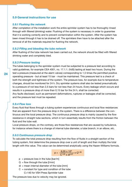
5.9.5 Continuous pressure drop<br />
To calculate the total pressure drop resulting from the flow of fluids in a straight section of the<br />
tubing system, first determine the pressure drop over a unit of length and then multiply the total<br />
length with this value. This value can be determined analytically using the Hazen-Williams formula.<br />
6,05 x 10 5<br />
p = ------------------------- x Q 1,85<br />
C 1,85 x di 4,87<br />
p = pressure loss in the tube [bar/m]<br />
Q = flow through the tube [l/min]<br />
di = mean internal diameter of the tube [mm]<br />
C = constant for type and condition of the tube<br />
C=140 for <strong>VSH</strong> <strong>Press</strong> Sprinkler tube<br />
The pressure loss due to velocity may be ignored.