DIGIMAT Brochure - Figes.com.tr
DIGIMAT Brochure - Figes.com.tr
DIGIMAT Brochure - Figes.com.tr

Create successful ePaper yourself
Turn your PDF publications into a flip-book with our unique Google optimized e-Paper software.
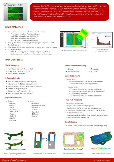
Map is a Shell & 3D mapping software used to <strong>tr</strong>ansfer fiber orientations, residual s<strong>tr</strong>esses,<br />
temperatures and weldlines between dissimilar injection molding and s<strong>tr</strong>uctural FEA<br />
meshes. Map helps assessing the level of difference between the data on the original and<br />
the final mapped solution. Map enables s<strong>tr</strong>uctural engineers to using the optimal mesh<br />
type needed for an accurate and efficient FEA.<br />
NEW IN <s<strong>tr</strong>ong>DIGIMAT</s<strong>tr</strong>ong> 4.1<br />
Enhancement of supported data files and data formats:<br />
- Temperature field from Moldflow midplane<br />
- Nodal fiber orientation from Moldflow 3D<br />
- Nodal fiber orientation from REM3D<br />
- XML file format from Moldflow midplane<br />
Through-the-thickness mapping (1D mapping) of temperature fields<br />
for shell meshes<br />
Computation of a norm of the absolute local error when mapping tensors<br />
GUI improvements:<br />
- 2D plots( Probing, grid, box zoom), histogram capabilities<br />
- Customization of mouse keys for <strong>tr</strong>anslation, rotation and zoom<br />
MAIN CAPABILITIES<br />
Mapping of temperature field on shell element models.<br />
Global error indicator<br />
New histogram plot capability<br />
Shell & 3D Mapping<br />
From Midplane to multi-layered shell<br />
Between Continuum 3D elements<br />
Across the shell thickness<br />
6 Mapping Methods<br />
Node to Node (temperature mapping only)<br />
Integration point, Node to Integration point<br />
Integration point, Node to Node, Integration point<br />
Element to Integration point<br />
Element to Node/Integration point<br />
Node to element (weld line mapping)<br />
Supported File Format<br />
Meshes:<br />
- Abaqus<br />
- ANSYS<br />
- Ideas<br />
- LS-DYNA<br />
- PAM-CRASH<br />
- Pa<strong>tr</strong>an<br />
- RADIOSS<br />
- REM3D<br />
- 3D Timon<br />
Data:<br />
- Moldex3D<br />
- Moldflow Mid-Plane<br />
- Moldflow 3D<br />
- REM3D<br />
- SigmaSoft<br />
- 3D Timon<br />
- <s<strong>tr</strong>ong>DIGIMAT</s<strong>tr</strong>ong><br />
Donor-Receiver Positioning<br />
Scaling<br />
Superpose mesh<br />
Supported Elements<br />
Donor mesh:<br />
- 1 st order te<strong>tr</strong>ahedron or <strong>tr</strong>iangular shell elements<br />
- 1 st order hexahedron and wedge elements<br />
Receiver mesh:<br />
- 1 st order te<strong>tr</strong>ahedron or <strong>tr</strong>iangular shell elements<br />
- 1 st order hexahedron or quadrangular shell elements<br />
- 1 st order wedge elements<br />
- 2 nd order hexahedron and te<strong>tr</strong>ahedron elements<br />
Data Post-Processing<br />
Contour or vector plots<br />
Display tensorial fields using ellipsoids<br />
Synchronized display of donor and receiving meshes<br />
Through the thickness orientation plot for shell elements<br />
Cut plane on 3D meshes<br />
Superposition display of the donor with the receiving meshes<br />
Selective display of element sets<br />
Error Indicators<br />
Translation<br />
Rotation<br />
Global & local error indicators to validate mapping quality<br />
Mapping of midplane fiber orientation tensors<br />
Courtesy of Renault<br />
Partial mapping of 3D fiber orientation tensors<br />
Fibre orientation using the ellipsoid display<br />
Vector plot of fiber orientations on a 3D<br />
The material modeling <s<strong>tr</strong>ong>com</s<strong>tr</strong>ong>pany<br />
www.e-Xs<strong>tr</strong>eam.<s<strong>tr</strong>ong>com</s<strong>tr</strong>ong>