ANSYS Icepak - Figes.com.tr
ANSYS Icepak - Figes.com.tr
ANSYS Icepak - Figes.com.tr

You also want an ePaper? Increase the reach of your titles
YUMPU automatically turns print PDFs into web optimized ePapers that Google loves.
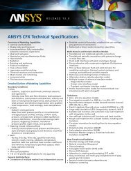
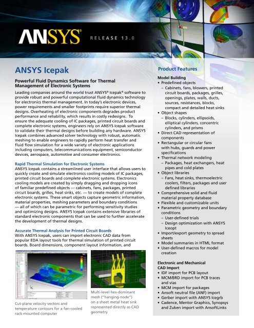
<s<strong>tr</strong>ong>ANSYS</s<strong>tr</strong>ong> <s<strong>tr</strong>ong>Icepak</s<strong>tr</strong>ong>Powerful Fluid Dynamics Software for ThermalManagement of Elec<strong>tr</strong>onic SystemsLeading <s<strong>tr</strong>ong>com</s<strong>tr</strong>ong>panies around the world <strong>tr</strong>ust <s<strong>tr</strong>ong>ANSYS</s<strong>tr</strong>ong> ® <s<strong>tr</strong>ong>Icepak</s<strong>tr</strong>ong> ® software toprovide robust and powerful <s<strong>tr</strong>ong>com</s<strong>tr</strong>ong>putational fluid dynamics technologyfor elec<strong>tr</strong>onics thermal management. In today’s elec<strong>tr</strong>onic devices,power requirements and smaller footprints require superior thermaldesigns. Overheating of elec<strong>tr</strong>onic <s<strong>tr</strong>ong>com</s<strong>tr</strong>ong>ponents degrades productperformance and reliability, which results in costly redesigns. Toensure the adequate cooling of IC packages, printed circuit boards and<s<strong>tr</strong>ong>com</s<strong>tr</strong>ong>plete elec<strong>tr</strong>onic systems, engineers rely on <s<strong>tr</strong>ong>ANSYS</s<strong>tr</strong>ong> <s<strong>tr</strong>ong>Icepak</s<strong>tr</strong>ong> softwareto validate their thermal designs before building any hardware. <s<strong>tr</strong>ong>ANSYS</s<strong>tr</strong>ong><s<strong>tr</strong>ong>Icepak</s<strong>tr</strong>ong> <s<strong>tr</strong>ong>com</s<strong>tr</strong>ong>bines advanced solver technology with robust, automaticmeshing to enable engineers to rapidly perform heat <strong>tr</strong>ansfer andfluid flow simulation for a wide variety of elec<strong>tr</strong>onic applicationsincluding <s<strong>tr</strong>ong>com</s<strong>tr</strong>ong>puters, tele<s<strong>tr</strong>ong>com</s<strong>tr</strong>ong>munications equipment, semiconductordevices, aerospace, automotive and consumer elec<strong>tr</strong>onics.Rapid Thermal Simulation for Elec<strong>tr</strong>onic Systems<s<strong>tr</strong>ong>ANSYS</s<strong>tr</strong>ong> <s<strong>tr</strong>ong>Icepak</s<strong>tr</strong>ong> contains a s<strong>tr</strong>eamlined user interface that allows users toquickly create and simulate elec<strong>tr</strong>onics cooling models of IC packages,printed circuit boards and <s<strong>tr</strong>ong>com</s<strong>tr</strong>ong>plete elec<strong>tr</strong>onic systems. Elec<strong>tr</strong>onicscooling models are created by simply dragging and dropping iconsof familiar predefined objects — cabinets, fans, packages, printedcircuit boards, grilles, heat sinks, etc. — to create models of <s<strong>tr</strong>ong>com</s<strong>tr</strong>ong>pleteelec<strong>tr</strong>onic systems. These smart objects capture geome<strong>tr</strong>ic information,material properties, meshing parameters and boundary conditions— all of which can be parame<strong>tr</strong>ic for performing sensitivity studiesand optimizing designs. <s<strong>tr</strong>ong>ANSYS</s<strong>tr</strong>ong> <s<strong>tr</strong>ong>Icepak</s<strong>tr</strong>ong> contains extensive libraries ofstandard elec<strong>tr</strong>onic <s<strong>tr</strong>ong>com</s<strong>tr</strong>ong>ponents that can be used to further acceleratethe development of thermal designs.Accurate Thermal Analysis for Printed Circuit BoardsWith <s<strong>tr</strong>ong>ANSYS</s<strong>tr</strong>ong> <s<strong>tr</strong>ong>Icepak</s<strong>tr</strong>ong>, users can import elec<strong>tr</strong>onic CAD data frompopular EDA layout tools for thermal simulation of printed circuitboards. Board dimensions, <s<strong>tr</strong>ong>com</s<strong>tr</strong>ong>ponent layout information, andProduct FeaturesModel Building• Predefined objects– Cabinets, fans, blowers, printedcircuit boards, packages, grilles,openings, plates, walls, ducts,sources, resistances, blocks,<s<strong>tr</strong>ong>com</s<strong>tr</strong>ong>pact and detailed heat sinks• Object shapes– Blocks, cylinders, ellipsoids,elliptical cylinders, concen<strong>tr</strong>iccylinders, and prisms• Direct CAD representation of<s<strong>tr</strong>ong>com</s<strong>tr</strong>ong>ponents• Rectangular or circular fanswith hubs, guards and powerspecifications• Thermal network modeling– Packages, heat exchangers, heatpipes and cold plates• Object libraries– Fans, heat sinks, thermoelec<strong>tr</strong>iccoolers, filters, packages and userdefined libraries• Comprehensive solid and fluidmaterial property database• Flexible and customizable units• Parame<strong>tr</strong>ic geome<strong>tr</strong>y and boundaryconditions– User-defined <strong>tr</strong>ials– Design optimization with <s<strong>tr</strong>ong>ANSYS</s<strong>tr</strong>ong>Iceopt• Import/export geome<strong>tr</strong>y to spreadsheets• Model summaries in HTML format• User-defined macros for modelcreationCut-plane velocity vectors andtemperature contours for a fan-cooledrack-mounted <s<strong>tr</strong>ong>com</s<strong>tr</strong>ong>puterMulti-level hex-dominantmesh (“hanging-node”)on a sheet metal heat sinkrepresented directly as CADgeome<strong>tr</strong>yElec<strong>tr</strong>onic and MechanicalCAD Import• IDF import for PCB layout• MCM/BRD import for PCB <strong>tr</strong>acesand vias• MCM import for packages• Ansoft neu<strong>tr</strong>al file (ANF) import• Gerber import with <s<strong>tr</strong>ong>ANSYS</s<strong>tr</strong>ong> Icegrb• Cadence, Mentor Graphics, Synopsysand Zuken import with AnsoftLinks
Product Features• IGES, STEP• <s<strong>tr</strong>ong>ANSYS</s<strong>tr</strong>ong> ® DesignModeler export to<s<strong>tr</strong>ong>ANSYS</s<strong>tr</strong>ong> <s<strong>tr</strong>ong>Icepak</s<strong>tr</strong>ong> objects• Support for <s<strong>tr</strong>ong>ANSYS</s<strong>tr</strong>ong> Geome<strong>tr</strong>y Interfaceswith <s<strong>tr</strong>ong>ANSYS</s<strong>tr</strong>ong> DesignModelerAutomatic Mesh Generation• Automatic hex-dominant meshing for<strong>tr</strong>ue geome<strong>tr</strong>y representation– Automatic multi-level meshing– 2-D and 3-D cut cell techniques– Automatic non-conformal regions– Robust meshing of CAD geome<strong>tr</strong>y• Uns<strong>tr</strong>uctured hexahedral meshing• Cartesian meshing• Non-conformal regions• Embedded non-conformal meshing• Ex<strong>tr</strong>uded meshes for packages andboards• Coarse mesh option for first-pass analysis• Mesh quality evaluation toolsBoundary Conditions• Temperature, heat flux, convective heat<strong>tr</strong>ansfer coefficient, radiation, symme<strong>tr</strong>yand periodic boundary conditions forwalls and surfaces• Inlet and outlet velocity, mass flow rate,outlet static pressure, inlet total pressure,inlet temperature and turbulenceparameters for openings and vents• Profiles of velocity, temperature, heatflux and heat <strong>tr</strong>ansfer coefficients onopenings and walls• Grilles and resistances with automaticloss coefficient based on free area ratio• Fans with options for mass flow rate orfan performance curve• Rotational speed for cylindrical andcircular objects• Recirculating boundary conditions forexternal heat exchangers• Time-dependent and enhancedtemperature-dependent sources• Time-varying ambient temperature• Automatic correlation-based heat<strong>tr</strong>ansfer coefficient boundary conditions• Time-dependent pressure• Elec<strong>tr</strong>ic current and voltage• Power map import from IC package andPCB design tools• Transient boundary condition importfrom spreadsheetselec<strong>tr</strong>onic <strong>tr</strong>ace and via information can all be imported into a thermalsimulation. Using the <strong>tr</strong>ace and via information, a detailed thermalconductivity map of the board can be <s<strong>tr</strong>ong>com</s<strong>tr</strong>ong>puted based on the coppercontent of the board layers. This allows the engineer to accuratelyrepresent the ortho<strong>tr</strong>opic thermal material properties of the board,which provides an increased fidelity in the prediction of the internaltemperatures and <s<strong>tr</strong>ong>com</s<strong>tr</strong>ong>ponent junction temperatures. Resistive heatingin the individual <strong>tr</strong>aces carrying significant current can be modeled tofurther increase the accuracy of simulations.Multi-level hex-dominant mesh(“hanging-node”) of a heat sinkand fan assembly representeddirectly as a CAD geome<strong>tr</strong>yTemperature contours on a 272-pinball grid array (BGA) package on asubs<strong>tr</strong>ateDetailed and Compact Thermal Models for IC Packages<s<strong>tr</strong>ong>ANSYS</s<strong>tr</strong>ong> <s<strong>tr</strong>ong>Icepak</s<strong>tr</strong>ong> includes options for both detailed and <s<strong>tr</strong>ong>com</s<strong>tr</strong>ong>pact thermalmodeling of IC packages. Based on elec<strong>tr</strong>onic CAD data from EDAlayout tools, users can import information such as subs<strong>tr</strong>ate <strong>tr</strong>acesand vias, bond wires, solder bumps, die dimensions and solder ballsinto a detailed thermal model of an IC package. Using the subs<strong>tr</strong>ate<strong>tr</strong>ace and via information, detailed thermal conductivity maps forthe package subs<strong>tr</strong>ate can be developed to accurately represent theortho<strong>tr</strong>opic thermal material properties of the subs<strong>tr</strong>ate. From adetailed package model, <s<strong>tr</strong>ong>ANSYS</s<strong>tr</strong>ong> <s<strong>tr</strong>ong>Icepak</s<strong>tr</strong>ong> contains an automated processfor DELPHI package characterization (JEDEC <s<strong>tr</strong>ong>com</s<strong>tr</strong>ong>pliant). The optimizedDELPHI network model can easily be included in a system-level thermalsimulation, which allows the engineer to accurately predict junctiontemperatures of IC <s<strong>tr</strong>ong>com</s<strong>tr</strong>ong>ponents.Flexible Automatic Meshing Technology<s<strong>tr</strong>ong>ANSYS</s<strong>tr</strong>ong> <s<strong>tr</strong>ong>Icepak</s<strong>tr</strong>ong> contains advanced meshing algorithms to automaticallygenerate high-quality grids that represent the <strong>tr</strong>ue shape of elec<strong>tr</strong>onic<s<strong>tr</strong>ong>com</s<strong>tr</strong>ong>ponents. Options include hex-dominant, uns<strong>tr</strong>uctured hexahedraland Cartesian meshing, which enable the engineer to automaticallygenerate body-fitted meshes with minimal intervention. The user canlocalize the mesh density through nonconformal mesh interfaces,which allows the inclusion of a variety of <s<strong>tr</strong>ong>com</s<strong>tr</strong>ong>ponent scales within thesame elec<strong>tr</strong>onics cooling model. While fully automated, <s<strong>tr</strong>ong>ANSYS</s<strong>tr</strong>ong> <s<strong>tr</strong>ong>Icepak</s<strong>tr</strong>ong>also contains many mesh con<strong>tr</strong>ols that enable the customizationof meshing parameters to refine the mesh and optimize <strong>tr</strong>ade-offsbetween <s<strong>tr</strong>ong>com</s<strong>tr</strong>ong>putational cost and solution accuracy. The meshingflexibility of <s<strong>tr</strong>ong>ANSYS</s<strong>tr</strong>ong> <s<strong>tr</strong>ong>Icepak</s<strong>tr</strong>ong> offers the fastest solution times possiblewithout <s<strong>tr</strong>ong>com</s<strong>tr</strong>ong>promising solution accuracy.
Robust and Rapid Numerical Solutions<s<strong>tr</strong>ong>ANSYS</s<strong>tr</strong>ong> <s<strong>tr</strong>ong>Icepak</s<strong>tr</strong>ong> uses state-of-the-art technology available in the<s<strong>tr</strong>ong>ANSYS</s<strong>tr</strong>ong> ® FLUENT ® <s<strong>tr</strong>ong>com</s<strong>tr</strong>ong>putational fluid dynamics (CFD) solver for thethermal and fluid-flow calculations. <s<strong>tr</strong>ong>ANSYS</s<strong>tr</strong>ong> <s<strong>tr</strong>ong>Icepak</s<strong>tr</strong>ong> solves fluid flowand includes all modes of heat <strong>tr</strong>ansfer - conduction, convectionand radiation - for both steady-state and <strong>tr</strong>ansient thermal-flowsimulations. The solver uses a multi-grid scheme to accelerate solutionconvergence for conjugate heat <strong>tr</strong>ansfer problems. The <s<strong>tr</strong>ong>ANSYS</s<strong>tr</strong>ong> <s<strong>tr</strong>ong>Icepak</s<strong>tr</strong>ong>solver provides <s<strong>tr</strong>ong>com</s<strong>tr</strong>ong>plete mesh flexibility, and allows users to solveeven the most <s<strong>tr</strong>ong>com</s<strong>tr</strong>ong>plex elec<strong>tr</strong>onic assemblies using uns<strong>tr</strong>ucturedmeshes, providing robust and ex<strong>tr</strong>emely fast solution times.Detailed thermal conductivity map for an IC package subs<strong>tr</strong>ate layer<s<strong>tr</strong>ong>com</s<strong>tr</strong>ong>puted based on the elec<strong>tr</strong>onic <strong>tr</strong>ace and via informationResults Visualization and ReportingFor post-processing, <s<strong>tr</strong>ong>ANSYS</s<strong>tr</strong>ong> <s<strong>tr</strong>ong>Icepak</s<strong>tr</strong>ong> contains a full suite of qualitativeand quantitative tools to generate meaningful graphics, animationsand reports. These can be used to easily convey simulation resultsto colleagues and customers. Visualization of velocity vectors,temperature contours, fluid particle <strong>tr</strong>aces, iso-surface displays,cut-planes and XY plots of results data are all available for use ininterpreting the results of elec<strong>tr</strong>onics cooling simulations. Customizedreports, including images, can be automatically created for dis<strong>tr</strong>ibutingresults data, identifying <strong>tr</strong>ends in the simulation, and reporting fanand blower operating points. <s<strong>tr</strong>ong>ANSYS</s<strong>tr</strong>ong> <s<strong>tr</strong>ong>Icepak</s<strong>tr</strong>ong> includes <s<strong>tr</strong>ong>ANSYS</s<strong>tr</strong>ong> CFD-Postsoftware for further post-processing of your results with advancedpost-processing, graphics and animation tools.Interfaces to Elec<strong>tr</strong>ical and Mechanical Simulation<s<strong>tr</strong>ong>ANSYS</s<strong>tr</strong>ong> <s<strong>tr</strong>ong>Icepak</s<strong>tr</strong>ong> provides interfaces to SIwave and <s<strong>tr</strong>ong>ANSYS</s<strong>tr</strong>ong> ®Mechanical products, thus providing access to a full suite of toolsto address elec<strong>tr</strong>ical, thermal and s<strong>tr</strong>uctural simulation requirements.Based on an SIwave analysis, the DC power dis<strong>tr</strong>ibution profilecan be imported into <s<strong>tr</strong>ong>ANSYS</s<strong>tr</strong>ong> <s<strong>tr</strong>ong>Icepak</s<strong>tr</strong>ong> to account for heating due tocopper resistive losses. The coupling between SIwave and <s<strong>tr</strong>ong>ANSYS</s<strong>tr</strong>ong><s<strong>tr</strong>ong>Icepak</s<strong>tr</strong>ong> enables users to predictboth internal temperatures andaccurate <s<strong>tr</strong>ong>com</s<strong>tr</strong>ong>ponent junctiontemperatures for printed circuitboards and packages. FollowingVelocity vectors for a heat sink-fanassembly, fan modeled using movingreference frame (MRF) fan model,image created using <s<strong>tr</strong>ong>ANSYS</s<strong>tr</strong>ong> CFD-PostProduct FeaturesComprehensive Thermal Flow Modeling• Steady-state or <strong>tr</strong>ansient analysis• Laminar or turbulent flows– Laminar regions in turbulent models• Forced, natural and mixed convection• Conduction in solids• Conjugate heat <strong>tr</strong>ansfer• Radiation heat <strong>tr</strong>ansfer– Surface-to-surface radiation– Discrete-ordinates radiation– Ray <strong>tr</strong>acing radiation– Solar loading• Volume<strong>tr</strong>ic resistances and sources forvelocity and energy• Joule heating in <strong>tr</strong>aces and conductors• Thermal network modelingAdvanced Physical Models• Zero-equation turbulence model• Two-equation k-ε turbulence model• RNG k-ε turbulence model• Realizable k-ε turbulence model• Spalart-Allmaras turbulence model• Ideal gas law• Aniso<strong>tr</strong>opic thermal conductivity forsolids• Temperature-dependent materials• Contact resistance models• Non-iso<strong>tr</strong>opic volume<strong>tr</strong>ic flow resistance• Nonlinear fan curves• Moving reference frame (MRF) fan• Automatic radiation view factor<s<strong>tr</strong>ong>com</s<strong>tr</strong>ong>putation• Two-resistor, star and DELPHI networkmodels for IC packagesSolver At<strong>tr</strong>ibutes• <s<strong>tr</strong>ong>ANSYS</s<strong>tr</strong>ong> FLUENT technology– Robust convergence for laminar andturbulent flows• First-order upwind or higher-orderscheme• Automatic under relaxation• Advanced stabilization methods• Variable time stepping for <strong>tr</strong>ansients• Parallel solver available with <s<strong>tr</strong>ong>ANSYS</s<strong>tr</strong>ong> HPC• Batch queuing• Graphical convergence monitoringRELEASE 13.0
Product FeaturesResults Visualization and Reporting• Interactive, object-based visualizationof results• Contour and vector displays, cut planes,particle <strong>tr</strong>aces and iso-surfaces• Point probes with XY plotting• Animation of particle <strong>tr</strong>aces• Animation of vectors, contoursand cut planes• Point objects– Solution convergence monitoring,post-processing, and reports• Report generation– Solution overview– Trials report and plots– Power and temperature limits– Fan and blower operating points• Time history displays• Export results to <s<strong>tr</strong>ong>ANSYS</s<strong>tr</strong>ong> CFD-Post• Export temperature data to <s<strong>tr</strong>ong>ANSYS</s<strong>tr</strong>ong>MechanicalOnline Help and Documentation• Context-sensitive help• Tutorials and validation examplesSupported Hardware*• HP-UX 11i v2 (B.11.23) 64-bit• Linux Redhat (5), Suse Linux ES (10,11)32-bit• Linux Redhat (5), Suse (11) 64-bit• Windows 7, XP, 2008 Server, Vista 32-bit• Windows 7, XP, 2008 Server, 2008 Server(HPC), Vista 64-bitAdditional Modules• <s<strong>tr</strong>ong>ANSYS</s<strong>tr</strong>ong> HPC• <s<strong>tr</strong>ong>ANSYS</s<strong>tr</strong>ong> DesignModeler• <s<strong>tr</strong>ong>ANSYS</s<strong>tr</strong>ong> Geome<strong>tr</strong>y Interfaces• AnsoftLinks• <s<strong>tr</strong>ong>ANSYS</s<strong>tr</strong>ong> Iceopt• <s<strong>tr</strong>ong>ANSYS</s<strong>tr</strong>ong> Icegrb* Refer to www.ansys.<s<strong>tr</strong>ong>com</s<strong>tr</strong>ong> for a current list ofsupported hardware and operating systemsan <s<strong>tr</strong>ong>ANSYS</s<strong>tr</strong>ong> <s<strong>tr</strong>ong>Icepak</s<strong>tr</strong>ong> simulation, a user can export the temperaturesfrom a thermal flow simulation into <s<strong>tr</strong>ong>ANSYS</s<strong>tr</strong>ong> Mechanical using the<s<strong>tr</strong>ong>ANSYS</s<strong>tr</strong>ong> ® Workbench platform. The coupling between <s<strong>tr</strong>ong>ANSYS</s<strong>tr</strong>ong> <s<strong>tr</strong>ong>Icepak</s<strong>tr</strong>ong>and <s<strong>tr</strong>ong>ANSYS</s<strong>tr</strong>ong> Mechanical enables the evaluation of temperatures andresulting thermal s<strong>tr</strong>esses of elec<strong>tr</strong>onic <s<strong>tr</strong>ong>com</s<strong>tr</strong>ong>ponents via an integratedset of software tools.Elec<strong>tr</strong>ic potentialcontours on a printedcircuit board <strong>tr</strong>ace,elec<strong>tr</strong>onic <strong>tr</strong>aceinformation importedfrom elec<strong>tr</strong>onic CADVelocity s<strong>tr</strong>eamlines colored by fanfor a card array in a VME format boxcooled by three axial fans, imagecreated using <s<strong>tr</strong>ong>ANSYS</s<strong>tr</strong>ong> CFD-PostThe <s<strong>tr</strong>ong>ANSYS</s<strong>tr</strong>ong> AdvantageWith the unequalled depth and unparalleled breadth of <s<strong>tr</strong>ong>ANSYS</s<strong>tr</strong>ong>engineering simulation solutions, <s<strong>tr</strong>ong>com</s<strong>tr</strong>ong>panies are <strong>tr</strong>ansforming theirleading-edge design concepts into innovative products and processesthat work. Today, almost all of the top 100 indus<strong>tr</strong>ial <s<strong>tr</strong>ong>com</s<strong>tr</strong>ong>panies on the“FORTUNE Global 500” invest in engineering simulation as a key s<strong>tr</strong>ategyto win in a globally <s<strong>tr</strong>ong>com</s<strong>tr</strong>ong>petitive environment. They choose <s<strong>tr</strong>ong>ANSYS</s<strong>tr</strong>ong>as their simulation partner, deploying the world’s most <s<strong>tr</strong>ong>com</s<strong>tr</strong>ong>prehensivemulti-physics solutions to solve their <s<strong>tr</strong>ong>com</s<strong>tr</strong>ong>plex engineering challenges.The engineered scalability of solutions from <s<strong>tr</strong>ong>ANSYS</s<strong>tr</strong>ong> delivers the flexibilitycustomers need, within an architecture that is adaptable to the processesand design systems of their choice. No wonder the world’s mostsuccessful <s<strong>tr</strong>ong>com</s<strong>tr</strong>ong>panies turn to <s<strong>tr</strong>ong>ANSYS</s<strong>tr</strong>ong> — with a <strong>tr</strong>ack record of 40 years asthe indus<strong>tr</strong>y leader — for the best in engineering simulation.www.ansys.<s<strong>tr</strong>ong>com</s<strong>tr</strong>ong><s<strong>tr</strong>ong>ANSYS</s<strong>tr</strong>ong>, Inc.Southpointe275 Technology DriveCanonsburg, PA 15317U.S.A.724.746.3304ansysinfo@ansys.<s<strong>tr</strong>ong>com</s<strong>tr</strong>ong>Toll Free U.S.A./Canada:1.866.267.9724Toll Free Mexico:001.866.267.9724Europe:44.870.010.4456eu.sales@ansys.<s<strong>tr</strong>ong>com</s<strong>tr</strong>ong><s<strong>tr</strong>ong>ANSYS</s<strong>tr</strong>ong>, <s<strong>tr</strong>ong>ANSYS</s<strong>tr</strong>ong> Workbench, Ansoft, AUTODYN, CFX, FLUENT, and any and all <s<strong>tr</strong>ong>ANSYS</s<strong>tr</strong>ong>, Inc. brand, product,service and feature names, logos and slogans are registered <strong>tr</strong>ademarks or <strong>tr</strong>ademarks of <s<strong>tr</strong>ong>ANSYS</s<strong>tr</strong>ong>, Inc. or itssubsidiaries in the United States or other coun<strong>tr</strong>ies. All other brand, product, service and feature names or<strong>tr</strong>ademarks are the property of their respective owners.© 2010 <s<strong>tr</strong>ong>ANSYS</s<strong>tr</strong>ong>, Inc. All Rights Reserved. Printed in U.S.A. MKT0000498 10-10