Introducing ANSYS Workbench 2.0 (PDF) - Figes.com.tr
Introducing ANSYS Workbench 2.0 (PDF) - Figes.com.tr
Introducing ANSYS Workbench 2.0 (PDF) - Figes.com.tr

You also want an ePaper? Increase the reach of your titles
YUMPU automatically turns print PDFs into web optimized ePapers that Google loves.
1<s<strong>tr</strong>ong>2.0</s<strong>tr</strong>ong>: FRAMEWORK<br />
<s<strong>tr</strong>ong>In<strong>tr</strong>oducing</s<strong>tr</strong>ong><br />
<s<strong>tr</strong>ong>ANSYS</s<strong>tr</strong>ong> <s<strong>tr</strong>ong>Workbench</s<strong>tr</strong>ong> <s<strong>tr</strong>ong>2.0</s<strong>tr</strong>ong><br />
Proven simulation technology is delivered in a <strong>tr</strong>uly<br />
innovative integration framework.<br />
<s<strong>tr</strong>ong>ANSYS</s<strong>tr</strong>ong> 1<s<strong>tr</strong>ong>2.0</s<strong>tr</strong>ong> delivers innovative,<br />
dramatic simulation technology<br />
advances in every major physics<br />
discipline, along with improvements in<br />
<s<strong>tr</strong>ong>com</s<strong>tr</strong>ong>puting speed and enhancements<br />
to enabling technologies such as<br />
geome<strong>tr</strong>y handling, meshing and<br />
post-processing. These advancements<br />
alone represent a major step ahead<br />
on the path forward in Simulation<br />
Driven Product Development. But<br />
<s<strong>tr</strong>ong>ANSYS</s<strong>tr</strong>ong> has reached even further by<br />
delivering all this technology in an<br />
innovative simulation framework,<br />
<s<strong>tr</strong>ong>ANSYS</s<strong>tr</strong>ong> <s<strong>tr</strong>ong>Workbench</s<strong>tr</strong>ong> <s<strong>tr</strong>ong>2.0</s<strong>tr</strong>ong>.<br />
The <s<strong>tr</strong>ong>ANSYS</s<strong>tr</strong>ong> <s<strong>tr</strong>ong>Workbench</s<strong>tr</strong>ong> environment<br />
is the glue that binds the<br />
simulation process; this has not<br />
changed with version <s<strong>tr</strong>ong>2.0</s<strong>tr</strong>ong>. In the original<br />
<s<strong>tr</strong>ong>ANSYS</s<strong>tr</strong>ong> <s<strong>tr</strong>ong>Workbench</s<strong>tr</strong>ong>, the user interacted<br />
with the analysis as a whole using the<br />
platform’s project page: launching the<br />
various applications and <strong>tr</strong>acking the<br />
resulting files employed in the process<br />
of creating an analysis. Tight integration<br />
between the <s<strong>tr</strong>ong>com</s<strong>tr</strong>ong>ponent applications<br />
yielded unprecedented ease of use for<br />
setup and solution of even <s<strong>tr</strong>ong>com</s<strong>tr</strong>ong>plex<br />
multiphysics simulations.<br />
In <s<strong>tr</strong>ong>ANSYS</s<strong>tr</strong>ong> 1<s<strong>tr</strong>ong>2.0</s<strong>tr</strong>ong>, while the core<br />
applications may seem familiar, they<br />
are bound together via the innovative<br />
project page that in<strong>tr</strong>oduces the<br />
concept of the project schematic.<br />
This expands on the project page<br />
concept. Rather than offer a simple<br />
list of files, the project schematic<br />
presents a <s<strong>tr</strong>ong>com</s<strong>tr</strong>ong>prehensive view of<br />
the entire analysis project in flowchart<br />
form in which explicit data<br />
relationships are readily apparent.<br />
Building and interacting with these<br />
flowcharts is s<strong>tr</strong>aightforward. A toolbox<br />
contains a selection of systems that<br />
form the building blocks of the project.<br />
To perform a typical simulation, such<br />
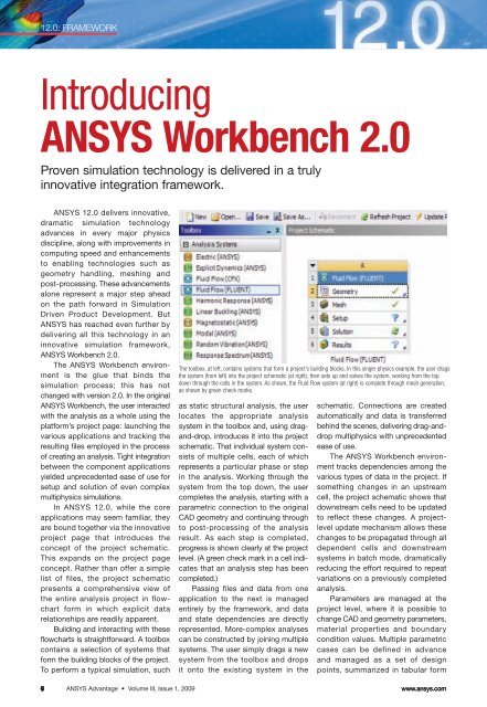
The toolbox, at left, contains systems that form a project’s building blocks. In this single-physics example, the user drags<br />
the system (from left) into the project schematic (at right), then sets up and solves the system, working from the top<br />
down through the cells in the system. As shown, the Fluid Flow system (at right) is <s<strong>tr</strong>ong>com</s<strong>tr</strong>ong>plete through mesh generation,<br />
as shown by green check marks.<br />
as static s<strong>tr</strong>uctural analysis, the user<br />
locates the appropriate analysis<br />
system in the toolbox and, using dragand-drop,<br />
in<strong>tr</strong>oduces it into the project<br />
schematic. That individual system consists<br />
of multiple cells, each of which<br />
represents a particular phase or step<br />
in the analysis. Working through the<br />
system from the top down, the user<br />
<s<strong>tr</strong>ong>com</s<strong>tr</strong>ong>pletes the analysis, starting with a<br />
parame<strong>tr</strong>ic connection to the original<br />
CAD geome<strong>tr</strong>y and continuing through<br />
to post-processing of the analysis<br />
result. As each step is <s<strong>tr</strong>ong>com</s<strong>tr</strong>ong>pleted,<br />
progress is shown clearly at the project<br />
level. (A green check mark in a cell indicates<br />
that an analysis step has been<br />
<s<strong>tr</strong>ong>com</s<strong>tr</strong>ong>pleted.)<br />
Passing files and data from one<br />
application to the next is managed<br />
entirely by the framework, and data<br />
and state dependencies are directly<br />
represented. More-<s<strong>tr</strong>ong>com</s<strong>tr</strong>ong>plex analyses<br />
can be cons<strong>tr</strong>ucted by joining multiple<br />
systems. The user simply drags a new<br />
system from the toolbox and drops<br />
it onto the existing system in the<br />
schematic. Connections are created<br />
automatically and data is <strong>tr</strong>ansferred<br />
behind the scenes, delivering drag-anddrop<br />
multiphysics with unprecedented<br />
ease of use.<br />
The <s<strong>tr</strong>ong>ANSYS</s<strong>tr</strong>ong> <s<strong>tr</strong>ong>Workbench</s<strong>tr</strong>ong> environment<br />
<strong>tr</strong>acks dependencies among the<br />
various types of data in the project. If<br />
something changes in an ups<strong>tr</strong>eam<br />
cell, the project schematic shows that<br />
downs<strong>tr</strong>eam cells need to be updated<br />
to reflect these changes. A projectlevel<br />
update mechanism allows these<br />
changes to be propagated through all<br />
dependent cells and downs<strong>tr</strong>eam<br />
systems in batch mode, dramatically<br />
reducing the effort required to repeat<br />
variations on a previously <s<strong>tr</strong>ong>com</s<strong>tr</strong>ong>pleted<br />
analysis.<br />
Parameters are managed at the<br />
project level, where it is possible to<br />
change CAD and geome<strong>tr</strong>y parameters,<br />
material properties and boundary<br />
condition values. Multiple parame<strong>tr</strong>ic<br />
cases can be defined in advance<br />
and managed as a set of design<br />
points, summarized in tabular form<br />
6<br />
<s<strong>tr</strong>ong>ANSYS</s<strong>tr</strong>ong> Advantage • Volume III, Issue 1, 2009<br />
www.ansys.<s<strong>tr</strong>ong>com</s<strong>tr</strong>ong>
1<s<strong>tr</strong>ong>2.0</s<strong>tr</strong>ong>: FRAMEWORK<br />
on the <s<strong>tr</strong>ong>ANSYS</s<strong>tr</strong>ong> <s<strong>tr</strong>ong>Workbench</s<strong>tr</strong>ong> project page.<br />
Design Exploration systems can be<br />
connected to these same project-level<br />
parameters to drive automated design<br />
investigations, such as Design of Experiments,<br />
goal-driven optimization or Design<br />
for Six Sigma.<br />
In addition to serving as a framework<br />
for the integration of existing applications,<br />
the <s<strong>tr</strong>ong>ANSYS</s<strong>tr</strong>ong> <s<strong>tr</strong>ong>Workbench</s<strong>tr</strong>ong> <s<strong>tr</strong>ong>2.0</s<strong>tr</strong>ong> platform also<br />
serves as an application development<br />
framework and will ultimately provide<br />
project-wide scripting, reporting, a user<br />
interface (UI) toolkit and standard data<br />
interfaces. These capabilities will emerge<br />
over this and subsequent releases. At<br />
<s<strong>tr</strong>ong>ANSYS</s<strong>tr</strong>ong> 1<s<strong>tr</strong>ong>2.0</s<strong>tr</strong>ong>, Engineering Data and<br />
<s<strong>tr</strong>ong>ANSYS</s<strong>tr</strong>ong> DesignXplorer are no longer<br />
independent applications: They have been<br />
re-engineered using the UI toolkit and<br />
integrated within the <s<strong>tr</strong>ong>ANSYS</s<strong>tr</strong>ong> <s<strong>tr</strong>ong>Workbench</s<strong>tr</strong>ong><br />
project window.<br />
Beyond managing individual simulation<br />
projects, <s<strong>tr</strong>ong>ANSYS</s<strong>tr</strong>ong> <s<strong>tr</strong>ong>Workbench</s<strong>tr</strong>ong><br />
interfaces with the <s<strong>tr</strong>ong>ANSYS</s<strong>tr</strong>ong> Engineering<br />
Knowledge Manager (EKM) product<br />
for simulation process and data<br />
management. At <s<strong>tr</strong>ong>ANSYS</s<strong>tr</strong>ong> 1<s<strong>tr</strong>ong>2.0</s<strong>tr</strong>ong>, <s<strong>tr</strong>ong>ANSYS</s<strong>tr</strong>ong><br />
<s<strong>tr</strong>ong>Workbench</s<strong>tr</strong>ong> includes the single-user<br />
configuration of <s<strong>tr</strong>ong>ANSYS</s<strong>tr</strong>ong> EKM, called<br />
<s<strong>tr</strong>ong>ANSYS</s<strong>tr</strong>ong> EKM Desktop. (See sidebar.)<br />
<s<strong>tr</strong>ong>ANSYS</s<strong>tr</strong>ong> <s<strong>tr</strong>ong>Workbench</s<strong>tr</strong>ong> <s<strong>tr</strong>ong>2.0</s<strong>tr</strong>ong> represents a<br />
sizable step forward in engineering simulation.<br />
Within this innovative software<br />
framework, analysts can leverage a<br />
<s<strong>tr</strong>ong>com</s<strong>tr</strong>ong>plete range of proven simulation<br />
technology, including <s<strong>tr</strong>ong>com</s<strong>tr</strong>ong>mon tools for<br />
CAD integration, geome<strong>tr</strong>y repair and<br />
meshing. A novel project schematic<br />
concept guides users through <s<strong>tr</strong>ong>com</s<strong>tr</strong>ong>plex<br />
analyses, illus<strong>tr</strong>ating explicit data<br />
relationships and capturing the process<br />
for automating subsequent analyses.<br />
Meanwhile, its parame<strong>tr</strong>ic and persistent<br />
modeling environment in conjunction<br />
with integral tools for design optimization<br />
and statistical studies enable engineers<br />
to arrive at the best design faster.<br />
Looking beyond <s<strong>tr</strong>ong>ANSYS</s<strong>tr</strong>ong> 1<s<strong>tr</strong>ong>2.0</s<strong>tr</strong>ong>, the<br />
<s<strong>tr</strong>ong>ANSYS</s<strong>tr</strong>ong> <s<strong>tr</strong>ong>Workbench</s<strong>tr</strong>ong> platform will be<br />
further refined: The aim is to deliver a<br />
<s<strong>tr</strong>ong>com</s<strong>tr</strong>ong>prehensive set of simulation technology<br />
in an open, adaptive software<br />
architecture that allows for pervasive<br />
customization and the integration of<br />
third-party applications. ■<br />
Managing Simulation Data<br />
With the ever-increasing use of simulation, keeping <strong>tr</strong>ack of the<br />
expanding volume of simulation data be<s<strong>tr</strong>ong>com</s<strong>tr</strong>ong>es more and more difficult.<br />
The need to be able to quickly locate information for reuse is paramount to<br />
increasing productivity and reducing development costs.<br />
<s<strong>tr</strong>ong>ANSYS</s<strong>tr</strong>ong> EKM Desktop is a new tool, integrated in the <s<strong>tr</strong>ong>ANSYS</s<strong>tr</strong>ong><br />
<s<strong>tr</strong>ong>Workbench</s<strong>tr</strong>ong> environment, that facilitates managing simulation data from<br />
multiple projects. <s<strong>tr</strong>ong>ANSYS</s<strong>tr</strong>ong> EKM Desktop is a single-user configuration<br />
of EKM that allows users to add files from any project to a local virtual<br />
repository. Simulation properties and other metadata are automatically<br />
ex<strong>tr</strong>acted (or created) from files when added, and users can tag files with<br />
unique identifiers at any time. These at<strong>tr</strong>ibutes can all be used to search<br />
and re<strong>tr</strong>ieve files based on keywords or <s<strong>tr</strong>ong>com</s<strong>tr</strong>ong>plex search criteria. Reports<br />
can be easily generated to allow efficient side-by-side <s<strong>tr</strong>ong>com</s<strong>tr</strong>ong>parison of the<br />
at<strong>tr</strong>ibutes of related analyses. Search queries and reports can be saved for<br />
later re-use. Files that are re<strong>tr</strong>ieved can be directly launched in their associated<br />
simulation application from within the <s<strong>tr</strong>ong>ANSYS</s<strong>tr</strong>ong> EKM Desktop tool.<br />
More-<s<strong>tr</strong>ong>com</s<strong>tr</strong>ong>plex analyses involving multiple physics can be built up by connecting systems. Data dependencies are<br />
indicated clearly as connections. State icons at the right of each cell indicate whether cells are up to date, require user<br />
input or need to be updated — for example, whether they are just meshed or fully solved.<br />
Judd Kaiser, Shantanu Bhide, Scott Gilmore and Todd<br />
McDevitt of <s<strong>tr</strong>ong>ANSYS</s<strong>tr</strong>ong>, Inc. con<strong>tr</strong>ibuted to this article.<br />
Two analyses from the schematics shown in the previous figure are shown here in the mechanical simulation application.<br />
Launched from the schematic, individual applications may be familiar to existing users.<br />
www.ansys.<s<strong>tr</strong>ong>com</s<strong>tr</strong>ong> <s<strong>tr</strong>ong>ANSYS</s<strong>tr</strong>ong> Advantage • Volume III, Issue 1, 2009 7