FLEXpower ONE Installation Manual - OutBack Power Systems
FLEXpower ONE Installation Manual - OutBack Power Systems
FLEXpower ONE Installation Manual - OutBack Power Systems

Create successful ePaper yourself
Turn your PDF publications into a flip-book with our unique Google optimized e-Paper software.
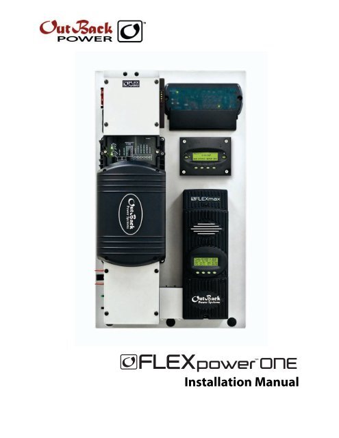
power <strong>ONE</strong><br />
T M<br />
<strong>Installation</strong> <strong>Manual</strong>
About <strong>OutBack</strong> <strong>Power</strong> <strong>Systems</strong><br />
<strong>OutBack</strong> <strong>Power</strong> <strong>Systems</strong> is a leader in advanced energy conversion technology. Our products include<br />
true sine wave inverter/chargers, maximum power point charge controllers, system communication<br />
components, as well as breaker panels, breakers, accessories, and assembled systems.<br />
Contact Information<br />
Telephone:<br />
Address:<br />
E-mail:<br />
Web Site:<br />
Disclaimer<br />
+1.360.435.6030 (North America)<br />
+1.360.618.4363 (Technical Support)<br />
+1.360.435.6019 (Fax)<br />
North America<br />
19009 62nd Avenue NE<br />
Arlington, WA USA<br />
Support@outbackpower.com<br />
www.outbackpower.com<br />
+34.93.654.9568 (Barcelona, Spain)<br />
UNLESS SPECIFICALLY AGREED TO IN WRITING, OUTBACK POWER SYSTEMS:<br />
(a) MAKES NO WARRANTY AS TO THE ACCURACY, SUFFICIENCY OR SUITABILITY OF ANY TECHNICAL<br />
OR OTHER INFORMATION PROVIDED IN ITS MANUALS OR OTHER DOCUMENTATION.<br />
(b) ASSUMES NO RESPONSIBILITY OR LIABILITY FOR LOSS OR DAMAGE, WHETHER DIRECT, INDIRECT,<br />
CONSEQUENTIAL OR INCIDENTAL, WHICH MIGHT ARISE OUT OF THE USE OF SUCH INFORMATION. THE<br />
USE OF ANY SUCH INFORMATION WILL BE ENTIRELY AT THE USER’S RISK.<br />
Warranty Summary<br />
<strong>OutBack</strong> <strong>Power</strong> <strong>Systems</strong> Inc. warrants that the products it manufactures will be free from defects in<br />
materials and workmanship for a period of five (5) years subject to the conditions set forth in the<br />
warranty detail found inside the back cover of this manual.<br />
<strong>OutBack</strong> <strong>Power</strong> <strong>Systems</strong> cannot be responsible for system failure, damages, or injury resulting from<br />
improper installation of their products.<br />
Notice of Copyright<br />
<strong>FLEXpower</strong> <strong>ONE</strong> <strong>Installation</strong> <strong>Manual</strong> ©October 2009 by <strong>OutBack</strong> <strong>Power</strong> <strong>Systems</strong>. All Rights Reserved.<br />
Trademarks<br />
<strong>FLEXpower</strong> <strong>ONE</strong> is a registered trademark of <strong>OutBack</strong> <strong>Power</strong> <strong>Systems</strong>. <strong>OutBack</strong> <strong>Power</strong> is a registered<br />
trademark of <strong>OutBack</strong> <strong>Power</strong> <strong>Systems</strong>.<br />
Date and Revision<br />
October 2009, Revision A<br />
Part Number<br />
900-0095-01-00 Rev A
Important Safety Instructions<br />
READ AND SAVE THESE INSTRUCTIONS!<br />
This manual contains important safety instructions for the <strong>FLEXpower</strong> <strong>ONE</strong>. Read all instructions and<br />
cautionary markings on the <strong>FLEXpower</strong> <strong>ONE</strong> and on any accessories or additional equipment included<br />
in the installation. Failure to adhere to these instructions could result in severe shock or possible<br />
electrocution. Exercise extreme caution at all times to prevent accidents.<br />
Symbols Used<br />
Symbol<br />
Description<br />
Ground<br />
AC Current<br />
DC Current<br />
∅<br />
Single-Phase<br />
Sine Wave<br />
WARNING: Hazard to Human Life<br />
This type of notation indicates that the hazard could be harmful to human life.<br />
CAUTION: Hazard to Equipment<br />
This type of notation indicates that the hazard may cause damage to<br />
the equipment.<br />
Audience<br />
IMPORTANT:<br />
This type of notation indicates that the information provided is important to<br />
the installation, operation and/or maintenance of the equipment. Failure to<br />
follow the recommendations in such a notation could result in voiding the<br />
equipment warranty.<br />
These instructions are for use by qualified personnel who meet all local and governmental code<br />
requirements for licensing and training for the installation of electrical power systems with AC and DC<br />
voltage up to 240 Vac and 150 Vdc.<br />
900-0095-01-00 Rev A 1
Definitions<br />
‣ Off-Grid – Utility Grid <strong>Power</strong> is not available for use.<br />
Important Safety Instructions<br />
‣ On-Grid – Utility Grid power is available for use. Does not imply the ability to sell power back to the<br />
utility grid.<br />
‣ Grid-tie, Grid-interactive, Grid-intertie – Utility Grid <strong>Power</strong> is available for use and the system is<br />
capable of returning (selling) electricity back to the utility grid.<br />
Table 1<br />
Acronym<br />
AC<br />
ANSI<br />
DC<br />
FCC<br />
GND<br />
IEEE<br />
N<br />
NEC<br />
NFPA<br />
OSHA<br />
PV<br />
RE<br />
UL<br />
Acronyms<br />
Definition<br />
Alternating Current<br />
American National Standards Institute<br />
Direct Current<br />
Federal Communications Commission (North America)<br />
Ground<br />
Institute of Electrical and Electronics Engineers<br />
AC Neutral<br />
National Electric Code (North America)<br />
National Fire Protection Association<br />
Occupational Safety and Health Association<br />
Photovoltaic<br />
Renewable Energy<br />
Underwriters Laboratory<br />
General Safety<br />
WARNING: Limitations on Use<br />
This equipment is NOT intended for use with life support equipment or other<br />
medical equipment or devices.<br />
CAUTION: Equipment Damage<br />
Only use components or accessories recommended or sold by <strong>OutBack</strong> <strong>Power</strong><br />
<strong>Systems</strong> or its authorized agents.<br />
IMPORTANT:<br />
Do not attempt to install this equipment if it appears to be damaged in any<br />
way. See the Troubleshooting Section for instructions on how to return the<br />
equipment if you know, or suspect, it is damaged.<br />
2 900-0095-01-00 Rev A
Important Safety Instructions<br />
Personal Safety<br />
WARNING: Personal Injury<br />
‣ This equipment weighs approximately 98 lbs (44.5 kg). Use safe lifting<br />
techniques when lifting this equipment as prescribed by the Occupational<br />
Safety and Health Association (OSHA) or other local codes.<br />
‣ Use standard safety equipment such as safety glasses, ear protection, steeltoed<br />
safety boots, safety hard hats, etc. as prescribed by the Occupational<br />
Safety and Health Association (or other local codes) when working on this<br />
equipment.<br />
‣ Use standard safety practices when working with electrical equipment<br />
(e.g., remove all jewelry, use insulated tools, wear cotton clothing, etc.)<br />
‣ Never work alone when installing or servicing this equipment. Have<br />
someone nearby that can come to your aid if necessary.<br />
<strong>FLEXpower</strong> <strong>ONE</strong> System Safety<br />
WARNING: Lethal Voltage<br />
‣ Review the system configuration to identify all possible sources of energy.<br />
Ensure ALL sources of power are disconnected before performing any<br />
installation or maintenance on this equipment. Confirm that the terminals<br />
are de-energized using a validated voltmeter (rated for a minimum<br />
1000 Vac and 1000 Vdc) to verify the de-energized condition.<br />
‣ Do not perform any servicing other than that specified in the installation<br />
instructions unless qualified to do so or as instructed to do so by <strong>OutBack</strong><br />
<strong>Power</strong> <strong>Systems</strong> Technical Support personnel.<br />
WARNING: Burn Hazard<br />
Internal parts can become hot during operation. Do not remove the cover<br />
during operation or touch any internal parts. Be sure to allow them sufficient<br />
time to cool down before attempting to perform any maintenance.<br />
WARNING: Fire Hazard<br />
‣ In residential installations: check for multi-wire branch circuit wiring at the<br />
location for the installation. A possible fire hazard can exist if 120 Vac only<br />
sources (such as inverters and generators) are wired incorrectly into<br />
120/240 Vac panels containing multi-wire branch circuits. Consult the local<br />
electric code for assistance.<br />
‣ Do not place combustible or flammable materials within 12 feet (3.7 m) of<br />
the equipment.<br />
‣ Use only the recommended cable sizes (or greater) for AC and DC<br />
conductors in compliance with local codes. Ensure all conductors and<br />
connections are in good condition. Do not operate the unit with damaged<br />
or substandard cabling.<br />
900-0095-01-00 Rev A 3
Important Safety Instructions<br />
CAUTION: Equipment Damage<br />
‣ When connecting cables from the inverter to the battery terminals, ensure<br />
the proper polarity is observed. Connecting the cables incorrectly can<br />
damage or destroy the equipment.<br />
‣ Thoroughly inspect the equipment prior to energizing. Verify that no tools<br />
or equipment have been inadvertently left behind.<br />
‣ Ensure clearance requirements are strictly enforced and that all vents are<br />
clear of obstructions that can prevent proper air flow around or through<br />
the unit.<br />
‣ Sensitive electronics inside the equipment can be destroyed by static<br />
electricity. Be sure to discharge any static electricity built up before<br />
touching the equipment and wear appropriate protective gear.<br />
PV Safety<br />
WARNING: Shock Hazard<br />
Photovoltaic (PV) arrays can be energized with minimal ambient light available.<br />
Therefore to ensure a safe disconnect from the system, be sure to install a PV<br />
disconnect, breaker, or accessible fuse box (depending on local code<br />
requirements).<br />
CAUTION: Equipment Damage<br />
PV Arrays must be wired with correct polarity (positive-to-positive, negative-tonegative).<br />
Connecting the cables incorrectly can damage or destroy the<br />
equipment.<br />
Battery Safety<br />
WARNING: Electrocution Hazard<br />
‣ Use the battery types recommended by <strong>OutBack</strong> <strong>Power</strong> <strong>Systems</strong>. Follow<br />
the battery manufacturer’s recommendations for installation and<br />
maintenance.<br />
‣ Ensure clearance requirements are strictly enforced around batteries.<br />
‣ Ensure the area around the batteries is well ventilated and clean of debris.<br />
‣ Always use insulated tools. Avoid dropping tools onto batteries or other<br />
electrical parts.<br />
‣ Keep plenty of fresh water and soap nearby in case battery acid contacts<br />
skin, clothing, or eyes.<br />
‣ If you need to remove a battery, always remove the ground terminal from<br />
the battery first. Make sure all accessories are turned off so you don’t cause<br />
a spark.<br />
‣ If a remote or automatic generator control system is used, disable the<br />
automatic starting circuit and/or disconnect the generator from its starting<br />
battery while performing maintenance to prevent accidental starting.<br />
4 900-0095-01-00 Rev A
Important Safety Instructions<br />
WARNING: Fire or Burn Hazard<br />
‣ Ensure the cables are properly sized. Failure to size the cables properly can<br />
result in a Fire Hazard.<br />
‣ Wear complete eye protection and clothing protection when working with<br />
batteries. Avoid touching your eyes while working near batteries.<br />
‣ If battery acid contacts skin or clothing, wash immediately with soap and<br />
water. If acid enters the eye, immediately flood it with running cold water<br />
for at least 20 minutes and get medical attention immediately.<br />
‣ Never smoke or allow a spark or flame near the batteries.<br />
‣ Keep plenty of fresh water and soap nearby in case battery acid contacts<br />
skin, clothing, or eyes.<br />
WARNING: Explosion Hazard<br />
Never charge a frozen battery. A flooded battery discharged to 40% SOC (stateof-charge)<br />
can freeze at or below -8.9° C (16° F).<br />
CAUTION: Equipment Damage<br />
When connecting cables from the DC input breaker to the battery terminals,<br />
ensure proper polarity is observed (positive-to-positive, negative-to-negative).<br />
Connecting the cables incorrectly can damage or destroy the equipment.<br />
IMPORTANT:<br />
Baking Soda neutralizes lead-acid battery electrolyte.<br />
Vinegar neutralizes NiCad and NiFe battery electrolyte.<br />
Have a supply of either substance readily available if using these types<br />
of batteries.<br />
Regulatory References<br />
‣ National Electric Code (NEC) Article 690, (current edition)<br />
‣ Canadian Electrical Code, Part I (CSA 107.1)<br />
‣ UL 1741-2005 Static Inverter and Charge Controllers for Use in Photovoltaic <strong>Power</strong> <strong>Systems</strong><br />
‣ American National Standards Institute/National Fire Protection Agency (ANSI/NFPA) 70<br />
Recycling Information<br />
IMPORTANT: Recycle Electronics and Batteries<br />
Batteries are considered hazardous waste and must be recycled according to<br />
local jurisdiction. Inverters and other electronics contain metals and plastics<br />
that can (and should) be recycled. The following are some websites and phone<br />
numbers that provide information and “how” and “where” to recycle batteries<br />
and other electronic equipment.<br />
<strong>OutBack</strong> <strong>Power</strong> <strong>Systems</strong> strongly encourages you to learn about recycling and<br />
to dispose of recyclable items accordingly. The Earth, and <strong>OutBack</strong> <strong>Power</strong><br />
<strong>Systems</strong>, thanks you for that effort.<br />
900-0095-01-00 Rev A 5
Earth 911<br />
Web site: www.Earth911.com<br />
Address: 14646 N. Kierland Blvd., Suite 100<br />
Scottsdale, AZ 85254<br />
Phone: +1.480.337.3025 (direct)<br />
Environmental Protection Agency, USA<br />
Important Safety Instructions<br />
Web site: www.epa.gov/recyclecity/<br />
Phone: +1.415.947.8000<br />
(Monday –Friday 8:00 AM to 12:00 PM and 1:00 PM to 4:00 PM PST)<br />
Email: r9.recyclecity@epa.gov<br />
Keep America Beautiful, USA<br />
Web site:<br />
Address:<br />
www.kab.org/<br />
1010 Washington Boulevard<br />
Stamford, CT 06901<br />
+1.203.659.3000 (Main number)<br />
Phone:<br />
Fax: +1.203.659.3001<br />
Email: info@kab.org<br />
Office of Waste Management, Canada<br />
Address:<br />
Office of Waste Management<br />
Conservation and Protection<br />
Environment Canada<br />
Ottawa, Ontaro K1A 0H3<br />
Phone: +1. 819.997.2800<br />
Web site: http://www.portaec.net/library/recycling/recycling_in_canada.html<br />
National Institute of Recyclers, Mexico<br />
Web site: http://www.inare.org.mx/<br />
Email: a57841279@prodigy.net.mx, margarita@inare.org.mx<br />
Phone: 55.57.85.9160<br />
Fax: 55.57.84.1279<br />
EuroRecycle.net<br />
The following website provides general information about Recycling in Europe. It also provides a list<br />
of companies and organizations that provide recycling information or assistance.<br />
Web site:<br />
E-mail:<br />
http://euro.recycle.net/assn/index.html<br />
http://euro.recycle.net/cgi-bin/feedback1.cgi?w=27<br />
(This is an online form providing a means to contact the owners of the website.)<br />
6 900-0095-01-00 Rev A
Table of Contents<br />
Important Safety Instructions ...................................................................1<br />
Symbols Used ........................................................................................................................................................................1<br />
Audience .................................................................................................................................................................................1<br />
Definitions...............................................................................................................................................................................2<br />
General Safety .......................................................................................................................................................................2<br />
Personal Safety......................................................................................................................................................................3<br />
<strong>FLEXpower</strong> <strong>ONE</strong> System Safety.......................................................................................................................................3<br />
PV Safety..................................................................................................................................................................................4<br />
Battery Safety.........................................................................................................................................................................4<br />
Regulatory References........................................................................................................................................................5<br />
Recycling Information ........................................................................................................................................................5<br />
Earth 911 .............................................................................................................................................................................................6<br />
Environmental Protection Agency, USA...................................................................................................................................6<br />
Keep America Beautiful, USA .......................................................................................................................................................6<br />
Office of Waste Management, Canada .....................................................................................................................................6<br />
National Institute of Recyclers, Mexico.....................................................................................................................................6<br />
EuroRecycle.net ................................................................................................................................................................................6<br />
Introduction.............................................................................................11<br />
Components ....................................................................................................................................................................... 12<br />
Applications ........................................................................................................................................................................ 13<br />
On-Grid Applications ....................................................................................................................................................................13<br />
Off-Grid Applications ....................................................................................................................................................................14<br />
Grid-Interactive Applications .....................................................................................................................................................14<br />
PV Array Planning ..........................................................................................................................................................................15<br />
Battery Bank Planning ..................................................................................................................................................................15<br />
Generator Requirements ................................................................................................................................................ 16<br />
Preparation.......................................................................................................................................................................... 17<br />
Tools Required ................................................................................................................................................................................17<br />
Materials Required.........................................................................................................................................................................17<br />
Accessories.......................................................................................................................................................................................17<br />
Location.............................................................................................................................................................................................17<br />
Environmental.................................................................................................................................................................................17<br />
Clearance and Access Requirements ......................................................................................................................... 18<br />
Dimensions.......................................................................................................................................................................... 19<br />
Conduit and Knockout Preparation............................................................................................................................ 20<br />
Mounting.............................................................................................................................................................................. 21<br />
Removing the Covers....................................................................................................................................................... 24<br />
Accessing the Wiring Compartments ........................................................................................................................ 25<br />
Wiring .................................................................................................................................................................................... 26<br />
Grounding ........................................................................................................................................................................................26<br />
DC Connections..............................................................................................................................................................................27<br />
900-0095-01-00 Rev A 7
Table of Contents<br />
AC Connections ..............................................................................................................................................................................31<br />
Functional Test/Commissioning.................................................................................................................................. 33<br />
Pre-startup Procedures ................................................................................................................................................................33<br />
Energize/Startup ............................................................................................................................................................................33<br />
Reassembling the Enclosures ....................................................................................................................................... 35<br />
Operation.................................................................................................39<br />
Setting Basic Parameters ................................................................................................................................................ 39<br />
MATE2 Settings...............................................................................................................................................................................39<br />
Charger Settings.............................................................................................................................................................................39<br />
Setting Time, Date & Display on the MATE2 .........................................................................................................................40<br />
Selecting the AC Source and AC Input Limit on the Inverter ..........................................................................................42<br />
Accessing the Advanced Menu.................................................................................................................................................43<br />
Setting Battery Amp-Hours and Return Amps using the FLEXnet DC Monitor ........................................................44<br />
Setting Charging Parameters.....................................................................................................................................................45<br />
De-energize/Shutdown ...............................................................................................................................................................46<br />
Specifications...........................................................................................49<br />
Feature Matrix .................................................................................................................................................................... 49<br />
Electrical Specifications, 120 Vac/60 Hz Models .................................................................................................... 50<br />
Mechanical Specifications, 120 Vac/60 Hz Models................................................................................................ 50<br />
Electrical Specifications, 230 Vac/50 Hz Models .................................................................................................... 51<br />
Mechanical Specifications, 230 Vac/50 Hz Models................................................................................................ 51<br />
Surge Protector .................................................................................................................................................................. 52<br />
LEDs ....................................................................................................................................................................................................52<br />
Renewable Energy Input & Storage............................................................................................................................ 53<br />
PV Sizing............................................................................................................................................................................................53<br />
Battery Bank Sizing........................................................................................................................................................................53<br />
Amp-Hour Requirements ............................................................................................................................................................53<br />
Wiring Configurations .............................................................................59<br />
<strong>FLEXpower</strong> <strong>ONE</strong> with FLEXnet DC Monitor and GFDI.......................................................................................... 61<br />
<strong>FLEXpower</strong> <strong>ONE</strong> with FLEXnet DC Monitor Only (no GFDI)............................................................................... 62<br />
<strong>FLEXpower</strong> <strong>ONE</strong> with GFDI Only (no FLEXnet DC Monitor)............................................................................... 63<br />
<strong>FLEXpower</strong> <strong>ONE</strong> (no FLEXnet DC Monitor or GFDI) .............................................................................................. 64<br />
Warranty ..................................................................................................65<br />
How to Arrange for Warranty Service ........................................................................................................................ 66<br />
Return Material Authorization (RMA)......................................................................................................................................66<br />
Returning Product to <strong>OutBack</strong> ..................................................................................................................................................66<br />
Index ........................................................................................................67<br />
8 900-0095-01-00 Rev A
Table of Contents<br />
List of Tables<br />
Table 1 Acronyms.............................................................................................................................................................................. 2<br />
Table 2 Basic Components of a <strong>FLEXpower</strong> <strong>ONE</strong> System..................................................................................................12<br />
Table 3 Ground Conductor Size and Torque Requirements.............................................................................................26<br />
Table 4 DC Conductor Size and Torque Requirements......................................................................................................27<br />
Table 5 AC Conductor Size and Torque Requirements ......................................................................................................31<br />
Table 6 Feature Matrix...................................................................................................................................................................49<br />
Table 7 Worksheet for Determining Average Daily Load in Amp-hours ............................................................56<br />
Table 8 Worksheet for Determining Battery Bank Size .................................................................................................57<br />
900-0095-01-00 Rev A 9
Table of Contents<br />
List of Figures<br />
Figure 1 <strong>FLEXpower</strong> <strong>ONE</strong> System Overview ............................................................................................................................11<br />
Figure 2 Basic Components of a <strong>FLEXpower</strong> <strong>ONE</strong> System..................................................................................................12<br />
Figure 3 On-Grid Applications (Example) .................................................................................................................................13<br />
Figure 4 Off-Grid Applications (Example).................................................................................................................................14<br />
Figure 5 Grid-Interactive Applications (Example)..................................................................................................................14<br />
Figure 6 Clearance and Access Requirements ........................................................................................................................18<br />
Figure 7 Dimensions ........................................................................................................................................................................19<br />
Figure 8 Conduit and Knockout Preparation...........................................................................................................................20<br />
Figure 9 Installing the Mounting Bracket .................................................................................................................................22<br />
Figure 10 Attaching the Mounting Plate to the Mounting Bracket ...................................................................................23<br />
Figure 11 Removing the Covers .....................................................................................................................................................24<br />
Figure 12 Wiring and Breaker Compartment.............................................................................................................................25<br />
Figure 13<br />
Figure 14<br />
Ground Connections ......................................................................................................................................................27<br />
Battery Connections with the FLEXnet DC Monitor.............................................................................................28<br />
Figure 15 Battery Connections without the FLEXnet DC.......................................................................................................29<br />
Figure 16 PV Connections with a FLEXnet DC Monitor..........................................................................................................30<br />
Figure 17 AC IN Connections...........................................................................................................................................................31<br />
Figure 18 AC OUT Connections ......................................................................................................................................................32<br />
Figure 19 Energize Procedures.......................................................................................................................................................33<br />
Figure 20 Functional Test Procedures for Initial Startup........................................................................................................34<br />
Figure 21 Replacing the Raceway and FLEXmax 80 Front Cover........................................................................................35<br />
Figure 22 Replacing the Inverter’s AC Terminal Access Cover.............................................................................................35<br />
Figure 23 Replacing the AC Enclosure Front Cover.................................................................................................................36<br />
Figure 24 Replacing the AC Enclosure Top Cover....................................................................................................................36<br />
Figure 25 Replacing the DC Enclosure Front Cover.................................................................................................................37<br />
Figure 26 Replacing the DC Cover.................................................................................................................................................37<br />
Figure 27 MATE2 Setup Screen (Page 1) .....................................................................................................................................40<br />
Figure 28 MATE2 Setup Screen (Page 2 and 3) .........................................................................................................................41<br />
Figure 29 Inverter Setup Screen – Selecting AC Source.........................................................................................................42<br />
Figure 30 Accessing the Advanced Menus.................................................................................................................................43<br />
Figure 31 Setting Battery Amp-hours and Return Amps .......................................................................................................44<br />
Figure 32 Setting Input Source and Current Limit ...................................................................................................................45<br />
Figure 33 Shutdown Procedures....................................................................................................................................................46<br />
Figure 34<br />
Figure 35<br />
Functional Test Procedures to Confirm the Unit is De-energized...................................................................47<br />
<strong>FLEXpower</strong> <strong>ONE</strong> with FLEXnet DC Monitor and GFDI.........................................................................................61<br />
Figure 36 <strong>FLEXpower</strong> <strong>ONE</strong> with FLEXnet DC Monitor Only (No GFDI)..............................................................................62<br />
Figure 37 <strong>FLEXpower</strong> <strong>ONE</strong> with GFDI Only (no FLEXnet DC Monitor) ..............................................................................63<br />
Figure 38 <strong>FLEXpower</strong> <strong>ONE</strong> (no FLEXnet DC Monitor or GFDI) .............................................................................................64<br />
10 900-0095-01-00 Rev A
Introduction<br />
Thank you for choosing a <strong>FLEXpower</strong> <strong>ONE</strong> System from <strong>OutBack</strong> <strong>Power</strong> <strong>Systems</strong>. <strong>FLEXpower</strong> <strong>ONE</strong> is<br />
an integrated power system solution designed to be quick to install and easy to use.<br />
The <strong>FLEXpower</strong> <strong>ONE</strong> System is intended for off-grid and on-grid applications up to 3.6 kW. It is<br />
intended for use with photovoltaic (PV) modules for harvesting energy and a battery bank for energy<br />
storage. <strong>FLEXpower</strong> <strong>ONE</strong> can also be configured as “Grid-interactive” meaning that excess energy<br />
(energy that exceeds usage) will be returned to the Grid (Sell Mode).<br />
The <strong>FLEXpower</strong> <strong>ONE</strong> System is designed with the following features:<br />
‣ 3.5 kW and 3.6 kW units.<br />
‣ 120 Vac/60 Hz configurations and 230/50 Hz configurations<br />
‣ Rated for Indoor <strong>Installation</strong>s<br />
‣ Includes mounting bracket for wall-mounting<br />
‣ Charge controller uses MPPT technology to maximize the harvest from solar modules<br />
‣ Grid-interactive capable (requires a configuration that features a GVFX Inverter)<br />
‣ Battery status monitor takes independent shunt measurements of PV and inverter power<br />
‣ Includes <strong>OutBack</strong>’s Surge Protector for additional protection against damaging power surges<br />
Figure 1<br />
<strong>FLEXpower</strong> <strong>ONE</strong> System Overview<br />
900-0095-01-00 Rev A 11
Components<br />
Introduction<br />
A complete <strong>FLEXpower</strong> <strong>ONE</strong> is composed of the following components. See page 49 for details on<br />
specific configurations.<br />
Table 2<br />
Basic Components of a <strong>FLEXpower</strong> <strong>ONE</strong> System<br />
Components<br />
FX Series Inverter/Charger (VFX or GVFX)<br />
Mounting Plate (with mounting bracket)<br />
MATE Remote Control and Display<br />
AC Enclosure (120 V-NA or 230 V-EU)<br />
DC Enclosure (125, 175, or 250A)<br />
FLEXnet DC Battery Monitor<br />
FLEXmax 80 Charge Controller<br />
Raceway<br />
HUB4 Communication Manager<br />
FLEXware Surge Protector<br />
Documentation<br />
<strong>FLEXpower</strong> <strong>ONE</strong> <strong>Installation</strong> <strong>Manual</strong> (this book)<br />
Additional Reference Documents<br />
MATE <strong>Installation</strong> and User’s <strong>Manual</strong><br />
FLEXnet DC Monitor<br />
FX or Grid-Interactive Programming <strong>Manual</strong><br />
FLEXmax 80 User’s <strong>Manual</strong><br />
HUB4 Communication Manager User’s <strong>Manual</strong><br />
FLEXnet DC Battery Monitor<br />
FW250-AC-120V-NA<br />
Or<br />
FW250-AC-230V EU<br />
HUB4 Communication Manager<br />
FLEXware Surge Protector<br />
(mounted under AC cover)<br />
MATE2 Remote Control<br />
FX Series<br />
Inverter/Charger<br />
FLEXmax 80 Charge Controller<br />
FW250-DC-125,<br />
FW250-DC-150,<br />
or<br />
FW250-DC 250<br />
Mounting Plate<br />
Raceway<br />
Figure 2<br />
Basic Components of a <strong>FLEXpower</strong> <strong>ONE</strong> System<br />
12 900-0095-01-00 Rev A
Applications<br />
Planning<br />
The <strong>FLEXpower</strong> <strong>ONE</strong> is intended for on-grid, off-grid, and grid-interactive applications. It is<br />
designed to use photovoltaic (PV) panels to harvest solar energy and a battery bank to store the<br />
harvested energy.<br />
On-Grid Applications<br />
In on-grid applications, the <strong>FLEXpower</strong> <strong>ONE</strong> can use the grid power as the primary power source or as<br />
the backup source of power. If the <strong>FLEXpower</strong> <strong>ONE</strong> is used as backup to the grid, the <strong>FLEXpower</strong> <strong>ONE</strong><br />
will take over when the grid fails. If the <strong>FLEXpower</strong> <strong>ONE</strong> is used as the primary source, the grid power<br />
will be used when the batteries have been drained. In this situation, the AC power or PV harvest can<br />
be used to recharge the battery bank.<br />
Figure 3<br />
On-Grid Applications (Example)<br />
900-0095-01-00 Rev A 13
Off-Grid Applications<br />
Planning<br />
In off-grid applications, the <strong>FLEXpower</strong> <strong>ONE</strong> can use the harvested energy from the battery bank as<br />
the primary power source. An AC generator can also be connected to support the system<br />
when required.<br />
Figure 4<br />
Off-Grid Applications (Example)<br />
Grid-Interactive Applications<br />
In grid-interactive applications, grid power is used to run the loads. When excess PV is available from<br />
the batteries, the <strong>FLEXpower</strong> <strong>ONE</strong> supports those loads with the PV. When the PV exceeds the load<br />
requirements, the <strong>FLEXpower</strong> <strong>ONE</strong> sells that excess power back through its input, to the utility grid.<br />
When the utility grid is not available, the <strong>FLEXpower</strong> <strong>ONE</strong> takes over to run the loads with PV and<br />
energy stored in the battery bank.<br />
Figure 5<br />
Grid-Interactive Applications (Example)<br />
14 900-0095-01-00 Rev A
PV Array Planning<br />
Planning<br />
The <strong>FLEXpower</strong> <strong>ONE</strong> is designed to use PV input to charge the battery bank. The FLEXmax 80 charge<br />
controller(s) integrated into the <strong>FLEXpower</strong> <strong>ONE</strong> System uses Maximum <strong>Power</strong> Point Tracking (MPPT)<br />
technology to maximize the PV harvest. A PV Combiner box (not included) may be required for<br />
multiple PV strings. PV Combiner Boxes are available from <strong>OutBack</strong> <strong>Power</strong> <strong>Systems</strong> for 8 to 12<br />
PV strings.<br />
<strong>FLEXpower</strong> <strong>ONE</strong> includes one FLEXmax 80 Charge Controller. The charge controller allows input from<br />
a single PV array. The PV input can support the following PV configuration.<br />
‣ 4,000 W STC on 48 Vdc system, 2,000 W STC on 24 Vdc system<br />
‣ 150 V OC including local temperature correction factor per NEC 690.7<br />
‣ 64 A I SC maximum PV array current per NEC 690.8<br />
For a PV Planning Tool, see the following website.<br />
http://outbackpower.com/resources/string_sizing_tool/<br />
Battery Bank Planning<br />
Types of Batteries<br />
‣ The <strong>FLEXpower</strong> <strong>ONE</strong> System supports a 24 or 48 Vdc battery bank, depending on the inverter that<br />
is featured in the configuration. Before constructing a battery bank, check the model number on<br />
the side of the inverter to confirm the nominal battery voltage.<br />
‣ A vented enclosure for the battery bank may be required by electric code.<br />
Bank Sizing<br />
In general, the size of the loads (watts) and the required backup period (hours) will determine best size<br />
for the battery bank. To calculate this, use the information provided on page 53 through page 57.<br />
Worksheets are provided for assistance.<br />
900-0095-01-00 Rev A 15
Planning<br />
Generator Requirements<br />
IMPORTANT:<br />
‣ All connections must comply with local electric code.<br />
‣ Generator grounding and neutral-to-ground bonding should be<br />
provided in accordance with specific system configuration and<br />
national/local code requirements.<br />
‣ Follow the manufacturer’s recommendations for fuel type and<br />
maintenance.<br />
The following are general requirements for using a generator with the <strong>FLEXpower</strong> <strong>ONE</strong>.<br />
‣ Electrical Requirements<br />
~ North American Applications: 120 Vac / 60 Hz<br />
~ European Applications: 230 Vac / 50 Hz<br />
‣ Minimum available generator power* should be equal to or greater than nominal inverter rating<br />
(*after de-ratings for peak verses continuous power, for load power factor considerations, for<br />
altitude, and for ambient temperature).<br />
~ A generator with a de-rated power specification smaller than that of the inverter may not be<br />
able to handle all downstream AC loads and/or the built-in battery charger.<br />
~ A generator with a de-rated power specification larger that that of the inverter may be<br />
required to handle the built-in battery charger as well as all downstream AC loads.<br />
~ Available power from the generator may be further limited by ratings for circuit breakers<br />
and/or generator output connectors. “Full” generator output power may not be available<br />
from a single generator connector.<br />
~ Generator sizing may be affected by start-up surge current requirements of 3X to 6X normal<br />
operating current for some loads (i.e., motors with large loads).<br />
~ The inverter and/or downstream loads may have difficulty operating from poorly-regulated<br />
generators (voltage, frequency, load).<br />
‣ Grid-interactive inverters typically require inverter-type generators.<br />
‣ Split-phase generators (i.e., 120/240 Vac / 60 Hz) can be adapted to a single-phase inverter using<br />
an autotransformer such as the X-240. For additional information, see…<br />
~ PSX-240 <strong>Manual</strong>: http://www.outbackpower.com/pdf/manuals/PSX-240_<strong>Installation</strong><br />
<strong>Manual</strong>.pdf<br />
~ X-240 <strong>Manual</strong>: http://www.outbackpower.com/pdf/manuals/fw-x240.pdf<br />
‣ The <strong>OutBack</strong> MATE can be used to program an inverter’s AUX output to start and stop a generator.<br />
This 12 V output can often control a two-wire-start generator directly. Three-wire-start generators<br />
require an interface such as an Atkinson module. For additional information, see…<br />
~ <strong>OutBack</strong> <strong>Power</strong> <strong>Systems</strong> AGS Brochure:<br />
http://www.outbackpower.com/pdf/brochures/Automatic_Generator_Start.pdf<br />
~ <strong>OutBack</strong> <strong>Power</strong> <strong>Systems</strong> MATE <strong>Manual</strong>:<br />
http://www.outbackpower.com/pdf/manuals/mate.pdf<br />
~ Atkinson Electronics: http://atkinsonelectronics.com/<br />
16 900-0095-01-00 Rev A
Planning<br />
Preparation<br />
Tools Required<br />
The following tools may be required for installing this equipment.<br />
‣ Wire cutters/strippers<br />
‣ Torque wrenches<br />
‣ Assorted insulated screw-drivers<br />
Materials Required<br />
‣ Drill and drill-bits<br />
‣ Ratchet drives<br />
‣ Digital Voltmeter<br />
The following materials may be required for installing this equipment.<br />
‣ Conductors for wiring<br />
‣ Conduits, bushings<br />
‣ Anchor Bolts (x4) or Dry-wall (x6) screws for mounting<br />
‣ Plywood (optional, for additional wall support)<br />
Accessories<br />
The following accessories are available for purchase.<br />
‣ PV8/PV12 Combiner Box<br />
‣ See the <strong>OutBack</strong> catalog for a complete list of other parts and components that are available.<br />
Location<br />
‣ <strong>FLEXpower</strong> <strong>ONE</strong> is rated for indoor installations.<br />
‣ In areas where seismic activity is a concern, consult local code for seismic safety requirements.<br />
Environmental<br />
‣ This unit is performance rated at 25°C (77°F). Exposure to extreme hot temperatures can reduce<br />
the unit’s performance. When used in an outdoor installation, use a shading structure to avoid<br />
direct exposure to sunlight.<br />
‣ The mounting surface should be vertical, smooth, and able to support three (3) times the weight<br />
of the enclosure (98 lb, or 44.5 kg. This may require additional support for wall-mounted<br />
installations.<br />
900-0095-01-00 Rev A 17
Planning<br />
Clearance and Access Requirements<br />
WARNING: Fire/Explosion Hazard<br />
Do not place combustible or flammable materials within 12 feet (3.7 m) of<br />
the equipment. This unit employs mechanical relays and is not ignitionprotected.<br />
Fumes or spills from flammable materials could be ignited by sparks.<br />
IMPORTANT:<br />
Clearance and access requirements may vary by location. Maintaining a 36”<br />
(0.91 cm) clear space in front of the system for access is recommended.<br />
Consult local electric code to confirm clearance and access requirements for<br />
the specific location.<br />
12” (30.5 cm)<br />
(Minimum)<br />
Minimum recommended<br />
clearance above and on sides.<br />
12” (30.5 cm)<br />
(Minimum)<br />
12” (30.5 cm)<br />
(Minimum)<br />
Side View<br />
36” (91.4 cm)<br />
(Minimum)<br />
Minimum recommended<br />
clearance in front.<br />
Figure 6<br />
Clearance and Access Requirements<br />
18 900-0095-01-00 Rev A
Planning<br />
Dimensions<br />
19¾” (481 cm)<br />
16” (41 cm)<br />
Mounting Bracket<br />
33½”<br />
(851 cm)<br />
≈13” (33 cm)<br />
Side View<br />
Figure 7<br />
Dimensions<br />
900-0095-01-00 Rev A 19
Conduit and Knockout Preparation<br />
Planning<br />
Knockouts (two 1”, one 2”) are provided on the ends of the AC and DC enclosures for routing cable<br />
into the enclosures. Conduit and bushings are recommended to prevent damage to conductors from<br />
sharp edges along knockout holes.<br />
1. Remove the 2” knockout on the DC end to accommodate the larger battery cables and Remote<br />
Temperature Sensor cable.<br />
2. Remove the 1” knockout(s) on the AC end to accommodate the AC cabling.<br />
3. Install conduit and bushings to protect the cable from damage from the sharp edges of the hole.<br />
4. Ensure no debris or metal shavings have fallen into the enclosures.<br />
AC End<br />
1”<br />
2”<br />
Top View<br />
Front Side<br />
Front Side<br />
Bottom View<br />
1” 2”<br />
DC End<br />
Figure 8<br />
Conduit and Knockout Preparation<br />
20 900-0095-01-00 Rev A
<strong>Installation</strong><br />
The <strong>FLEXpower</strong> <strong>ONE</strong> system is designed for flexibility and easy installation. The system comes<br />
attached to a mounting plate with the selected components pre-installed and wired. The Mounting<br />
Plate attaches to a mounting bracket that attaches to a wall.<br />
Mounting<br />
WARNING: Personal Injury<br />
‣ This equipment weighs 98 lbs (44.5 kg). Use safe lifting techniques when<br />
lifting this equipment as prescribed by the Occupational Safety and Health<br />
Association (OSHA) or other local codes.<br />
‣ Use standard safety equipment such as safety glasses, ear protection, steeltoed<br />
safety boots, safety hard hats, etc. as prescribed by the Occupational<br />
Safety and Health Association (or other local codes) when working on this<br />
equipment.<br />
‣ Use standard safety practices when working with electrical equipment<br />
(e.g., remove all jewelry, use insulated tools, wear cotton clothing, etc.)<br />
‣ Never work alone when installing or servicing this equipment. Have<br />
someone nearby that can come to your aid if necessary.<br />
The <strong>FLEXpower</strong> <strong>ONE</strong> is designed to be wall-mounted, indoors. The mounting bracket has six holes in<br />
it with the outside holes measuring 16” center-to-center. This allows the mounting bracket to be<br />
secured to wall studs 16” apart. If the wall studs are 24” apart, the center mounting holes should be<br />
used to secure the bracket to the wall stud and the outside holes should be used for extra stability.<br />
IMPORTANT:<br />
The mounting surface should be able to hold three times the combined weight<br />
of all the components. A sheet of ¾” plywood may be required to meet this<br />
requirement. Check with local code to ensure regulatory compliance for<br />
stability and cabling.<br />
To install the Mounting Bracket:<br />
1. Note the height of the Mounting Plate as indicated in Figure 7.<br />
2. Place the Mounting Bracket at the desired height for the panel. The bottom of the bracket is<br />
recommended to hang at about eye level.<br />
3. Secure the Mounting Bracket to the wall as shown in Figure 9. Use all six mounting slots provided<br />
on the bracket, if possible.<br />
4. Lift the Mounting Plate above the Mounting Bracket. Slip the top of the Mounting Plate over the<br />
angled lip of the Mounting Bracket. See Figure 10 on page 23.<br />
5. Secure the lower back flange of the Mounting Plate to the wall (with appropriate hardware), using<br />
the rear flange slots as shown in Figure 10 on page 23.<br />
6. Insert all three 1” nylon hole plugs into the rear slot access holes.<br />
900-0095-01-00 Rev A 21
<strong>Installation</strong><br />
Mounting the bracket to<br />
wall studs 16” apart.<br />
Mounting the bracket to<br />
wall studs 24” apart.<br />
Mounting the bracket<br />
to plywood.<br />
Figure 9<br />
Installing the Mounting Bracket<br />
22 900-0095-01-00 Rev A
<strong>Installation</strong><br />
Lift the Mounting Plate<br />
above the wall bracket.<br />
Slip the top of the<br />
Mounting Plate over<br />
the angled lip of the<br />
wall bracket.<br />
Secure the Mounting Plate to the<br />
wall at the 3 locations shown<br />
below.<br />
Secure the Mounting Plate to the wall<br />
at the 3 locations shown here.<br />
Figure 10<br />
Attaching the Mounting Plate to the Mounting Bracket<br />
900-0095-01-00 Rev A 23
<strong>Installation</strong><br />
Removing the Covers<br />
Remove the screws in<br />
the AC Enclosure’s<br />
Front Cover (x4).<br />
Gently pull the Front<br />
Cover away from the<br />
chassis being careful<br />
not to disconnect or<br />
damage the wiring for<br />
the Surge Protector.<br />
The Front Cover cannot<br />
be completely removed<br />
due to the Surge<br />
Protector wiring<br />
(see page 52).<br />
Remove the screws on<br />
the Inverter Terminal<br />
Access Cover (x2).<br />
Remove the screws on the<br />
AC Access Cover (x2).<br />
Note: The AC Enclosure has two covers: the access cover<br />
and the front cover. Both covers need to be opened to<br />
make conductor connections. Once connections are<br />
made, the access cover can be used for visual inspection,<br />
so that the wiring will not be disturbed when inspected<br />
by the local electrical authority.<br />
Remove the screws<br />
on the Inverter DC<br />
Cover (x4).<br />
Remove the screws on<br />
the DC Enclosure<br />
Front Cover (x4).<br />
1<br />
Remove the screws on<br />
the FLEXMax 80<br />
Charge Controller<br />
(x3).<br />
1<br />
Remove the screws on<br />
the Raceway (x2).<br />
1<br />
The Raceway and front cover on the FLEXmax 80 Charge<br />
Controller only need to be removed if the FLEXnet DC<br />
Monitor is included in the configuration.<br />
Figure 11<br />
Removing the Covers<br />
24 900-0095-01-00 Rev A
<strong>Installation</strong><br />
Accessing the Wiring Compartments<br />
Internal components may vary from model to model.<br />
Factory wiring is not shown.<br />
Inverter Terminal Enlargement<br />
Terminal Bus Bar for<br />
Neutral Connections<br />
FLEXnet DC Monitor<br />
(If installed)<br />
AC Input, Output, & Bypass<br />
Breakers (x3)<br />
(120-NA: 60 A)<br />
(230 EU : 30 A)<br />
Mechanical Interlock<br />
Breaker for AC Outlet (X1)<br />
120-NA: 20 A<br />
23-EU: 16 A<br />
AC Outlet (X1)<br />
AC Ground Bar<br />
Battery Positive (+)<br />
Battery Negative (–)<br />
Shunt A 1<br />
DC Ground Bar<br />
Battery Disconnect<br />
(125, 175, or 250 Adc)<br />
Breaker for FNDC (1 A)<br />
(if installed)<br />
GFDI Breaker (1 Adc)<br />
PV Disconnect (80 Adc)<br />
1<br />
Required by FLEXnet DC Monitor. Shunt A monitors inverter input and output<br />
current. Shunt B monitors PV input current. Shunts are not present if the<br />
FLEXnet DC Monitor is not part of the configuration. Shunt B is not present if the<br />
FLEXmax 80 Charge Controller is not part of the configuration.<br />
Shunt B 1 FLEXmax 80<br />
Terminal Block<br />
Enlargement<br />
Figure 12<br />
Wiring and Breaker Compartments<br />
900-0095-01-00 Rev A 25
<strong>Installation</strong><br />
Wiring<br />
IMPORTANT:<br />
‣ All connections must comply with local electric code. Local code may<br />
require sizes other than those recommended in this manual. For all wiring,<br />
use copper conductors rated at 75°C minimum.<br />
‣ If the installation involves grid-tie activities such as selling power back to<br />
the grid, per NEC 690, ensure the total value of the breakers installed in<br />
either the main AC distribution panel or the AC sub-panel does not exceed<br />
the total rating on the terminal distribution bus in the distribution panel. In<br />
other words, if the main terminal distribution bus in the panel is rated for<br />
100 amps, then the total value of all the breakers installed can not exceed<br />
100 amps.<br />
‣ The size of the breaker installed to support the inverter should not exceed<br />
60 A maximum.<br />
‣ When smaller AC sources are used, smaller AC wiring may be used (down to<br />
the minimum sizes indicated in Tables 4 and 6). The external AC breakers<br />
must be sized accordingly to protect smaller wires.<br />
Grounding<br />
IMPORTANT:<br />
‣ System grounding is the responsibility of the installer.<br />
‣ Grounding requirements may vary by location depending on the local<br />
electric code. In North America, inverter systems are considered two<br />
separate electrical systems and, therefore, are required by code to have<br />
each system (AC and DC) connected to a ground electrode conductor (also<br />
known as a primary system ground).<br />
‣ The AC and DC circuits are not bonded to the FLEXware enclosure.<br />
‣ The equipment ground is marked with this symbol:<br />
WARNING:<br />
Ensure there is only one Neutral-to-Ground Bond in the system. The<br />
<strong>FLEXpower</strong> <strong>ONE</strong> comes with a Neutral-to-Ground Bond installed. If a Neutralto-Ground<br />
bond exists elsewhere in the system, the Neutral-to-Ground Bond in<br />
the <strong>FLEXpower</strong> <strong>ONE</strong> will need to be removed. See Figure 18. Check local code<br />
for specific requirements.<br />
Table 3<br />
Ground Conductor Size and Torque Requirements<br />
Terminal<br />
Location<br />
Minimum Allowed<br />
Conductor Size<br />
Maximum Conductor<br />
Size<br />
Torque<br />
Requirements<br />
Ground Bar #12 AWG (3.3 mm 2 ) 1/0 AWG (53.5 mm 2 ) 35 in-lb (4 Nm)<br />
26 900-0095-01-00 Rev A
<strong>Installation</strong><br />
Figure 13<br />
Ground Connections<br />
DC Connections<br />
Table 4<br />
DC Conductor Size and Torque Requirements<br />
DC Terminal<br />
Minimum Allowed<br />
Conductor Size<br />
Maximum<br />
Conductor Size<br />
Torque<br />
Requirements<br />
Breaker<br />
Size<br />
Battery Positive (+) 2/0 AWG (67.5mm 2 ) N/A (ring terminal) 50 in-lb (5.7 Nm) 175 Adc<br />
Battery Negative (–) 2/0 AWG (67.5 mm 2 ) N/A (ring terminal) 50 in-lb (5.7 Nm) N/A<br />
(Shunt)<br />
PV Positive (+) #4 AWG (21.2 mm 2 ) #2 AWG (33.6 mm 2 ) 35 in-lb (4 Nm) 80 Adc<br />
PV Negative (–) #4 AWG (21.2 mm 2 ) #2 AWG (33.6 mm 2 ) 35 in-lb (4 Nm) N/A<br />
Ground Bus Bar #12 AWG (3.3 mm 2 ) 1/0 AWG (53.5 mm 2 ) 35 in-lb (4 Nm) N/A<br />
‣ To make the battery connections in systems that have the FLEXnet DC Monitor, see Figure 14 on<br />
page 28.<br />
‣ To make the battery connections in systems that do not have the FLEXnet DC Monitor, see Figure<br />
15 on page 29.<br />
‣ To make the PV connections, see Figure 16 on page 30.<br />
900-0095-01-00 Rev A 27
<strong>Installation</strong><br />
To make the battery connections in a system with the FLEXnet DC Monitor:<br />
1. Remove all hardware from the side of Shunt A that is not connected to the Inverter.<br />
2. Place the Inverter Negative (–) cable lug and Charge Controller Negative (–) cable lug onto<br />
Shunt A. Secure in place with the Flat Washer, Lock Washer and Nut. Torque to 50 in-lb (5.7 Nm).<br />
3. Connect the Battery (+) conductor to the DC Breaker lug closest to the Mounting Panel.<br />
Torque to 50 in-lb (5.7 Nm).<br />
4. Attach one end of the Battery Temperature Sensor (RTS) cable to the BATT TEMP port on the<br />
Inverter and the other side to one of the batteries in the middle of the Battery Bank.<br />
Internal components shown may vary from model to model.<br />
Factory wiring is not shown.<br />
Bolt<br />
See Table 4 on page 27<br />
for recommended<br />
conductor sizes and<br />
torque requirements.<br />
Charge Controller<br />
Battery (–)<br />
Lug<br />
Lock Washer<br />
Flat Washer<br />
Inverter<br />
Battery (–)<br />
Lug<br />
Shunt<br />
CAUTION: Equipment Damage<br />
The Battery Negative lug must be<br />
the first item installed on Shunt A.<br />
CAUTION: Equipment Damage<br />
Ensure that correct polarity is<br />
observed when connecting<br />
battery cables.<br />
Figure 14<br />
Battery Connections with the FLEXnet DC Monitor<br />
28 900-0095-01-00 Rev A
<strong>Installation</strong><br />
To make the battery connections in a system without the FLEXnet DC Monitor:<br />
1. Remove all hardware from the inverter’s battery negative (–) terminal post.<br />
2. Place the Inverter Negative (–) cable lug and Charge Controller Negative (–) lug onto the terminal<br />
post. Secure in place with the Flat Washer, Lock Washer and Nut. Torque to 50 in-lb (5.7 Nm).<br />
3. Place the GFDI cable lug and Surge Protector DC Negative (–) cable lug onto the terminal post.<br />
Secure in place with the next Lock Washer and Nut. Torque to 35 in-lb (4 Nm)<br />
4. Connect the Battery (+) conductor to the DC Breaker lug closest to the Mounting Panel.<br />
Torque to 50 in-lb (5.7 Nm).<br />
5. Attach one end of the Battery Temperature Sensor (RTS) cable to the BATT TEMP port on the<br />
Inverter and the other side to one of the batteries in the middle of the Battery Bank.<br />
Internal components shown may vary from model to<br />
model. Factory wiring is not shown.<br />
Nut<br />
Surge<br />
Protector<br />
Lug<br />
Charge<br />
Controller<br />
Battery (–)<br />
Lug<br />
See Table 4 on<br />
page 27 for<br />
conductor sizes<br />
and torque<br />
requirements.<br />
Nut<br />
Lock Washer<br />
Lock Washer<br />
Flat Washer<br />
Inverter<br />
Battery (–)<br />
Terminal Post<br />
GFDI Lug<br />
Inverter<br />
Battery (–)<br />
Lug<br />
CAUTION: Equipment Damage<br />
The Battery Negative lug must be the<br />
first item installed on the inverter post.<br />
CAUTION: Equipment Damage<br />
Ensure that correct polarity is<br />
observed when connecting<br />
battery cables.<br />
Figure 15<br />
Battery Connections without the FLEXnet DC<br />
900-0095-01-00 Rev A 29
<strong>Installation</strong><br />
To make the PV connections:<br />
1. Ensure the PV array is properly grounded.<br />
2. Route the PV (–) through the bottom of the DC enclosure and into the wiring compartment of the<br />
FM80 charge controller. Connect the PV (–) conductor to the PV (–) terminal in the FM80 charge<br />
controller. Torque to 35 in-lb (4 Nm).<br />
3. Connect the PV (+) to the top terminal of the PV Disconnect in the DC Enclosure. Torque<br />
to 35 in-lb (4 Nm).<br />
Internal components shown may vary from model to model. Factory wiring is not shown.<br />
Figure 16 PV Connections with a FLEXnet DC Monitor<br />
30 900-0095-01-00 Rev A
<strong>Installation</strong><br />
AC Connections<br />
WARNING: Fire Hazard<br />
Multi-wire branch circuits in residential installations can create a potential fire<br />
hazard with inverter installations. Be sure to check for multi-wire branch circuits<br />
before making any AC connections and make any changes required to remove<br />
the hazard.<br />
Table 5<br />
AC Conductor Size and Torque Requirements<br />
AC Terminal<br />
Minimum Allowed<br />
Conductor Size<br />
Maximum<br />
Conductor Size<br />
Torque<br />
Requirements<br />
Breaker<br />
Size<br />
AC IN #14 AWG (2.1 mm 2 ) 1/0 AWG (53.5 mm 2 ) 35 in-lb (4 Nm) 60 Aac<br />
AC OUT #14 AWG (2.1 mm 2 ) 1/0 AWG (53.5 mm 2 ) 35 in-lb (4 Nm) 60 Aac<br />
Neutral Bus Bar #14 AWG (2.1 mm 2 ) 1/0 AWG (53.5 mm 2 ) 35 in-lb (4 Nm) N/A<br />
Internal components shown may vary from model to model.<br />
Factory wiring is not shown.<br />
Neutral-to-Ground<br />
Bond 1<br />
1 See the WARNING on<br />
page 32 for additional<br />
information.<br />
See Table 5 for recommended conductor<br />
sizes and torque requirements.<br />
Figure 17<br />
AC IN Connections<br />
900-0095-01-00 Rev A 31
<strong>Installation</strong><br />
WARNING: Shock Hazard<br />
Ensure there is only one Neutral-to-Ground Bond in the system. The<br />
<strong>FLEXpower</strong> <strong>ONE</strong> comes with a Neutral-to-Ground Bond installed. If a Neutralto-Ground<br />
bond exists elsewhere in the system (e.g., in the main panel, or a<br />
generator), the Neutral-to-Ground Bond in the <strong>FLEXpower</strong> <strong>ONE</strong> AC Enclosure<br />
will need to be removed. See Figure 18. Check local code for specific<br />
requirements.<br />
AC Enclosure<br />
Factory-installed<br />
Neutral-To-Ground<br />
Bond<br />
The factory-installed<br />
Neutral-to-Ground Bond<br />
must be removed if<br />
another Neutral-to-<br />
Ground Bond exists<br />
elsewhere in the<br />
configuration.<br />
Internal components shown may vary from model to model.<br />
Factory wiring is not shown.<br />
See Table 5 on page 32 for recommended<br />
conductor sizes and torque requirements.<br />
Figure 18<br />
AC OUT Connections<br />
32 900-0095-01-00 Rev A
Functional Test/Commissioning<br />
Pre-startup Procedures<br />
<strong>Installation</strong><br />
1. Double-check all wiring connections.<br />
2. Inspect the enclosure to ensure no tools or debris has been left inside.<br />
Energize/Startup<br />
1. Using a digital volt-meter (DVM), verify 24 or<br />
48 Vdc on the Battery terminals (i.e., place<br />
3<br />
5<br />
DVM leads on 1+ and 1- in Figure 20).<br />
Confirm that the voltage is correct for the<br />
inverter model. Confirm the polarity.<br />
A<br />
CAUTION: Equipment Damage<br />
Incorrect battery polarity will damage the inverter.<br />
2. Close the DC Breakers from the battery bank<br />
to the inverter. 2 See Figure 19.<br />
3. Close the AC Output Breakers.<br />
See Figure 19.<br />
4. Using a digital voltmeter, verify 120 Vac on<br />
the AC Breakers (i.e., place voltmeter leads<br />
on 4+ and 4– in Figure 20).<br />
5. Close the AC Input Breakers. 5<br />
See Figure 19.<br />
6. Using a digital voltmeter, verify 120 Vac on<br />
the AC Breakers (i.e., place voltmeter leads<br />
on 6+ and 6– in Figure 20).<br />
2<br />
7<br />
7. Close the PV input Breakers. 7<br />
See Figure 19.<br />
8. Using a digital voltmeter, verify the voltage<br />
on the PV terminal does not equal zero<br />
(i.e., place voltmeter leads on 8+ and 8–<br />
in Figure 20).<br />
9. Connect a small AC load and test for proper<br />
functionality.<br />
Figure 19<br />
Energize Procedures<br />
A<br />
Outlets are model-dependent.<br />
120 V systems will have a 120V outlet,<br />
230 V <strong>Systems</strong> will have a 230 V outlet.<br />
900-0095-01-00 Rev A 33
<strong>Installation</strong><br />
4+<br />
4– 6–<br />
6+<br />
1–<br />
Note: The shunt<br />
may or may not be<br />
installed on your<br />
model. Use the<br />
same test point in<br />
all cases.<br />
1+<br />
8+<br />
8–<br />
Figure 20<br />
Functional Test Points for Energizing <strong>Systems</strong><br />
34 900-0095-01-00 Rev A
<strong>Installation</strong><br />
Reassembling the Enclosures<br />
To Replace the Raceway:<br />
1. Slip the lip on the Raceway into the<br />
slot on the mounting panel.<br />
2. Align the holes on the bottom of<br />
the Raceway with the holes<br />
provided on the mounting panel.<br />
3. Secure the Raceway in place with<br />
the screws provided.<br />
Slot<br />
Mounting<br />
Panel<br />
To Replace the FLEXmax 80<br />
Front Cover:<br />
Cabling not shown.<br />
Raceway<br />
Lip<br />
FM80<br />
Front<br />
Cover<br />
1. Align the holes on the FM80<br />
Front Cover.<br />
2. Secure the FM80 Front Cover in<br />
place with the screws provided.<br />
Figure 21<br />
Replacing the Raceway and FLEXmax 80 Front Cover<br />
Inverter’s AC Terminal<br />
Access Cover<br />
To Replace the Inverter’s AC<br />
Terminal Access Cover:<br />
1. Align the holes on the sides of the<br />
cover with the holes on the inverter.<br />
2. Secure the cover in place with the<br />
screws provided.<br />
Cabling not shown.<br />
Figure 22<br />
Replacing the Inverter’s AC Terminal Access Cover<br />
900-0095-01-00 Rev A 35
<strong>Installation</strong><br />
The Front Cover of the AC Enclosure will not be<br />
completely removed due to the surge protector<br />
cabling. Work with care not to damage the<br />
surge protector or dislodge the cabling as you<br />
replace the Front Cover.<br />
To Replace the Front of AC Enclosure:<br />
1. Align the holes (x4) in the enclosure front cover<br />
with the holes in the chassis.<br />
2. Replace the screws (x4) removed in the beginning.<br />
Cabling not shown.<br />
Figure 23<br />
Replacing the AC Enclosure Front Cover<br />
Notch<br />
Lip<br />
AC Top Cover<br />
To Replace the Top of AC Enclosure:<br />
1. Slip the Lip on the AC Top Cover into the notch in<br />
the chassis.<br />
2. Align the holes (x2) in the top cover with the holes<br />
in the front cover.<br />
2. Replace the screws (x2) removed in the beginning.<br />
Cabling not shown.<br />
Figure 24<br />
Replacing the AC Enclosure Top Cover<br />
36 900-0095-01-00 Rev A
<strong>Installation</strong><br />
To Replace the DC Enclosure Front Cover:<br />
1. Align the holes in the DC Enclosure Front cover<br />
with the holes in the chassis. Ensure that the<br />
“lip” fits into the notch in the chassis.<br />
2. Replace the screws removed in the beginning.<br />
DC Enclosure<br />
Front Cover<br />
Notch<br />
Figure 25<br />
Lip<br />
Replacing the DC Enclosure Front Cover<br />
Cabling not shown.<br />
To Replace the Inverter’s DC Cover:<br />
1. Replace the plastic Battery Terminal Covers.<br />
2. Align the holes in the DC Cover as shown.<br />
3. Replace the screws removed in the beginning.<br />
DC Cover<br />
Cabling not shown.<br />
Figure 26<br />
Replacing the DC Cover<br />
900-0095-01-00 Rev A 37
<strong>Installation</strong><br />
38 900-0095-01-00 Rev A
Setting Basic Parameters<br />
Operation<br />
IMPORTANT:<br />
This section assumes that the operator is familiar with the basic operation and<br />
navigation of the installed components. Detailed information about component<br />
settings is provided in each of the components respective manuals.<br />
Although some of the programming will be pre-set at the factory (i.e., grid-tie features for gridinteractive<br />
units, charging for 24 or 48 Vdc battery banks), the following parameters may need to be<br />
adjusted on-site depending on the configuration of the system.<br />
MATE2 Settings<br />
The MATE2 may need to have basic operational parameters set prior to first use. The time, date, and<br />
display features are available in the Setup Screen for the MATE2. For instructions on setting the time<br />
and date settings, follow the menu maps on page 40 and 41.<br />
Inverter Settings<br />
The VFX/GVFX Series inverter/charger only has one AC input, therefore, the selected input will need to<br />
be identified—Grid or Generator. It will also be necessary to set the AC Input Current Limit for either<br />
the Grid (60 Aac Max) or Generator (60 Aac Max). For instructions for setting the AC Input Current,<br />
follow the menu map on page 42. For instructions on setting other inverter features, see the MATE<br />
<strong>Installation</strong> and User <strong>Manual</strong>.<br />
Charger Settings<br />
Charging settings include charging current limit and the voltage and time limits for each stage of the<br />
charge cycle (e.g., absorb, float). These parameters will be pre-set at the factory. However, these<br />
settings may still need to be adjusted by individual installer depending on the battery manufacturer’s<br />
recommendations.<br />
Charger settings are located in the FX Advanced Menu and/or the FLEXmax 80 Charge Controller<br />
menu. The configuration will dictate which device will need adjustment.<br />
‣ For instructions on accessing the FX Advanced Menu, see page 43 in this manual.<br />
‣ FLEXnet DC Monitor Settings<br />
If the FLEXnet DC Monitor is installed, the Battery Amp-hours and Return Amps will need to be set.<br />
For instructions on setting these two parameters, see page 44 in this manual.<br />
‣ FLEXmax 80 Charge Controller Settings<br />
Charging parameters will be dependent on the type and size of batteries and the size of the PV<br />
array. Basic parameters for either 24 Vdc or 48 Vdc will be pre-set at the factory. Consult the<br />
battery manufacturer for charging recommendations. Refer to the FLEXmax 80 <strong>Installation</strong><br />
<strong>Manual</strong> for additional programming information.<br />
900-0095-01-00 Rev A 39
Operation<br />
Setting Time, Date & Display on the MATE2<br />
IMPORTANT:<br />
The following information assumes the installer is familiar with the basic<br />
operation of a MATE2 System Controller and Display. If the installer is not familiar<br />
with basic operation, please refer to the MATE <strong>Installation</strong> and User <strong>Manual</strong> for<br />
general information.<br />
MATE2 Setup<br />
Screen PG 2 and<br />
PG 3 are shown<br />
on page 41<br />
Figure 27 MATE2 Setup Screen (Page 1)<br />
40 900-0095-01-00 Rev A
Operation<br />
Continued from page 40.<br />
MATE2 Setup Screen<br />
PAGE 3<br />
MATE2 Setup Screen PAGE 2<br />
Figure 28 MATE2 Setup Screen (Page 2 and 3)<br />
900-0095-01-00 Rev A 41
Selecting the AC Source and AC Input Limit on the Inverter<br />
Operation<br />
AC1 GRID Menu:<br />
Adjusts the maximum current the inverter will<br />
draw from the grid for either supporting loads or<br />
battery charging (between 5.0 Aac and 60.0 Aac).<br />
AC2 GEN Menu:<br />
Adjusts the maximum current the inverter will<br />
draw from the generator for either supporting<br />
loads or battery charging (between 2.0 Aac and<br />
60.0 Aac).<br />
INC: Pressing this soft key increases the value.<br />
DEC: Pressing this soft key decreases the value.<br />
IMPORTANT:<br />
The AC Input limit should NOT exceed the rating<br />
of the overcurrent protection for the device.<br />
The Soft Key switches between<br />
ports on the HUB (i.e., between multiple<br />
inverters if installed).<br />
Figure 29<br />
Inverter Setup Screen – Selecting AC Source<br />
42 900-0095-01-00 Rev A
Operation<br />
Accessing the Advanced Menu<br />
In most cases, the charging parameters set at the factory will work for most systems. However, if<br />
changes are required, these parameters are set using the Advanced Menu system. This includes the<br />
charging input current limit and the voltage and time limit for each stage of charging.<br />
IMPORTANT:<br />
‣ Making changes to the Advanced Settings could adversely affect current<br />
system performance. Only make changes to the factory default settings if<br />
you are qualified to do so.<br />
1<br />
2<br />
3<br />
IMPORTANT:<br />
A password will be required to<br />
access the Advanced Menu<br />
system.<br />
This password cannot be<br />
changed.<br />
The system password is<br />
141<br />
4<br />
5<br />
Figure 30<br />
Accessing the Advanced Menus<br />
900-0095-01-00 Rev A 43
Operation<br />
Setting Battery Amp-Hours and Return Amps using the FLEXnet<br />
DC Monitor<br />
If a FLEXnet DC Monitor is installed in the configuration, the following parameters will need to be set.<br />
‣ Battery Amp-Hours refers to the total amp-hour capacity of the battery bank (not just amp-hour<br />
rating of the individual batteries within the battery bank).<br />
‣ Return Amps is the low limit to which an absorption current must decrease, while still maintaining<br />
the absorption voltage, before the battery is judged to be full. Use the battery manufacturer’s<br />
specifications or 2% of the battery bank capacity.<br />
IMPORTANT:<br />
Access the Advanced Menu as<br />
instructed on page 43.<br />
To change Battery Amp-hours:<br />
1. Press the Soft Key.<br />
2. Press the or Soft<br />
Key to change the parameter.<br />
3. Press to return to PG1.<br />
4. Press to advance to the<br />
next setup page.<br />
To change Return Amps:<br />
1. Press the Soft Key.<br />
2. Press the or Soft<br />
Key to change the parameter.<br />
3. Press to return to PG2.<br />
4. Press to advance to the<br />
next setup page.<br />
5. Press to return to the<br />
Main Screen.<br />
Figure 31 Setting Battery Amp-hours and Return Amps<br />
44 900-0095-01-00 Rev A
Setting Charging Parameters<br />
If changes need to be made to charging parameters, follow the menu map below.<br />
IMPORTANT:<br />
Access the Advanced<br />
Menu as instructed on<br />
page 43.<br />
Operation<br />
To Set Charging Limits:<br />
1. Press the Soft Key.<br />
2. Press the or Soft<br />
Key to change the parameter.<br />
3. Press to advance to<br />
the next parameter.<br />
4. Continue pressing to<br />
cycle through all the settings.<br />
IMPORTANT:<br />
Consult the Battery Manufacturer<br />
for exact charging requirements.<br />
WARNING: Explosion Hazard<br />
NEVER equalize a sealed battery.<br />
When the screen reads “Charger Programming Completed”,<br />
‣ press to return to the “Choose Category” Screen, or<br />
‣ press to return to the “Choose Device” Screen, or<br />
‣ press the soft key to return to the Main page.<br />
Figure 32<br />
Setting Input Source and Current Limit<br />
900-0095-01-00 Rev A 45
Operation<br />
De-energize/Shutdown<br />
WARNING: Lethal Voltage<br />
Review the system configuration to identify all possible sources of energy.<br />
Ensure ALL sources of power are disconnected before performing any<br />
installation or maintenance on this equipment. Confirm that the terminals are<br />
de-energized using a validated voltmeter (rated for a minimum 1000 Vac and<br />
1000 Vdc) to verify the de-energized condition.<br />
WARNING: Burn Hazard<br />
Internal parts can become hot during operation. Do not remove the cover<br />
during operation or touch any internal parts. Be sure to allow them sufficient<br />
time to cool down before attempting to perform any maintenance.<br />
2<br />
1. Open the PV Breakers. 1<br />
2. Open the AC Breakers. 2<br />
A<br />
3. Open the DC Breaker for the Battery.<br />
4. Using a digital volt-meter, verify 0 Vdc on the<br />
Battery terminals of the Inverter<br />
(i.e., place voltmeter leads on and in<br />
Figure 34 on page 47).<br />
5. Using a digital volt-meter, verify 0 Vdc on the<br />
PV terminal<br />
(i.e., place voltmeter leads on and<br />
in Figure 34 on page 47).<br />
6. Using a digital volt-meter, verify 0 Vac on the<br />
AC Breakers<br />
(i.e., Place voltmeter leads on 6+ and 6– in<br />
Figure 34 on page 47).<br />
1<br />
3<br />
A<br />
Outlets are model-dependent.<br />
120 V systems will have a 120V outlet,<br />
230 V <strong>Systems</strong> will have a 230 V outlet.<br />
Figure 33<br />
Shutdown Procedures<br />
46 900-0095-01-00 Rev A
Operation<br />
6–<br />
6+<br />
Note: The shunt<br />
may or may not be<br />
installed on your<br />
model. Use the<br />
same test point in<br />
all cases.<br />
4+<br />
4–<br />
5+<br />
5–<br />
Figure 34<br />
Functional Test Points for De-Energizing <strong>Systems</strong><br />
900-0095-01-00 Rev A 47
Operation<br />
48 900-0095-01-00 Rev A
Feature Matrix<br />
Specifications<br />
The following Matrix shows the <strong>FLEXpower</strong> <strong>ONE</strong> models that are described in this manual.<br />
Table 6<br />
Feature Matrix<br />
FLEXnet DC Monitor AC Enclosure DC Enclosure<br />
INVERTER<br />
Surge<br />
MODEL<br />
FM80 FN-DC FN-DC HUB<br />
MATE GFDI 120 230<br />
MODEL<br />
Protector<br />
SHUNT A SHUNT B<br />
Vac Vac 175A 250A<br />
FP1-1 VFX3524 X X X X X X X X X<br />
FP1-2 VFX3648 X X X X X X X X X<br />
FP1-3 GVFX3524 X X X X X X X X X<br />
FP1-4 GVFX3648 X X X X X X X X X<br />
FP1-5 VFX3024E X X X X X X X X X<br />
FP1-6 VFX3048E X X X X X X X X X<br />
900-0095-01-00 Rev A 49
Electrical Specifications, 120 Vac/60 Hz Models<br />
Specifications<br />
Product Name FP1-1 FP1-2 FP1-3 FP1-4<br />
Inverter Model VFX3524 VFX3648 GVFX3524 GVFX3648<br />
Grid-Interactive No No Yes Yes<br />
Anti-Islanding Protection N/A N/A UL1741-2005/ IEEE1547 UL1741-2005/ IEEE1547<br />
Total<br />
Sell Current N/A N/A < 5% < 5%<br />
Harmonic<br />
Distortion Invert Voltage N/A N/A 2% Typical 2% Typical<br />
Output Waveform<br />
Battery<br />
Voltage<br />
True Sine Wave<br />
Nominal 24 Vdc 48 Vdc 24 Vdc 48 Vdc<br />
Operating Range 20-30 Vdc 40-60 Vdc 20-30 Vdc 40-60 Vdc<br />
Recommended Minimum Battery Capacity 200 Amp-hours 100 Amp-hours 200 Amp-hours 100 Amp-hours<br />
For Models with FM80 Charge Controller:<br />
Maximum PV Array Wattage 2000 WdcSTC 4000 WdcSTC 2000 WdcSTC 4000 WdcSTC<br />
PV Input Voltage Range 50-150 VOC 25-150 VOC 50-150 VOC 25-150 VOC<br />
PV Operating Voltage Range 50-145 Vdc 25-145 Vdc 50-145 Vdc 25-145 Vdc<br />
PV Maximum Open Circuit Voltage<br />
PV Maximum Short Circuit Current<br />
150 VOC including local temperature correction factor<br />
64 A ISC<br />
Protection<br />
AC and DC Surge Protection<br />
MOV Current Diversion with LED Warnings<br />
PV Ground Fault Protection 80 Adc Breaker (Detection >0.5 A)<br />
For Models with FLEXnet DC Battery Monitor:<br />
State of Charge Display<br />
Battery Capacity Range<br />
Current Resolution<br />
Shunt A<br />
Shunt B<br />
5-LED Bar Graph, or 1% - 100% scale, using MATE2<br />
100 to 10,000 Amp-hours<br />
0.1 Amps DC<br />
500 amp, 50 mV<br />
100 amp, 10 mV<br />
Certifications ETL Listed to UL 1741, CSA 22.2 #107.1<br />
Warranty<br />
5-year limited warranty standard/Optional 10-year warranty<br />
Mechanical Specifications, 120 Vac/60 Hz Models<br />
Product Name FP1-1 FP1-2 FP1-3 FP1-4<br />
Part Numbers VFX3524 VFX3648 GVFX3524 GVFX3648<br />
Dimensions (H x W x D)<br />
Weight<br />
Enclosure and Mounting Plate Materials<br />
Mounting<br />
AC Inputs<br />
AC Outputs<br />
AC and PV terminals<br />
Charge Controller Terminals<br />
Integrated Communications<br />
33.50” (85.09 cm) x 19.75” (46.26 cm) x 12.87” (32.68 cm)<br />
98 lb (44.5 kg)<br />
Aluminum<br />
Wall Mount (Bracket Included)<br />
60 Aac Bypass Assembly<br />
20 Aac Outlet and Breaker<br />
Accepts #12 AWG to1/0 AWG<br />
Accepts #12 AWG to 1/0 AWG<br />
MATE2 for system operation information; FLEXnet DC Battery Monitor for battery information<br />
50 900-0095-01-00 Rev A
Electrical Specifications, 230 Vac/50 Hz Models<br />
Product Name FP1-5 FP1-6<br />
Inverter Model VFX3024E VFX3048E<br />
Specifications<br />
Output Waveform<br />
Battery<br />
Voltage<br />
True Sine Wave<br />
Nominal 24 Vdc 48 Vdc<br />
Operating Range 20-30 Vdc 40-60 Vdc<br />
Recommended Minimum Battery Capacity 200 Amp-hours 100 Amp-hours<br />
For Models with FM80 Charge Controller:<br />
Maximum PV Array Wattage 2000 WdcSTC 4000 WdcSTC<br />
PV Input Voltage Range 25-150 VOC 50-150 VOC<br />
PV Operating Voltage Range 25-145 Vdc 50-145 Vdc<br />
PV Maximum Open Circuit Voltage<br />
PV Maximum Short Circuit Current<br />
150 VOC including local temperature correction factor<br />
64 A ISC<br />
Protection<br />
AC and DC Surge Protection<br />
MOV Current Diversion with LED Warnings<br />
PV Ground Fault Protection 80 Adc Breaker (Detection >0.5 A)<br />
For Models with FLEXnet DC Battery Monitor:<br />
State of Charge Display<br />
Battery Capacity Range<br />
Current Resolution<br />
Shunt A<br />
Shunt B<br />
5-LED Bar Graph, or 1% - 100% scale, using MATE2<br />
100 to 10,000 Amp-hours<br />
0.1 Amps DC<br />
500 amp, 50 mV<br />
100 amp, 10 mV<br />
Warranty<br />
5-year limited warranty standard/Optional 10-year warranty<br />
Mechanical Specifications, 230 Vac/50 Hz Models<br />
Product Name FP1-5 FP1-6<br />
Part Numbers VFX3024E VFX3048E<br />
Dimensions (H x W x D)<br />
Weight<br />
Enclosure and Mounting Plate Materials<br />
Mounting<br />
AC Inputs<br />
AC Outputs<br />
AC and PV terminals<br />
Charge Controller Terminals<br />
Integrated Communications<br />
33.50” (85.09 cm) x 19.75” (46.26 cm) x 12.87” (32.68 cm)<br />
98 lb (44.5 kg)<br />
Aluminum<br />
Wall Mount (Bracket Included)<br />
30 Aac Bypass Assembly<br />
16 Aac Outlet and Breaker<br />
Accept #12 AWG to1/0 AWG. Torque: 35 in-lb (4 Nm)<br />
Accept #12 AWG to 1/0 AWG. Torque: 35 in-lb (4 Nm)<br />
MATE2 for system operation information; FLEXnet DC Battery Monitor for battery information<br />
900-0095-01-00 Rev A 51
Specifications<br />
Surge Protector<br />
The FLEXware Surge Protector is designed to protect the <strong>FLEXpower</strong> <strong>ONE</strong>’s sensitive components<br />
from excessively high voltages (e.g., electrical storms). Thermally-fused metal oxide varistors (MOVs)<br />
limit (“clamp”) these voltages and transfer the resulting current to a lower-voltage<br />
port. The FLEXware Surge Protector features ACTIVE and ERROR LEDs for the DC, AC<br />
IN, and AC OUT circuits. The Surge Protector is located in the <strong>FLEXpower</strong> <strong>ONE</strong>’s AC<br />
wiring compartment.<br />
LEDs<br />
The FLEXware Surge Protector shunts<br />
excess current from:<br />
‣ DC+ (to GROUND )<br />
‣ AC HOT IN<br />
‣ AC NEUTRAL IN<br />
‣ AC HOT OUT<br />
‣ AC HOT OUT<br />
‣ AC NEUTRAL OUT<br />
(to GROUND)<br />
(to GROUND)<br />
(to AC<br />
NEUTRAL OUT)<br />
(to GROUND)<br />
(to GROUND)<br />
‣ ACTIVE LEDs are yellow. If these LEDs are on, power is present in that circuit.<br />
It is normal for these LEDs to be on.<br />
‣ ERROR LEDs are red. A red ERROR light indicates a problem. The LED means a<br />
significant surge has damaged the FLEXware Surge Protector, and protection<br />
in that circuit is compromised. Although decreased protection remains, it is<br />
recommended that the FLEXware Surge Protector be replaced at this time,<br />
before further damage occurs. Further damage to the Surge Protector will<br />
eventually lead to damage to other <strong>FLEXpower</strong> <strong>ONE</strong> components.<br />
‣ For an ERROR LED to turn on, its circuit must be powered; its ACTIVE LED will<br />
also glow. Note that if the circuit is not powered, the ERROR LED will not<br />
indicate a problem even if one is present.<br />
Specifications<br />
Nominal<br />
Voltage<br />
120-240 Vac<br />
12-48 Vdc<br />
Voltage<br />
Protection<br />
390 Vac<br />
150 Vdc<br />
Max Surge<br />
Current<br />
30 kA<br />
per circuit<br />
Energy<br />
Rating<br />
Frequency Protection<br />
Type<br />
2500 Joules 50/60 Hz Thermally<br />
Fused MOV<br />
Protected<br />
Circuit<br />
x2 AC<br />
x1 DC<br />
Replacement Boards<br />
Replacement boards for the Surge Protector are available in the event that a power surge damages<br />
the one currently installed. To obtain a replacement board, contact your local <strong>OutBack</strong> dealer. The<br />
<strong>OutBack</strong> designation for a replacement board is FW-SP-FP1.<br />
52 900-0095-01-00 Rev A
Specifications<br />
Renewable Energy Input & Storage<br />
PV Sizing<br />
Single charge control systems can support photovoltaic arrays with the following specifications. Dual<br />
charge controller systems can handle 2 arrays with the following specifications.<br />
Maximum Array Size<br />
‣ 4,000 W STC on 48 Vdc system, 2,000 W STC on 24dc system<br />
‣ 145 Vdc (150 V OC including local temperature correction factor per NEC 690.7)<br />
‣ 64 A I SC maximum PV array current per NEC 690.8<br />
A PV string-sizing tool is available on the following website link:<br />
‣ http://outbackpower.com/resources/string_sizing_tool/<br />
Battery Bank Sizing<br />
In general, the size of the loads (watts) and the required backup period (hours) will determine best size<br />
(amp-hour capacity) for the battery bank.<br />
Running Time and Size<br />
The battery bank’s size determines the length of time the inverter can supply AC output power. The<br />
larger the bank, the longer the inverter can run and the longer the recharge time.<br />
Depth-of-Discharge<br />
The battery bank should be designed so the batteries do not discharge more than 50-60% of their<br />
capacity on a regular basis. Discharging up to 80% is acceptable on a limited basis, such as a<br />
prolonged utility outage. Totally discharging a battery can reduce its effective life or permanently<br />
damage it. Consult the battery manufacturer for specific depth-of-discharge recommendations.<br />
Days of Autonomy<br />
Days of autonomy may vary depending upon the availability of the charging source(s), the critical<br />
nature of the load and other factors. If the system is to be powered by renewable energy sources such<br />
as solar, determine the appropriate number of days of autonomy by allowing for cloudy weather as<br />
well as other seasonal variations in available energy.<br />
Back up power systems which use utility power for recharging should use the estimated number of<br />
days of maximum power outage for determining days of autonomy.<br />
Amp-Hour Requirements<br />
Amp-hour requirements will vary with each installation depending on the loads that are connected<br />
and the desired amount of time for those loads to be supported in the event that utility power is<br />
unavailable<br />
Amp-hour Capacity<br />
Deep cycle batteries have a capacity measured in amp-hours. Amp-hours are a measure of current<br />
flow over time. An amp-hour figure is derived by multiplying current (amperes) by the amount of time<br />
the current flows (hours). This applies equally to the amount you take out of a battery (discharging) or<br />
the amount you put into it (charging).<br />
900-0095-01-00 Rev A 53
Specifications<br />
Discharge Rate<br />
Deep cycle batteries express the amp-hour rating as "at the x-hour rate". This is an average rate of<br />
current flow that would take x number of hours to discharge the batteries. Common amp-hour figures<br />
are at the 6-hour rate, the 20-hour rate, and the 100-hour rate. A battery is classified as having fewer<br />
amp hours if it is discharged at a faster rate, such as the 6-hour rate. There is an inevitable amount of<br />
heat associated with the flow of current through a battery. The higher the amount of current, the<br />
greater the amount of heat generated. The heat is energy which is no longer available to the battery<br />
to power loads. Hence, at a higher discharge rate, the batteries effectively have fewer amp-hours<br />
available. Generally, the 20-hour rate is the most common one.<br />
Estimating Amp Hours<br />
To estimate the battery bank requirements, first calculate the amount of power to be drawn from the<br />
batteries during the period of autonomy. This power draw is then translated into amp hours (Ah)—the<br />
unit of measure to express deep-cycle battery capacity.<br />
Amp-hours are calculated multiplying the current drawn by the load by the length of time it will<br />
operate.<br />
Watts to Amps<br />
To calculate amps when the power consumption is expressed in watts, use the following equation:<br />
A = W/V<br />
where W = watts and V = volts DC<br />
For example:<br />
A 100 watt light bulb will draw approximately 8.33 amps from a 12-volt battery system.<br />
8.33 = 100 /12<br />
If the light runs for three hours it will consume (8.33 x 3) or 25 Ah of power.<br />
Time and <strong>Power</strong><br />
IMPORTANT:<br />
For these calculations, do not use the AC amp rating of a device. AC amps are<br />
measured on a different scale and will not give correct results.<br />
The length of time a load is operated will affect the power draw. In some cases, an appliance which<br />
draws a large wattage may not consume as many amp-hours as a load drawing fewer watts but<br />
running for a longer period of time.<br />
Amps to Watts<br />
All electrical appliances have labels which state their energy consumption. Look for an amps rating on<br />
motors and a watts rating on other appliances.<br />
If the label plate has expressed power consumption in AC amps, multiply by volts for the watts<br />
required (watts = volts x amps).<br />
Things to consider:<br />
‣ Motors typically require 3 to 6 times their running current when starting. Check the<br />
manufacturer’s data sheets for their starting current requirements. If you will be starting large<br />
motors from the inverter, increase the battery bank size to allow for the higher start-up current.<br />
54 900-0095-01-00 Rev A
Specifications<br />
‣ Refrigerators and ice-makers typically run only about 1/3 of the time, therefore, the running<br />
wattage is 1/3 of the total wattage of the appliance. Divide the total wattage of the appliance by 3<br />
when determining the battery requirements.<br />
Calculating Amp-Hours<br />
To determine the amp-hours that will be consumed, list the anticipated loads and the length of time<br />
they will operate. Use the specifications noted on the labels of each AC load that is to be connected to<br />
the system. Determine the number of hours per day and the number of days during the week that the<br />
load will be used.<br />
Use the worksheet on page 56 to list the respective values and calculate the amp-hour requirement.<br />
In summary, to calculate the amp-hour requirements:<br />
1. Determine the loads the system will power and enter their wattage.<br />
2. Determine the number of hours (or decimal portion of hours) the appliance is used each day.<br />
3. Determine the number of days the appliance will be used during the week.<br />
4. Multiply Hours x Days for each load identified to determine the watt-hours per week.<br />
5. Add the total watt-hours per week for all loads then divide by 7 to obtain the average total<br />
watt-hours per day.<br />
6. Divide the total average per day by the DC nominal voltage.<br />
This figure represents the average amp-hours per day that will be used.<br />
900-0095-01-00 Rev A 55
Specifications<br />
Worksheet for Calculating Amp-hour Requirements<br />
Use the following worksheet to calculate the amp-hour requirements.<br />
Table 7<br />
Worksheet for Determining Average Daily Load in Amp-hours<br />
Load Watts Hours per Day<br />
Days per<br />
week used<br />
Weekly<br />
watthours<br />
Total weekly watt-hours of AC load<br />
Divided by days per week 7<br />
Average total watt-hours per day<br />
Divided by DC nominal voltage (48)<br />
Average amp-hours per day (Ah/d)<br />
56 900-0095-01-00 Rev A
Specifications<br />
Worksheet for Calculating Battery Bank Size<br />
Use the following worksheet to calculate the battery bank size.<br />
Table 8<br />
Worksheet for Determining Battery Bank Size<br />
Average amp-hours per day (from Table 7)<br />
Divided by inverter efficiency<br />
Divided by battery efficiency (usually 0.75)<br />
Adjusted amp-hours per day<br />
Divided by Depth-of-Discharge (usually 60%)<br />
Multiplied by days of autonomy<br />
Battery bank size required<br />
900-0095-01-00 Rev A 57
Specifications<br />
This page intentionally left blank.<br />
58 900-0095-01-00 Rev A
Wiring Configurations<br />
The following wiring configurations are provided as examples only. Actual wiring requirements may<br />
vary depending on local electric code. All installations must comply with local electric code.<br />
‣ <strong>FLEXpower</strong> <strong>ONE</strong> with FLEXnet DC Monitor and GFDI<br />
‣ <strong>FLEXpower</strong> <strong>ONE</strong> with FLEXnet DC Monitor Only (No GFDI)<br />
‣ <strong>FLEXpower</strong> <strong>ONE</strong> with GFDI Only (no FLEXnet DC Monitor)<br />
‣ <strong>FLEXpower</strong> <strong>ONE</strong> (no FLEXnet DC Monitor or GFDI)<br />
900-0095-01-00 Rev A 59
Wiring Configurations<br />
This page intentionally left blank.<br />
60 900-0095-01-00 Rev A
Wiring Configurations<br />
<strong>FLEXpower</strong> <strong>ONE</strong> with FLEXnet DC Monitor and GFDI<br />
Figure 35 <strong>FLEXpower</strong> <strong>ONE</strong> with FLEXnet DC Monitor and GFDI<br />
900-0095-01-00 Rev A 61
Wiring Configurations<br />
<strong>FLEXpower</strong> <strong>ONE</strong> with FLEXnet DC Monitor Only (no GFDI)<br />
Figure 36 <strong>FLEXpower</strong> <strong>ONE</strong> with FLEXnet DC Monitor Only (No GFDI)<br />
62 900-0095-01-00 Rev A
Wiring Configurations<br />
<strong>FLEXpower</strong> <strong>ONE</strong> with GFDI Only (no FLEXnet DC Monitor)<br />
Figure 37 <strong>FLEXpower</strong> <strong>ONE</strong> with GFDI Only (no FLEXnet DC Monitor)<br />
900-0095-01-00 Rev A 63
Wiring Configurations<br />
<strong>FLEXpower</strong> <strong>ONE</strong> (no FLEXnet DC Monitor or GFDI)<br />
Figure 38 <strong>FLEXpower</strong> <strong>ONE</strong> (no FLEXnet DC Monitor or GFDI)<br />
64 900-0095-01-00 Rev A
Warranty<br />
5-Year Limited Warranty for <strong>FLEXpower</strong> <strong>ONE</strong> Products<br />
<strong>OutBack</strong> <strong>Power</strong> <strong>Systems</strong>, Inc. (“<strong>OutBack</strong>”) provides a five-year (5) limited warranty (“Warranty”) against<br />
defects in materials and workmanship for its <strong>FLEXpower</strong> <strong>ONE</strong> products (“Product”) if installed in fixed<br />
location applications within the United States and Canada.<br />
The term of this Warranty begins on the Product(s) date of manufacture or the initial purchase date as<br />
indicated on the warranty registration card submitted to <strong>OutBack</strong>, whichever is later. This Warranty<br />
applies to the original <strong>OutBack</strong> Product purchaser, and is transferable only if the Product remains<br />
installed in the original use location. The warranty does not apply to any Product or Product part that<br />
has been modified or damaged by the following:<br />
‣ <strong>Installation</strong> or Removal;<br />
‣ Alteration or Disassembly;<br />
‣ Normal Wear and Tear;<br />
‣ Accident or Abuse;<br />
‣ Corrosion;<br />
‣ Lightning;<br />
‣ Repair or service provided by an unauthorized repair facility;<br />
‣ Operation or installation contrary to manufacturer product instructions;<br />
‣ Fire, Floods or Acts of God;<br />
‣ Shipping or Transportation;<br />
‣ Incidental or consequential damage caused by other components of the power system;<br />
‣ Any product whose serial number has been altered, defaced or removed; or<br />
‣ Any other event not foreseeable by <strong>OutBack</strong>.<br />
<strong>OutBack</strong>’s liability for any defective Product, or any Product part, shall be limited to the repair or<br />
replacement of the Product, at <strong>OutBack</strong>’s discretion. <strong>OutBack</strong> does not warrant or guarantee<br />
workmanship performed by any person or firm installing its Products. This Warranty does not cover<br />
the costs of installation, removal, shipping (except as described below), or reinstallation of Products or<br />
parts of Products.<br />
THIS LIMITED WARRANTY IS THE EXCLUSIVE WARRANTY APPLICABLE TO OUTBACK PRODUCTS.<br />
OUTBACK EXPRESSLY DISCLAIMS ANY OTHER EXPRESS OR IMPLIED WARRANTIES OF ITS PRODUCTS,<br />
INCLUDING BUT NOT LIMITED TO ANY IMPLIED WARRANTIES OF MERCHANTABILITY OR FITNESS FOR A<br />
PARTICULAR PURPOSE. OUTBACK ALSO EXPRESSLY LIMITS ITS LIABILITY IN THE EVENT OF A PRODUCT<br />
DEFECT TO REPAIR OR REPLACEMENT IN ACCORDANCE WITH THE TERMS OF THIS LIMITED WARRANTY<br />
AND EXCLUDES ALL LIABILITY FOR INCIDENTAL OR CONSEQUENTIAL DAMAGES, INCLUDING<br />
WITHOUT LIMITATION ANY LIABILITY FOR PRODUCTS NOT BEING AVAILABLE FOR USE OR LOST<br />
REVENUES OR PROFITS, EVEN IF IT IS MADE AWARE OF SUCH POTENTIAL DAMAGES. SOME STATES<br />
(OR JURISDICTIONS) MAY NOT ALLOW THE EXCLUSION OR LIMITATION OF WARRANTIES OR<br />
DAMAGES, SO THE ABOVE EXCLUSIONS OR LIMITATIONS MAY NOT APPLY TO YOU.<br />
900-0095-01-00 Rev A 65
How to Arrange for Warranty Service<br />
Warranty Information<br />
During the warranty period beginning on the invoice date, <strong>OutBack</strong> <strong>Power</strong> <strong>Systems</strong> will repair or<br />
replace products covered under this limited warranty that are returned to <strong>OutBack</strong> <strong>Power</strong> <strong>Systems</strong>’<br />
facility or to an <strong>OutBack</strong> <strong>Power</strong> <strong>Systems</strong> authorized repair facility, or that are repaired on site by an<br />
<strong>OutBack</strong> <strong>Power</strong> <strong>Systems</strong> authorized repair technician.<br />
IMPORTANT:<br />
For full Warranty description, see page 65.<br />
Return Material Authorization (RMA)<br />
To request warranty service, you must contact <strong>OutBack</strong> Technical Services at (360) 435-6030 or direct<br />
at (360) 618-4363 or support@outbackpower.com within the effective warranty period. If warranty<br />
service is required, <strong>OutBack</strong> will issue a Return Material Authorization (RMA) number.<br />
A request for an RMA number requires all of the following information:<br />
1. Proof-of-purchase in the form of a copy of the original Product purchase invoice or receipt confirming<br />
the Product model number and serial number;<br />
2. <strong>OutBack</strong> issued warranty letter;<br />
3. Description of the problem; and<br />
4. Shipping address for the repaired or replacement equipment.<br />
Returning Product to <strong>OutBack</strong><br />
After receiving the RMA number, pack the Product(s) authorized for return, along with a copy of the<br />
original purchase invoice and warranty certificate, in the original Product shipping container(s) or<br />
packaging providing equivalent or reasonable protection. Write the RMA number on the outside of the<br />
packaging where it is clearly visible.<br />
Ship the products back to <strong>OutBack</strong> <strong>Power</strong> <strong>Systems</strong> in their original or equivalent packaging, prepay<br />
shipping charges, and insure the shipment or accept the risk of loss or damage during shipment.<br />
<strong>OutBack</strong> <strong>Power</strong> <strong>Systems</strong><br />
RMA # ____________________<br />
6115 192nd Street NE<br />
Arlington, WA 98223 USA<br />
IMPORTANT:<br />
<strong>OutBack</strong> is not responsible for shipping damage caused by improperly packaged<br />
Products, the repairs this damage might require, or the costs of these repairs. If, upon<br />
receipt of the Product, <strong>OutBack</strong> determines the Product or Product part is<br />
defective and that the defect is covered under the terms of this Warranty,<br />
<strong>OutBack</strong> will then and only then ship a repaired or replacement Product or<br />
Product part to the purchaser freight prepaid, non-expedited, using a carrier of<br />
<strong>OutBack</strong>’s choice, where applicable.<br />
The warranty period of any repaired or replacement Product or Product part is ninety (90) days from<br />
the date of shipment from <strong>OutBack</strong>, or the remainder of the initial warranty term, whichever is greater.<br />
66 900-0095-01-00 Rev A
Index<br />
A<br />
AC Conductor Size and Torque Requirements ............. 33<br />
AC Connections................................................................................ 34<br />
Access Requirements .................................................................... 18<br />
Accessing the Advanced Menus............................................ 46<br />
Accessories........................................................................................... 17<br />
Advanced Menu ............................................................................... 45<br />
Applications......................................................................................... 13<br />
Audience..................................................................................................1<br />
B<br />
Batteries<br />
Amp-Hour Capacity................................................................. 55<br />
Amp-Hour Requirements..................................................... 55<br />
Amps to Watts ............................................................................ 56<br />
Bank Sizing ............................................................................ 15, 55<br />
Calculating Amp Hours......................................................... 57<br />
Days of Autonomy.................................................................... 55<br />
Depth-of -Discharge................................................................ 55<br />
Discharge Rate............................................................................ 56<br />
Estimating Amp Hours........................................................... 56<br />
Running Time and Size.......................................................... 55<br />
Time and <strong>Power</strong>......................................................................... 56<br />
Watts to Amps ............................................................................ 56<br />
Worksheet for Calculating Bank Size............................. 59<br />
Worksheet for Calculationg Amp-Hour Reqmts.... 58<br />
Battery Bank<br />
Types of Batteries ...................................................................... 15<br />
Battery Bank Planning ................................................................... 15<br />
C<br />
Clearance............................................................................................... 18<br />
Commissioning................................................................................. 35<br />
Components....................................................................................... 12<br />
D<br />
DC Conductor Size and Torque Requirements............. 29<br />
DC Connections without the FNDC..................................... 31<br />
De-Energize ......................................................................................... 49<br />
Default Settings................................................................................. 45<br />
Definitions ...............................................................................................2<br />
Dimensions.................................................................................. 19, 20<br />
900-0095-01-00 Rev A 67<br />
E<br />
Energize..................................................................................................35<br />
Environmental....................................................................................17<br />
F<br />
Functional Test ..................................................................................35<br />
G<br />
Generator Requirements.............................................................16<br />
Grid-Interactive Applications....................................................14<br />
Ground Conductor Size and Torque Requirements...28<br />
Ground Connections<br />
I<br />
<strong>Installation</strong> ............................................................................................23<br />
K<br />
Knockout Preparation....................................................................21<br />
L<br />
Location .................................................................................................17<br />
M<br />
MATE Setup .........................................................................................42<br />
Materials Required...........................................................................17<br />
Mounting ..............................................................................................23<br />
N<br />
Neutral-to-Ground Bond .....................................................28, 34<br />
O<br />
Off-Grid Applications .....................................................................14<br />
On-Grid Applications .....................................................................13<br />
P<br />
Password................................................................................................ 45
Warranty Information<br />
Planning............................................................................................... 13<br />
Preparation........................................................................................... 17<br />
Pre-startup Procedures................................................................. 35<br />
PV Connections................................................................................. 32<br />
PV Planning.......................................................................................... 15<br />
PV Sizing ................................................................................................ 55<br />
R<br />
Reassembling the Enclosures................................................... 38<br />
Recycling Information......................................................................5<br />
Earth 911............................................................................................6<br />
EPA ........................................................................................................6<br />
EuroRecycle.net.............................................................................6<br />
Keep America Beautiful............................................................6<br />
National Institute of Recycler's Mexico...........................6<br />
Office of Waste Management, Canada...........................6<br />
Regulatory<br />
References ........................................................................................5<br />
Removing the Interior Cover .................................................... 26<br />
S<br />
Safety ..........................................................................................................1<br />
Battery.................................................................................................4<br />
General ...............................................................................................2<br />
Personal..............................................................................................3<br />
Photovoltaic ....................................................................................4<br />
Sytstem...............................................................................................3<br />
Setting Battery Amp-Hours........................................................ 46<br />
Setting the Date................................................................................ 42<br />
Setting Time........................................................................................ 42<br />
Setup Screens<br />
MATE2 .............................................................................................. 43<br />
Shutdown .............................................................................................49<br />
Shutdown Procedures .................................................................. 49<br />
Specifications<br />
Environmental.....................................................................52, 53<br />
Feature Matrix..............................................................................51<br />
Mechanical ............................................................................52, 53<br />
Startup.....................................................................................................35<br />
Surge Protector .................................................................................54<br />
Symbols Used........................................................................................1<br />
T<br />
Time and Date Display.................................................................. 42<br />
Tools Required ...................................................................................17<br />
Torque Requirements<br />
AC Conductors............................................................................33<br />
DC Conductors ...........................................................................29<br />
Ground Conductors.................................................................28<br />
W<br />
Warranty............................................................................................2, 67<br />
How to Arrange for Service.................................................68<br />
RMA....................................................................................................68<br />
Terms and Conditions............................................................67<br />
Wiring<br />
DC Connections.........................................................................29<br />
Grounding Connections ..........................................................28<br />
Wiring Compartment ....................................................................27<br />
68 900-0095-01-00 Rev A
Thank you for supporting <strong>OutBack</strong> <strong>Power</strong> <strong>Systems</strong> by installing this product. Your patronage is<br />
greatly appreciated.<br />
This product was proudly assembled in the United States of America and demonstrates the<br />
quality and pride of this great team of employees.<br />
We sincerely hope your experience has been pleasant, positive, and professional and hope that<br />
you’ll consider <strong>OutBack</strong> <strong>Power</strong> <strong>Systems</strong> for future purchases.<br />
Sincerely,<br />
The <strong>OutBack</strong> <strong>Power</strong> <strong>Systems</strong> Team<br />
Arlington Washington
North America<br />
19009 62nd Avenue NE<br />
Arlington, WA USA<br />
1.360.435.6030<br />
European Office:<br />
Barcelona, España<br />
34.93.654.9568