Automated refraction - Optometry Today
Automated refraction - Optometry Today
Automated refraction - Optometry Today

You also want an ePaper? Increase the reach of your titles
YUMPU automatically turns print PDFs into web optimized ePapers that Google loves.
Clinical<br />
Trusit Dave PhD, BSc, MCOptom, FAAO<br />
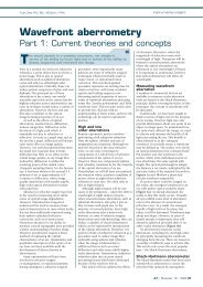
<strong>Automated</strong> <strong>refraction</strong><br />
Design and applications<br />
When the first autorefractor was developed over 30 years<br />
ago, many optometrists were concerned about the impact<br />
such devices would have on the profession. <strong>Today</strong>, those<br />
concerns are all but forgotten, with the eyecare profession<br />
positively embracing objective <strong>refraction</strong> technology.<br />
The reason for its increasing popularity is<br />
primarily that automated <strong>refraction</strong><br />
devices offer speed, reasonable accuracy<br />
and repeatability. Indeed, there are<br />
publications to support the notion that<br />
autorefractors are more accurate and<br />
repeatable than retinoscopy 1,2 . However,<br />
one should not forget that retinoscopy<br />
provides certain information not provided<br />
by conventional autorefractors. For<br />
example, it informs the practitioner about<br />
media opacities and significant ocular<br />
aberration. This article describes the<br />
technology employed by various<br />
autorefractors, and considers aspects such<br />
as direct prescribing and where these<br />
instruments are potentially inaccurate.<br />
Why the need?<br />
The need to deliver a comprehensive eye<br />
examination (in terms of detection and<br />
diagnosis of disease) means that many<br />
practitioners will benefit from additional<br />
information that provides a valuable basis<br />
upon which to conduct a subjective<br />
<strong>refraction</strong>. A comprehensive eye<br />
examination means a complete symptoms<br />
and history, ophthalmic investigation<br />
(including subjective <strong>refraction</strong>) and<br />
finally and most importantly, a discussion<br />
of the findings. All this, together with new<br />
guidelines on shared care with diabetic,<br />
glaucoma and cataract protocols, means<br />
that practitioners are faced with the<br />
challenge of completing all these tasks<br />
within a fixed time frame. An autorefractor<br />
will, therefore, increase the speed and<br />
efficiency of the <strong>refraction</strong> process.<br />
Academic studies require unbiased<br />
refractive data. The <strong>refraction</strong> produced by<br />
some autorefractors has been shown to be<br />
more repeatable than retinoscopy, and as<br />
repeatable as subjective <strong>refraction</strong> in<br />
cyclopleged subjects 2 . The use of these<br />
instruments in delivering repeatable,<br />
unbiased data is invaluable in studies<br />
investigating myopia development.<br />
Basic design<br />
Autorefractors basically comprise of an<br />
infrared source, a fixation target and a<br />
Badal optometer. An infrared light source<br />
(around 800-900nm) is used primarily<br />
because of the ocular transmission and<br />
reflectance characteristics achieved at the<br />
sclera 3 . At this wavelength, light is reflected<br />
back from the deeper layers of the eye<br />
(choroid and sclera 4 ) and this, together<br />
with the effects of longitudinal chromatic<br />
aberration, means that a systematic error<br />
of approximately -0.50DS must be added<br />
to compensate for ocular <strong>refraction</strong> with<br />
visible light.<br />
A variety of targets have been used for<br />
fixation ranging from less interesting ‘stars’<br />
to pictures with peripheral blur to further<br />
relax accommodation. All autorefractors<br />
now use the fogging technique to relax<br />
accommodation prior to objective<br />
<strong>refraction</strong>. Practitioners may recall in the<br />
past patients stating that the target is<br />
blurred prior to measurements being taken<br />
– this is the effect of the fogging lens.<br />
However, even with this fogging technique,<br />
micro fluctuations in accommodation<br />
occur up to 0.50DS 5 . Some of this effect is<br />
counteracted by averaging multiple<br />
readings – however, the error is not<br />
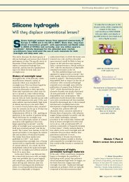
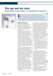
eliminated. The Shin Nippon NVISION-K<br />
5001 (Figure 1) uses an open view to<br />
allow patients an unrestricted binocular<br />
view of a distance target, e.g. a distance<br />
object.<br />
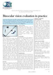
Virtually all autorefractors have a Badal<br />
optometer within the measuring head. The<br />
Badal lens system has two main<br />
advantages. Firstly, there is a linear<br />
relationship between the distance of the<br />
Badal lens to the eye and the ocular<br />
<strong>refraction</strong> within the meridian being<br />
measured. Secondly, with a Badal lens<br />
system, the magnification of the target<br />
remains constant irrespective of the<br />
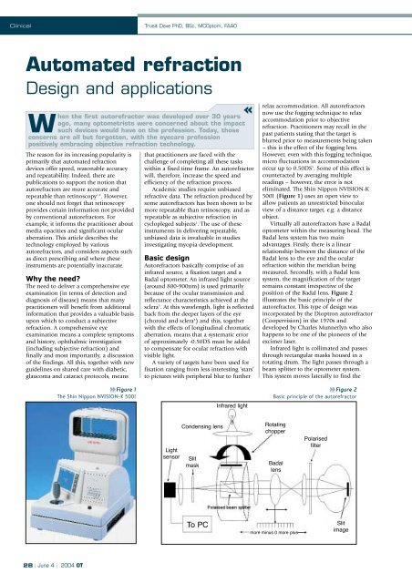
position of the Badal lens. Figure 2<br />
illustrates the basic principle of the<br />
autorefractor. This type of design was<br />
incorporated by the Dioptron autorefractor<br />
(Coopervision) in the 1970s and<br />
developed by Charles Munnerlyn who also<br />
happens to be one of the pioneers of the<br />
excimer laser.<br />
Infrared light is collimated and passes<br />
through rectangular masks housed in a<br />
rotating drum. The light passes through a<br />
beam splitter to the optometer system.<br />
This system moves laterally to find the<br />
Figure 1<br />
The Shin Nippon NVISION-K 5001<br />
Infrared light<br />
Figure 2<br />
Basic principle of the autorefractor<br />
Light<br />
sensor<br />
Condensing lens<br />
Slit<br />
mask<br />
Rotating<br />
chopper<br />
Badal<br />
lens<br />
Polarised<br />
filter<br />
To PC<br />
more minus 0 more plus<br />
Slit<br />
image<br />
28 | June 4 | 2004 OT
Clinical<br />
optimal focus of the slit on the retina.<br />
Optimal focus is achieved when a peak<br />
signal is received from the light sensor.<br />
The polarising beam splitter effectively<br />
removes reflected light from the cornea<br />
whereas the slit image on the retina passes<br />
through the polarised beam splitter. The<br />
system measures at least three meridians<br />
of the eye in order to derive the refractive<br />
power of the eye using the sine-squared<br />
function 6 .<br />
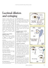
The sine-squared function of ocular<br />
astigmatism describes the variation of<br />
meridional astigmatic power. Thus, for any<br />
given prescription sph/-cylxθ, the power<br />
along any given meridian is given by the<br />
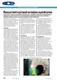
formula sph+(cyl x sine2θ). Figure 3<br />
illustrates the sine-squared function for<br />
the prescription +2.00/-5.00x90.<br />
Autorefractors only need to calculate<br />
the power at three chosen meridians in<br />
order to calculate the sphero-cylindrical<br />
prescription using the sine-squared<br />
function. Basically, the three power<br />
measurements at the three respective<br />
meridians provide three points on the<br />
sine-squared function graph. From this,<br />
the rest of the curve can be extrapolated in<br />
order to calculate the maximum and<br />
minimum power values, i.e. the principal<br />
focal planes.<br />
Three types of autorefractors<br />
Fundamentally, there are three types of<br />
autorefractors which derive objective<br />
<strong>refraction</strong> by:<br />
• Image quality analysis<br />
• Scheiner double pin-hole <strong>refraction</strong><br />
• Retinoscopy<br />
Each of these will now be discussed in<br />
more detail.<br />
Image quality analysis<br />
This method is not used very much in<br />
modern-day autorefractors. It was<br />
originally used in the Dioptron<br />
autorefractor. However, for completeness,<br />
it will be discussed here.<br />
In Figure 2, the basic design of the<br />
autorefractor is described. Here, the<br />
optimal position of the Badal optometer<br />
lens was determined by the output signal<br />
of the light sensor. The rotating drum<br />
effectively produces a light/dark<br />
alternating target. The light sensor matches<br />
the intensity profile of the incoming light<br />
from the eye, to the light intensity pattern<br />
from the rotating slit drum.<br />
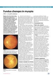
Figure 4 shows how the image analyser<br />
determines the optimal position of the<br />
Badal optometer lens. A low intensity<br />
profile tells the autorefractor that the<br />
Badal lens is not in the correct position to<br />
correct the meridional power. When the<br />
intensity profile reaches a peak, the Badal<br />
optometer reading is taken to signify the<br />
power of the meridian being measured.<br />
Once this is performed for three<br />
meridians, the sine-squared function is<br />
used to derive the sphero-cylindrical<br />
prescription.<br />
Perrigin et al 7 compared the refractive<br />
data from the Dioptron Nova with<br />
subjective <strong>refraction</strong> in a clinical setting for<br />
236 patients. Dioptron and subjective data<br />
had an agreement of ±0.50 for 74% of eyes<br />
with respect to mean spherical equivalent<br />
power. Mailer 8 compared the accuracy of<br />
the Dioptron II pre and post cycloplegia<br />
with subjective <strong>refraction</strong> in 84 patients.<br />
There was 46% agreement to ±0.25DS for<br />
spheres, 51% for ±0.25D cylinders and<br />
44% for mean spherical equivalent. After<br />
cycloplegia, there was 47%, 51% and 51%<br />
agreement respectively. Furthermore,<br />
cylinder axis agreement was 46% without,<br />
and 29% with cycloplegia for ±5 degrees<br />
axis error. The author concluded that the<br />
Dioptron provided a useful “starting<br />
point” to subjective <strong>refraction</strong> 8 . Similar<br />
conclusions have been drawn in other<br />
studies 9,10 .<br />
Signal<br />
to eye<br />
Signal<br />
to eye<br />
Signal to<br />
light sensor<br />
Signal to<br />
light sensor<br />
Sub-optimal position of Badal optometer lens<br />
Result in: low detector output<br />
Optimal position of Badal optometer lens<br />
Result in: high detector output<br />
Figure 3<br />
The sine-squared function describes the meridional power variation<br />
of sphero-cylindrical refractive error<br />
Figure 4<br />
Auto<strong>refraction</strong> using the image analysis principle<br />
Distance light<br />
source<br />
Scheiner double<br />
pin-hole<br />
CROSSED<br />
DIPLOPIA<br />
Narrow pin-hole<br />
Semi-silvered mirror<br />
Dual LEDs<br />
Condensing lens Objectives<br />
EYE<br />
NO<br />
DIPLOPIA<br />
Lateral movement of LEDs to<br />
enable correct alignment at<br />
the photodetector<br />
UNCROSSED<br />
DIPLOPIA<br />
Dual photodetector<br />
Figure 5<br />
Optical principles of the Scheiner double pin-hole<br />
Figure 6<br />
Principle of the Scheiner double pin-hole based autorefractors<br />
29 | June 4 | 2004 OT
Clinical<br />
Trusit Dave PhD, BSc, MCOptom, FAAO<br />
Study<br />
Comparison<br />
Subjects<br />
Results<br />
Conclusion<br />
Kinge et al, 1996<br />
BJO<br />
Subjective <strong>refraction</strong> vs.<br />
Nidek AR-1000 &<br />
Humphrey 500<br />
448 eyes subjective <strong>refraction</strong><br />
448 eyes Humphrey 500<br />
160 eyes Nidek AR-1000<br />
Cycloplegia<br />
Mean age 20.1 (SD 1.1)<br />
Both autorefractors over minus<br />
Humphrey 500 by R -0.23D<br />
L -0.20<br />
Nidek AR -1000 by R -0.13,<br />
L -0.11.<br />
Both p
Clinical<br />
Knife edge at<br />
focal point of O<br />
Knife edge at<br />
focal point of O<br />
Objective (O)<br />
Detector<br />
Objective (O)<br />
Detector<br />
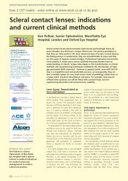
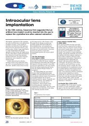
Figure 7a<br />
Knife edge test for myopic eye. The motion of the reflex across the<br />
detector provides information on the nature of the refractive error.<br />
The speed of the reflex describes the magnitude of <strong>refraction</strong><br />
Figure 7b<br />
Knife edge test for an emmetropic eye. The reflex on the detector<br />
moves over most of the surface<br />
general, two LEDs (light emitting diodes)<br />
are imaged to the pupillary plane. These<br />
effectively act as a modified Scheiner pinhole<br />
by virtue of the narrow pencils of<br />
light produced by the small aperture<br />
pinhole located at the focal point of the<br />
objective lens. A detailed analysis of<br />
Scheiner principle autorefractors can be<br />
discussed by observation of an older<br />
Scheiner autorefractor, whose optical<br />
design is available in the public domain<br />
(Figure 6) 11 .<br />
Once the LEDs are imaged in the<br />
pupillary plane, ocular <strong>refraction</strong> leads to<br />
doubling of the LEDs if refractive error is<br />
present. After <strong>refraction</strong>, the retinal image<br />
of the LEDs reflects from the retina back<br />
out of the eye. However, light emanating<br />
from the eye is again reflected by a semisilvered<br />
mirror to a dual photodetector. In<br />
order to differentiate between crossed and<br />
uncrossed doubling, the LEDs flicker<br />
alternately at a high frequency. The dual<br />
photodetector image is designed to image<br />
only one of the two LEDs in each half. As<br />
a result, crossed and uncrossed diplopia<br />
can be detected. As the LED system is<br />
moved back and forth (according to the<br />
type of diplopia), the separation of the<br />
diplopic images varies on the<br />
photodetector. When the retinal image is<br />
single, a single LED image is centred over<br />
both photodetectors. The LED position<br />
corresponds to the refractive error in that<br />
meridian. In the case of astigmatism, four<br />
LEDs are used and the power<br />
perpendicular to the meridian under test is<br />
measured.<br />
It is apparent from Figure 6 that<br />
alignment of the photodetectors is<br />
important. Basically, it is important that<br />
both the patient fixation and instrument<br />
axes are coaxial. If this condition is not<br />
met then effectively the objective<br />
<strong>refraction</strong> is conducted from an off-axis<br />
point – and this leads to error.<br />
Manufacturers have attempted to reduce<br />
these errors with auto-alignment systems.<br />
Practitioners who ‘over-ride’ this function,<br />
by continually holding down the joystick<br />
button, may effectively increase the error<br />
of measurement due to the possibility of<br />
misalignment.<br />
There have been considerable studies<br />
evaluating the accuracy of Scheiner-based<br />
autorefractors. This article reviews studies<br />
published in the last 11 years (Table 1).<br />
Retinoscopy based<br />
Some autorefractors (Welch Allen<br />
Suresight and Power Refractor II) use<br />
infra-red video<strong>refraction</strong>. A grating, or slit,<br />
is produced by a rotating drum. Similar<br />
principles to retinoscopy are used where<br />
the speed of the reflex is used as an<br />
indicator of the patient’s <strong>refraction</strong>. The<br />
optical configuration was originally<br />
described by Foucault and was used to test<br />
the surface quality of mirrors. It is now<br />
better known as the ‘knife test’ where the<br />
slit (or ‘knife’ as it was originally called)<br />
was produced using a pair of blades side<br />
by side. The basic optical construction is<br />
shown in Figures 7a and 7b.<br />
The slit is used to determine the<br />
refractive power of the eye. The speed and<br />
direction of the movement of the reflex is<br />
detected by photodetectors and computed<br />
to derive the meridional power. Figure 8<br />
shows the configuration of the detectors.<br />
The vertical slit calculates the <strong>refraction</strong> of<br />
the vertical meridian. The system detects<br />
that the vertical meridian is measured by<br />
the way each detector senses the slit as it<br />
passes over the pupil. The time difference<br />
from the slit reaching each of the<br />
detectors allows the autorefractor to detect<br />
the meridian under investigation. The<br />
oblique slit will likewise initiate a<br />
different time dependent response from<br />
the detectors, and thus derive the power<br />
within the oblique meridian.<br />
Once the optimum movement is<br />
derived corresponding to neutralisation in<br />
that meridian, the dioptric value is plotted<br />
on the sine-squared function (Figure 3) to<br />
derive the sphero-cylindrical <strong>refraction</strong>.<br />
Prescribing directly<br />
from autorefractors<br />
Although many studies have evaluated the<br />
accuracy and repeatability of<br />
autorefractors relative to subjective<br />
<strong>refraction</strong>, the ability of patients to adapt<br />
and tolerate these prescriptions has not<br />
been addressed. Clearly, there is a margin<br />
of error that patients are willing to<br />
tolerate; the question is whether this<br />
margin of error is within the variability<br />
encountered with autorefractors. Strang et<br />
al 12 conducted an interesting study to<br />
investigate patient tolerance to<br />
autorefractor prescriptions.<br />
Forty-seven subjects with a mean age<br />
36.7 (±16.7) and no ocular pathology,<br />
and not requiring bifocal or PALs, were<br />
enrolled into their study. Six<br />
autorefractors (Canon RL-10, Hoya AR-<br />
559, Humphrey AR-595, Nidek AR-800,<br />
Nikon NR-5500 and Topcon RM-A7000)<br />
were used to refract the patients in<br />
addition to carrying out subjective<br />
<strong>refraction</strong>. Spectacles were made from the<br />
prescription of one of the six<br />
autorefractors (assigned randomly) and<br />
the practitioner. Subjects wore each<br />
prescription for two weeks without a<br />
wash-out period. Both the investigators<br />
and the subjects were masked as to the<br />
prescription being worn. After each<br />
period, subjects filled out a questionnaire.<br />
Three subjects were removed due the fact<br />
that the visual acuity result from<br />
auto<strong>refraction</strong> was below 6/9.<br />
Interestingly, two of these three were from<br />
the autorefractor and one from the<br />
clinician (a latent hypermmetrope).<br />
Table 2 shows the main results from<br />
the questionnaire from Strang et al 12 .<br />
The authors’ concluded that<br />
prescribing purely from the autorefractor<br />
prescription was unfeasible in practice.<br />
Similar studies need to be conducted with<br />
modern-day autorefractors and<br />
instruments capable of automated<br />
subjective <strong>refraction</strong> such as the Topcon<br />
BV-1000 and post <strong>refraction</strong> system.<br />
Auto<strong>refraction</strong> in<br />
irregular eyes<br />
Increasing numbers of patients are having<br />
surgery to correct ocular <strong>refraction</strong>. Does<br />
automated <strong>refraction</strong> have a close<br />
correlation to subjective <strong>refraction</strong> in<br />
these cases? Corneal shape post refractive<br />
surgery is clearly modified in the majority<br />
of procedures. Furthermore, specific<br />
algorithms are used in lasers which ablate<br />
the cornea to reduce aberrations and<br />
permit increased ablation zone diameters.<br />
Most autorefractors (all Scheiner based)<br />
perform <strong>refraction</strong> through a fixed pupil<br />
diameter. Therefore, the influence of<br />
overall <strong>refraction</strong> throughout the<br />
pupillary plane will not be addressed. In<br />
eyes with a normal corneal shape, the<br />
results will not be affected but in<br />
pathological eyes such as post graft,<br />
keratoconus and post refractive surgery,<br />
the departure of corneal shape from<br />
normality may induce significant errors<br />
compared to subjective <strong>refraction</strong>. Many<br />
31 | June 4 | 2004 OT
Clinical<br />
Trusit Dave PhD, BSc, MCOptom, FAAO<br />
Question<br />
In general, have you found you<br />
spectacle lenses to be:<br />
1. Very good<br />
2. Good<br />
3. Satisfactory<br />
4. Poor<br />
Would you return to the eye clinic to<br />
complain about the spectacle lenses?<br />
1. Yes<br />
2. No<br />
Which pair did you prefer?<br />
1. Number 1<br />
2. Number 2<br />
3. Equally good<br />
4. Equally bad<br />
practitioners may have encountered this in<br />
keratoconic eyes.<br />
Siganos et al 13 compared the results of<br />
auto<strong>refraction</strong> pre and post LASIK in 73<br />
eyes. They found no significant difference<br />
in pre-LASIK <strong>refraction</strong> from auto<strong>refraction</strong><br />
and subjective <strong>refraction</strong> under cycloplegia<br />
for sphere, cylinder and axis. However,<br />
post LASIK, significant differences were<br />
found for sphere and cylinder power. They<br />
concluded that retreatments should always<br />
be based on subjective <strong>refraction</strong>. Similar<br />
results were found for PRK treated eyes by<br />
Oyo-Szerenyi et al 14 .<br />
Anomalies of the vitreous have also<br />
been implicated in producing errors in<br />
automated <strong>refraction</strong>. Wong and<br />
Sampath 15 found large errors in patient a<br />
with asteroid hyalosis.<br />
Conclusions<br />
Auto<strong>refraction</strong> is a valuable tool in<br />
determining a starting point for <strong>refraction</strong>.<br />
Modern technology has resulted in<br />
improvements in design, size, speed and<br />
accuracy. There are primarily two<br />
principles utilised in current autorefractors<br />
– the Scheiner principle and the<br />
Retinoscopic principle. Improvements in<br />
target design (auto-fogging distance targets<br />
and open view autorefractors) attempt to<br />
relax accommodation in patients. The<br />
results of auto<strong>refraction</strong> post refractive<br />
surgery, and in eyes with corneal<br />
distortion, should always be viewed with<br />
suspicion. Aberrometers may help to<br />
provide a better starting point for<br />
<strong>refraction</strong> in these instances, as the best-fit<br />
sphero-cylindrical correction to the<br />
emerging wavefront of the eye is<br />
addressed, i.e. the <strong>refraction</strong> of the entire<br />
pupillary plane will be measured.<br />
Unfortunately, the cost of these systems is<br />
significantly greater than the cost of<br />
autorefractors and is therefore not likely to<br />
replace automated <strong>refraction</strong> at the present<br />
time.<br />
Autorefractor<br />
68% reported<br />
good or very good<br />
38.3% would<br />
return<br />
Clinician<br />
85.1%<br />
reported<br />
good<br />
or very good<br />
10.6%<br />
would return<br />
Significance<br />
P=0.05, i.e. the<br />
investigator<br />
prescription<br />
performed<br />
significantly better<br />
P=0.002,<br />
i.e. a significant<br />
difference in<br />
the responses<br />
51.1% preferred the optometrist’s prescription and<br />
19.1% the autorefractor;<br />
29.8% found both equally good<br />
Table 2<br />
Main results from Strang et al 12 questionnaire<br />
About the author<br />
Dr Trusit Dave is Director of Optimed,<br />
Clinical Consultant for Topcon GB, and a<br />
partner in private practice in Coventry.<br />
References<br />
1. Safir A, Hyams L, Philpot J, Jagerman<br />
LS (1970) Studies in <strong>refraction</strong>.<br />
The precision of retinoscopy.<br />
Arch. Ophthalmol. 84: 49–61.<br />
2. Zadnik K, Mutti DO, Adams AJ (1992)<br />
The repeatability of measurements of<br />
the ocular components. Invest.<br />
Ophthalmol. Vis. Sci. 33: 2325–33.<br />
3. Geeralts WJ and Berry ? (1968) Ocular<br />
spectral characteristics as related to<br />
hazards from lasers and other light<br />
sources. Am. J. Ophthalmol. 66: 15-20.<br />
4. Charman WN (1980) Reflection of<br />
plane polarized light by the retina.<br />
Br. J. Physiol. Opt. 32: 78-93.<br />
5. Charman WN and Herron G (1988)<br />
Fluctuations in accommodation: a<br />
review. Ophthal. Physiol. Opt. 8:<br />
153-164.<br />
Slit produced<br />
by rotating drum<br />
Photodetectors<br />
Vertical meridian<br />
analysis<br />
6. Keating MP and Carroll JP (1976)<br />
Blurred imagery and the cylinder sinesquared<br />
law. Am. J. Optom. Physiol. Opt.<br />
53: 66-69.<br />
7. Perrigin DM, Grosvenor T, Reis A,<br />
Perrigin J (1984) Comparison of<br />
Dioptron Nova refractive data with<br />
conventional refractive data.<br />
Am. J. Optom. Physiol. Opt. 61 (7):<br />
479-83.<br />
8. Mailer CM (1978) Automatic<br />
<strong>refraction</strong> and the private<br />
ophthalmologist: Dioptron II<br />
compared with subjective examination.<br />
Can. J. Ophthalmol. 13 (4): 252-7.<br />
9. Polse DA and Kerr KE (1975) An<br />
automatic objective optometer.<br />
Description and clinical evaluation.<br />
Arch. Ophthalmol. 93 (3): 225-31.<br />
10. Holtmann H and Kroll P (1975)<br />
Results with automatic <strong>refraction</strong><br />
(author’s transl). Klin. Monatsbl.<br />
Augenheilkd. 166 (4): 532-6.<br />
11. Wood ICJ, Papas E, Burghardt D and<br />
Hardwick G (1984) A clinical<br />
evaluation of the Nidek autorefractor.<br />
Ophthal. Physiol. Opt. 4: 169-178.<br />
12. Strang NC, Gray LS, Winn B and Pugh<br />
JR (1998) Clinical evalutation of<br />
patient tolerances to autorefractor<br />
prescriptions. Clin. & Exp. Optom.<br />
81 (3): 112-118.<br />
13. Siganos DS, Popescu C, Bessis N and<br />
Papastergiou G (2003)<br />
Autorefractometry after laser in situ<br />
keratomileusis. J. Cat. & Refract. Surg.<br />
29 (1): 133-137.<br />
14. Oyo-Szerenyi KD, Wienecke L,<br />
Businger U and Schipper I (1997)<br />
Auto<strong>refraction</strong>/autokeratometry and<br />
subjective <strong>refraction</strong> in untreated and<br />
photorefractive keratectomy-treated<br />
eyes. Arch. Ophthalmol. 115 (2):<br />
157-164.<br />
15. Wong SC and Sampath R (2002)<br />
Erroneous automated <strong>refraction</strong> in a<br />
case of asteroid hyalosis. J. Cat. &<br />
Refract. Surg. 28 (9): 1707-1708.<br />
Figure 8<br />
The detector configuration<br />
Motion path<br />
Motion path<br />
Oblique meridian<br />
analysis<br />
32 | June 4 | 2004 OT