- Page 1 and 2: SERVICE MANUAL Published in Jul.’
- Page 3 and 4: Safety precautions This booklet pro
- Page 5 and 6: 1. Installation Precautions WARNING
- Page 7 and 8: • Do not pull on the AC power cor
- Page 9 and 10: 2DF 1-5-3 Image formation problems
- Page 11 and 12: 2DF 1-6-5 Developing section ......
- Page 13 and 14: 2DF 1-1-1 Specifications Type .....
- Page 15 and 16: 2DF 1-1-2 Parts names and their fun
- Page 17 and 18: 2DF 1-1-3 Machine cross section Lig
- Page 19 and 20: 2DF (2) Drive system 2 (paper feed
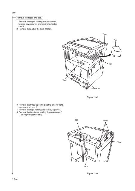
- Page 21 and 22: 2DF 1-3-1 Unpacking and installatio
- Page 23: 2DF Unpack. Figure 1-3-2 Unpacking
- Page 27 and 28: 2DF Install the toner disposal tank
- Page 29 and 30: 2DF 1-3-2 Setting initial copy mode
- Page 31 and 32: 2DF (2) Setting department manageme
- Page 33 and 34: 2DF (4) Machine default Auto drawer
- Page 35 and 36: 2DF 1-3-4 Installing the key counte
- Page 37 and 38: 2DF 1-3-5 Installing the drawer hea
- Page 39 and 40: 2DF 5. Remove the screw and then th
- Page 41 and 42: 2DF 1-3-7 Installing the large pape
- Page 43 and 44: 2DF 10. Turn the four leveling bolt
- Page 45 and 46: 2DF 1-3-8 Installing the saddle fin
- Page 47 and 48: 2DF 12. Align the rail retainer wit
- Page 49 and 50: 2DF 20. Fit the eject tray to the f
- Page 51 and 52: 2DF 9. Insert the rib of the front
- Page 53 and 54: 2DF 6. Adjust the height of the lef
- Page 55 and 56: 2DF 1-3-10 Installing the Facsimile
- Page 57 and 58: 2DF 12. Fasten the NCU unit into pl
- Page 59 and 60: 2DF This page is intentionally left
- Page 61 and 62: 2DF 24. Fasten the shield cover int
- Page 63 and 64: 2DF 30. Take the power label from t
- Page 65 and 66: 2DF 1-3-11 Installing the Printing
- Page 67 and 68: 2DF 1-3-12 Installing the Scanning
- Page 69 and 70: 2DF 9. Fasten the shield cover into
- Page 71 and 72: 2DF 6. Insert the 8-pin connector o
- Page 73 and 74: 2DF 4. Close the conveying cover an
- Page 75 and 76:
2DF 12. Remove a screw, turn the me
- Page 77 and 78:
2DF 19. Attach the copy tray. Copy
- Page 79 and 80:
2DF 6. Remove the two screws and th
- Page 81 and 82:
2DF 1-3-16 Installing the Network F
- Page 83 and 84:
2DF 8. Remove the film that fixes t
- Page 85 and 86:
2DF 17. Fasten the shield cover int
- Page 87 and 88:
2DF 23. Take the power label from t
- Page 89 and 90:
2DF (2) Maintenance mode item list
- Page 91 and 92:
2DF Section Mode setting Image proc
- Page 93 and 94:
2DF Maintenance Description item No
- Page 95 and 96:
2DF Maintenance Description item No
- Page 97 and 98:
2DF Maintenance Description item No
- Page 99 and 100:
2DF Maintenance Description item No
- Page 101 and 102:
2DF Maintenance Description item No
- Page 103 and 104:
2DF Maintenance Description item No
- Page 105 and 106:
2DF Maintenance item No. Descriptio
- Page 107 and 108:
2DF Maintenance Description item No
- Page 109 and 110:
2DF Maintenance Description item No
- Page 111 and 112:
2DF Maintenance Description item No
- Page 113 and 114:
2DF Maintenance Description item No
- Page 115 and 116:
2DF Maintenance Description item No
- Page 117 and 118:
2DF Maintenance item No. U161 U162
- Page 119 and 120:
2DF Maintenance Description item No
- Page 121 and 122:
2DF Maintenance Description item No
- Page 123 and 124:
2DF Maintenance Description item No
- Page 125 and 126:
2DF Maintenance item No. Descriptio
- Page 127 and 128:
2DF Maintenance Description item No
- Page 129 and 130:
2DF Maintenance Description item No
- Page 131 and 132:
2DF Maintenance Description item No
- Page 133 and 134:
2DF Maintenance Description item No
- Page 135 and 136:
2DF Maintenance Description item No
- Page 137 and 138:
2DF Maintenance Description item No
- Page 139 and 140:
2DF Maintenance item No. Descriptio
- Page 141 and 142:
2DF Maintenance Description item No
- Page 143 and 144:
2DF Maintenance Description item No
- Page 145 and 146:
2DF Maintenance item No. Descriptio
- Page 147 and 148:
2DF Maintenance Description item No
- Page 149 and 150:
2DF Maintenance Description item No
- Page 151 and 152:
2DF This page is intentionally left
- Page 153 and 154:
2DF Maintenance Description item No
- Page 155 and 156:
2DF Jam code Contents See pape 10 1
- Page 157 and 158:
2DF 1. Paper feed section • No pa
- Page 159 and 160:
2DF Feed switch 1 (FSW1) does not t
- Page 161 and 162:
2DF • Multiple sheets in copier v
- Page 163 and 164:
2DF 4. Eject section • Misfeed in
- Page 165 and 166:
2DF The switchback eject switch (SB
- Page 167 and 168:
2DF • An original jam in the orig
- Page 169 and 170:
2DF (3) Paper misfeeds Problem Caus
- Page 171 and 172:
2DF Problem Causes/check procedures
- Page 173 and 174:
2DF Problem Causes/check procedures
- Page 175 and 176:
2DF Problem Causes/check procedures
- Page 177 and 178:
2DF Problem Causes/check procedures
- Page 179 and 180:
2DF Problem Causes/check procedures
- Page 181 and 182:
2DF (2) Self diagnostic codes Code
- Page 183 and 184:
2DF Code Contents Causes Remarks Ch
- Page 185 and 186:
2DF Code Contents Causes Remarks Ch
- Page 187 and 188:
2DF Code Contents Causes Remarks Ch
- Page 189 and 190:
2DF Code Contents Causes Remarks Ch
- Page 191 and 192:
2DF Code Contents Causes Remarks Ch
- Page 193 and 194:
2DF Code Contents Causes Remarks Ch
- Page 195 and 196:
2DF 1-5-3 Image formation problems
- Page 197 and 198:
2DF (2) No image appears (entirely
- Page 199 and 200:
2DF (6) A black line appears longit
- Page 201 and 202:
2DF (12)The leading edge of the ima
- Page 203 and 204:
2DF (18)Image center does not align
- Page 205 and 206:
2DF Problem Causes Check procedures
- Page 207 and 208:
2DF Problem Causes Check procedures
- Page 209 and 210:
2DF Problem Causes Check procedures
- Page 211 and 212:
2DF Problem Causes Check procedures
- Page 213 and 214:
2DF Problem Causes/check procedures
- Page 215 and 216:
2DF (2) Running a maintenance item
- Page 217 and 218:
2DF • Removing the paper feed pul
- Page 219 and 220:
2DF 4. Raise the bypass separation
- Page 221 and 222:
2DF 12. Remove the stop ring of the
- Page 223 and 224:
2DF (3) Adjustment after roller and
- Page 225 and 226:
2DF (3-3) Adjusting the center line
- Page 227 and 228:
2DF (3-5) Adjusting the amount of s
- Page 229 and 230:
2DF (2) Detaching and refitting the
- Page 231 and 232:
2DF 3. Insert the two frame securin
- Page 233 and 234:
2DF (3) Detaching and refitting the
- Page 235 and 236:
2DF (4) Adjusting the skew of the l
- Page 237 and 238:
2DF • Refitting the ISU 1. Fit th
- Page 239 and 240:
2DF (7) Adjusting the longitudinal
- Page 241 and 242:
2DF (9) Adjusting magnification of
- Page 243 and 244:
2DF (11) Adjusting the scanner cent
- Page 245 and 246:
2DF 1-6-4 Drum section (1) Detachin
- Page 247 and 248:
2DF 1-6-5 Developing section (1) De
- Page 249 and 250:
2DF 1-6-7 Fixing section (1) Detach
- Page 251 and 252:
2DF (4) Detaching and refitting the
- Page 253 and 254:
2DF (6) Detaching and refitting the
- Page 255 and 256:
2DF 1-7-2 Replacing the backup ROM
- Page 257 and 258:
2DF 2-1-1 Paper feed section The pa
- Page 259 and 260:
2DF MPCB RCL CN16-B6 RSW CN10-A2 FC
- Page 261 and 262:
2DF 2-1-2 Main charging section The
- Page 263 and 264:
2DF 2-1-3 Optical section The optic
- Page 265 and 266:
(2) Image printing The image data s
- Page 267 and 268:
2DF The dimensions of the laser bea
- Page 269 and 270:
(1) Formation of magnetic brush The
- Page 271 and 272:
(3) Single component developing sys
- Page 273 and 274:
2DF 2-1-5 Transfer and separation s
- Page 275 and 276:
2DF 2-1-6 Cleaning and charge erasi
- Page 277 and 278:
2DF Fixing temperature 165°C/329°
- Page 279 and 280:
2DF Secondary paper feed end RCL EM
- Page 281 and 282:
2DF (2) Switches and sensors 20 21
- Page 283 and 284:
2DF (3) Motors 5 6 7 12,13,14 9 1 8
- Page 285 and 286:
2DF 2-3-1 Power source PCB Power so
- Page 287 and 288:
2DF Terminals (CN) Voltage Remarks
- Page 289 and 290:
The main PCB (MPCB) consists of the
- Page 291 and 292:
2DF Terminals (CN) Voltage Remarks
- Page 293 and 294:
2DF Terminals (CN) Voltage Remarks
- Page 295 and 296:
2DF Terminals (CN) Voltage Remarks
- Page 297 and 298:
2DF 2-3-3 Operation unit PCB Operat
- Page 299 and 300:
2DF K19 C1 CN3 1 B1 B3 17 C2 C3 C4
- Page 301 and 302:
2DF Terminals (CN) Voltage Remarks
- Page 303 and 304:
2DF C111 C110 C5 C118 L1 4 CN6 1 C1
- Page 305 and 306:
2DF C9 9 R39 R38 C22 Q2 L4 C21 C8 T
- Page 307 and 308:
2DF 1418 P 944 P 944 P 1418 P 1418
- Page 309 and 310:
2DF Timing chart No. 4 Copying an A
- Page 311 and 312:
2DF Timing chart No. 6 Copying an A
- Page 313 and 314:
2DF Timing chart No. 8 Duplex copyi
- Page 315 and 316:
2DF Timing chart No. 10 Continuous
- Page 317 and 318:
2DF Maintenance mode Item No. Mode
- Page 319 and 320:
2DF Adjusting order Item Image Desc
- Page 321 and 322:
2DF Periodic maintenance procedures
- Page 323 and 324:
2DF Optional devices supplied parts
- Page 325 and 326:
General wiring diagram 2DF A B C D