Download - Obd2be.com
Download - Obd2be.com
Download - Obd2be.com

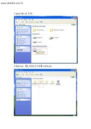
Create successful ePaper yourself
Turn your PDF publications into a flip-book with our unique Google optimized e-Paper software.
,<br />
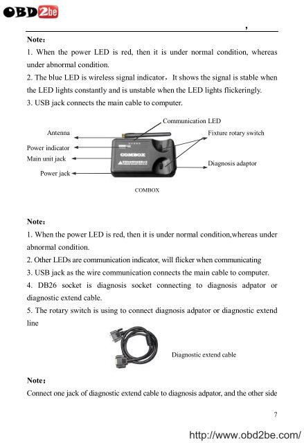
Note:<br />
1. When the power LED is red, then it is under normal condition, whereas<br />
under abnormal condition.<br />
2. The blue LED is wireless signal indicator,It shows the signal is stable when<br />
the LED lights constantly and is unstable when the LED lights flickeringly.<br />
3. USB jack connects the main cable to <strong>com</strong>puter.<br />
Antenna<br />
Power indicator<br />
Main unit jack<br />
Power jack<br />
Communication LED<br />
Fixture rotary switch<br />
Diagnosis adaptor<br />
COMBOX<br />
Note:<br />
1. When the power LED is red, then it is under normal condition,whereas under<br />
abnormal condition.<br />
2. Other LEDs are <strong>com</strong>munication indicator, will flicker when <strong>com</strong>municating<br />
3. USB jack as the wire <strong>com</strong>munication connects the main cable to <strong>com</strong>puter.<br />
4. DB26 socket is diagnosis socket connecting to diagnosis adpator or<br />
diagnostic extend cable.<br />
5. The rotary switch is using to connect diagnosis adpator or diagnostic extend<br />
line<br />
Diagnostic extend cable<br />
Note:<br />
Connect one jack of diagnostic extend cable to diagnosis adpator, and the other side<br />
http://www.obd2be.<strong>com</strong>/<br />
7