MiniMax® NT Series - Pentair
MiniMax® NT Series - Pentair
MiniMax® NT Series - Pentair

Create successful ePaper yourself
Turn your PDF publications into a flip-book with our unique Google optimized e-Paper software.
Air Requirements<br />
14<br />
INDOOR VE<strong>NT</strong>ING—General Requirements<br />
The vent pipe must be the same size or larger than specified adaptor. The MiniMax <strong>NT</strong> <strong>Series</strong> heaters are capable of a<br />
360-degree discharge rotation and operate with a positive vent static pressure and with a vent gas temperature less than 400° F.<br />
Please note the allowable vent runs for each stack pipe diameter are different and can not be exceeded. The total<br />
length of the horizontal run must not exceed the length that is listed below in the tables.<br />
Note that each 90-degree elbow reduces the maximum horizontal vent run by 8 feet and each 45-degree elbow in the vent<br />
run reduces the maximum vent run by 4 feet. See the tables below for the maximum vent lengths using a 90-degree and<br />
45-degree elbows.<br />
The MiniMax <strong>NT</strong> <strong>Series</strong> is a “Category III” Appliance and is an induced-draft pool and spa heater which uses positive<br />
pressure to push flue gases through the vent pipe to the outside. This requires a completely sealed vent system—single<br />
wall vent pipe with sealed-seams and joints. Flue gases under positive pressure may escape into the dwelling with any<br />
cracks or loose joints in the vent pipe, or improper vent installation. The vent pipe must be of a sealed-seam construction<br />
such as those listed for use with “Category III Appliances” and for operating temperatures above 350°. The use of listed<br />
thimbles, roof jacks and/or side vent terminals are required; and the proper clearances to combustible materials must be<br />
maintained in accordance with type of vent pipe employed—in the absence of a clearance recommendation by the vent<br />
pipe manufacturer, the requirements of the Uniform Mechanical Code should be met. The ventilation air requirements<br />
for the MiniMax <strong>NT</strong> <strong>Series</strong> heater can be found on page 15. It is recommended that vent runs over 18 feet be insulated<br />
to reduce condensation related problems and/or the use of a condensate trap in the vent run close to the heater may be<br />
necessary in certain installations such as cold climates. The MiniMax <strong>NT</strong> <strong>Series</strong> is suitable for through-the-wall venting,<br />
see table and dimensions below.<br />
Recommended sources for Side-wall vent hood terminals include: The Field Controls Co. (2308 Airport Road,<br />
Kingston, NC 28501, (800)742-8368) and Tjernlund Products Inc. (1601 Ninth Street, White Bear Lake, MN<br />
55110, (800) 255-4208)—consult manufacturer for model information and availability.<br />
CAUTION<br />
Do NOT combine exhaust vent pipes to a common exhaust vent in multiple unit installations. Run separate vent pipes.<br />
45 ft. Maximum Vent Run, 5 in. O.D. vent (Equiv. ft.)<br />
Additional 90° elbows<br />
after first elbow<br />
Quantity<br />
Reduced<br />
Max.<br />
Additional 45° elbows<br />
after first elbow<br />
Quantity<br />
Reduced<br />
Max.<br />
1 (2 total) 37<br />
( 2 total)<br />
41<br />
2 (3 total) 29<br />
( 3 total)<br />
37<br />
3 (4 total) 21<br />
( 4 total)<br />
33<br />
Table 7. Table 8.<br />
22 ft. Maximum Vent Run, 4 in. O.D. vent (Equiv. ft.)<br />
Additional 90° elbows<br />
after first elbow<br />
Q uantity Reduced<br />
Max.<br />
Additional 45° elbows<br />
after first elbow<br />
Quantity<br />
Reduced<br />
Max.<br />
1 (2 total) 14<br />
ft.<br />
( 2 total)<br />
18 ft.<br />
2 (3 total) — ( 3 total)<br />
14 ft.<br />
3 (4 total) — ( 4 total)<br />
—<br />
Table 9.<br />
C<br />
F<br />
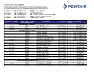
THROUGH WALL VE<strong>NT</strong> KITS FOR HEATERS<br />
Part<br />
Number<br />
Dim.<br />
A<br />
Dim.<br />
B<br />
Dim.<br />
C<br />
Dim.<br />
D<br />
Dim.<br />
E<br />
Dim. F<br />
471532<br />
4 in. Dia.<br />
6 in. Dia.<br />
8 ½ in.<br />
6 5/16 in.<br />
12<br />
5/8 in.<br />
10 5/8 in.<br />
B<br />
A<br />
E<br />
471543<br />
5 in. Dia.<br />
8 in. Dia.<br />
8 ½ in.<br />
8 in.<br />
12<br />
5/8 in.<br />
10 5/8 in.<br />
Figure 9.<br />
D<br />
P/N <strong>NT</strong>SM03 Rev. B 2-11-04