MiniMax® NT Series - Pentair
MiniMax® NT Series - Pentair
MiniMax® NT Series - Pentair

Create successful ePaper yourself
Turn your PDF publications into a flip-book with our unique Google optimized e-Paper software.
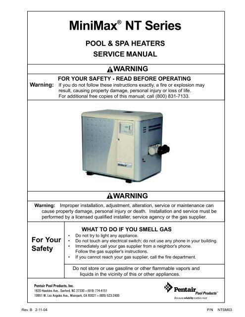
MiniMax ® <strong>NT</strong> <strong>Series</strong><br />
1 1<br />
POOL & SPA HEATERS<br />
SERVICE MANUAL<br />
Warning:<br />
WARNING<br />
FOR YOUR SAFETY - READ BEFORE OPERATING<br />
If you do not follow these instructions exactly, a fire or explosion may<br />
result, causing property damage, personal injury or loss of life.<br />
For additional free copies of this manual; call (800) 831-7133.<br />
WARNING<br />
Warning: Improper installation, adjustment, alteration, service or maintenance can<br />
cause property damage, personal injury or death. Installation and service must be<br />
performed by a licensed qualified installer, service agency or the gas supplier.<br />
For Your<br />
Safety<br />
WHAT TO DO IF YOU SMELL GAS<br />
• Do not try to light any appliance.<br />
• Do not touch any electrical switch; do not use any phone in your building.<br />
• Immediately call your gas supplier from a neighbor's phone.<br />
Follow the gas supplier's instructions.<br />
• If you cannot reach your gas supplier, call the fire department.<br />
Do not store or use gasoline or other flammable vapors and<br />
liquids in the vicinity of this or other appliances.<br />
<strong>Pentair</strong> Pool Products, Inc.<br />
1620 Hawkins Ave., Sanford, NC 27330 • (919) 774-4151<br />
10951 W. Los Angeles Ave., Moorpark, CA 93021 • (805) 523-2400<br />
Rev. B 2-11-04 P/N <strong>NT</strong>SM03
Table of Contents<br />
Introduction ............................................................................................................................. 3<br />
Important Notice .......................................................................................................................................................................... 3<br />
Code Requirements ..................................................................................................................................................................... 3<br />
Safety Rules ................................................................................................................................................................................ 4<br />
Installation Tips ........................................................................................................................ 4<br />
Dimensions ............................................................................................................................... 5<br />
Installation Outdoors/Indoors ................................................................................................. 6<br />
Installation on Floors Constructed of Combustible Materials ....................................................................................................... 6<br />
Gas Requirements ................................................................................................................... 7-8<br />
Gas Line Installations .................................................................................................................................................................. 7<br />
Sediment Traps ........................................................................................................................................................................... 7<br />
Pipe Sizing for Gas Line Installations .......................................................................................................................................... 8<br />
Residential Propane 2 Stage Regulation ..................................................................................................................................... 8<br />
Residential natural Gas 2 Stage Regulation ................................................................................................................................ 8<br />
Testing Gas Pressure .............................................................................................................. 9<br />
Gas Pressure Requirements ....................................................................................................................................................... 9<br />
Water Connections................................................................................................................... 10-11<br />
Plumbing Connections ................................................................................................................................................................. 10<br />
Manual By-Pass .......................................................................................................................................................................... 10<br />
Valves .......................................................................................................................................................................................... 11<br />
Below Pool Installation ................................................................................................................................................................ 11<br />
Pressure Switch Adjustment ........................................................................................................................................................ 11<br />
Reversing Headers ................................................................................................................... 12-13<br />
Air Requirements ..................................................................................................................... 14-17<br />
Venting — Indoor Installations ..................................................................................................................................................... 14 - 16<br />
Venting — Outdoor Installations .................................................................................................................................................. 17<br />
Electrical Wiring ....................................................................................................................... 18-21<br />
Wiring Schematic for all Dual Voltage Blowers ............................................................................................................................ 19<br />
Wiring Diagram ............................................................................................................................................................................ 20<br />
Schematic for Remote Controls (2 and 3 Wire) ........................................................................................................................... 21<br />
Basic System Operation .......................................................................................................... 22-24<br />
Heater Operation — Firing Sequence — Ignition Failure — Hard Lock Out ................................................................................ 22<br />
Starting Operation — HSI Electronic Ignition Lighting/Operation ................................................................................................. 23<br />
Chemical Balance ........................................................................................................................................................................ 24<br />
Maintenance ............................................................................................................................. 25-28<br />
Pressure Relief Valve .................................................................................................................................................................. 25<br />
Spring and Fall Operation — Winter Operation ........................................................................................................................... 25<br />
Burner Tray Removal ................................................................................................................................................................... 26<br />
Desooting .................................................................................................................................................................................... 27<br />
Reinstalling Heat Exchanger ....................................................................................................................................................... 28<br />
Troubleshooting ....................................................................................................................... 29-46<br />
Glossary .................................................................................................................................... 47<br />
MiniMax <strong>NT</strong> (Standard) Parts List & Exploded View (Dual Voltage) ........................................... 48-49<br />
MiniMax <strong>NT</strong> Low NOx Parts List & Exploded View (Dual Voltage) ............................................ 50-51<br />
Warranty Information ...............................................................................................................<br />
P/N <strong>NT</strong>SM03 Rev. B 2-11-04<br />
2<br />
Back Cover
Important Notice<br />
3<br />
MiniMax ® <strong>NT</strong> <strong>Series</strong><br />
Pool and Spa Heaters<br />
....For the installer and operator of the MiniMax <strong>NT</strong> <strong>Series</strong> pool and spa heaters. The manufacturer’s<br />
warranty may be void if, for any reason, the heater is improperly installed and/or operated. Be sure to follow<br />
the instructions set forth in this manual. If you need any more information, or if you have any questions<br />
regarding to this pool heater, please contact <strong>Pentair</strong> Pool Products, Inc. at (800) 831-7133.<br />
These heaters are designed for the heating of swimming pools and spas, and should never be<br />
employed for use as space heating boilers, general purpose water heaters, in non-stationary<br />
installations, or for the heating of salt water.<br />
CAUTION<br />
OPERATING THIS HEATER CO<strong>NT</strong>INUOUSLY AT WATER TEMPERATURE BELOW 68° F. WILL CAUSE<br />
HARMFUL CONDENSATION AND WILL DAMAGE THE HEATER AND WILL VOID THE WARRA<strong>NT</strong>Y.<br />
Do not use the heater to protect pools or spas from freezing if the final maintenance temperature desired is<br />
below 68° F. as this will cause condensation related problems.<br />
CODE REQUIREME<strong>NT</strong>S<br />
The installation must conform with local codes or, in the absence of local codes, with the National Fuel Gas<br />
Code, ANSI Z223.1/NFPA 54 and/or CSA B149.1, Natural Gas and Propane Installation Codes. If an<br />
external electrical source is utilized, the heater, when installed, must be electrically grounded and bonded in<br />
accordance with local codes or, in the absence of local codes, in the USA, with the National Electrical<br />
Code, ANSI/NFPA 7; in Canada, with Canadian Electric Code, CSA C22.1-98.<br />
Rev. B 2-11-04 P/N <strong>NT</strong>SM03
Safety Rules<br />
1. Spa or hot tub water temperatures should never exceed<br />
104° F. A temperature of 100° F. is considered safe for<br />
a healthy adult. Special caution is suggested for young<br />
children.<br />
2. Drinking of alcoholic beverages before or during spa<br />
or hot tub use can cause drowsiness which could lead<br />
to unconsciousness and subsequently result in<br />
drowning.<br />
3. Pregnant women beware! Soaking in water above 100°<br />
F. can cause fetal damage during the first three months<br />
of pregnancy (resulting in the birth of a brain-damaged<br />
or deformed child). Pregnant women should stick to<br />
the 100° F. maximum rule.<br />
4. Before entering the spa or hot tub, the user should<br />
check the water temperature with an accurate<br />
thermometer. Spa or hot tub thermostats may err in<br />
regulating water temperatures by as much as 4° F.<br />
5. Persons with a medical history of heart disease,<br />
circulatory problems, diabetes or blood pressure<br />
problems should obtain their physician's advice before<br />
using spas or hot tubs.<br />
6. Persons taking medication which induce drowsiness,<br />
such as tranquilizers, antihistamines or anticoagulants<br />
should not use spas or hot tubs.<br />
4<br />
WARNING<br />
Should overheating occur or the gas supply fail to shut off, turn off the manual gas control valve to the heater.<br />
Do not use this heater if any part has been under water. Immediately call a qualified service technician to<br />
inspect the heater and to replace any part of control system and gas control which has been under water.<br />
Installation Tips<br />
CAUTION<br />
CAUTION<br />
DO NOT INSTALL HEATER<br />
UNDER ANY ROOF<br />
OVERHANG NOT HAVING A<br />
PROPER RAIN GUTTER.<br />
DO NOT PLACE GAS<br />
SUPPLY LINE UNION<br />
COUPLING INSIDE OF<br />
HEATER JACKET.<br />
(Follow Recommendations of<br />
National Fuel Gas Code NFPA 54.)<br />
DO NOT INSTALL the heater under an overhang<br />
of less than three (3) feet from the top of the heater.<br />
The area under the overhang must be open on three<br />
sides. Overhangs must be such that flue products<br />
are not diverted into living spaces. Heaters installed<br />
under overhangs must be protected from direct roof<br />
water drainage by gutters and the like.<br />
DO NOT INSTALL the heater in locations which<br />
will permit the accumulation of leaves or other<br />
combustible material on or around the base of the<br />
heater.<br />
DO NOT RESTRICT<br />
ACCESS TO HEATER<br />
WITH PIPING.<br />
DO NOT INSTALL the heater in a location that<br />
will allow sprinklers to operate near the heater<br />
equipment since the water may cause damage to the<br />
controls and/or electronics.<br />
P/N <strong>NT</strong>SM03 Rev. B 2-11-04
Dimensions<br />
5<br />
OUTDOOR VE<strong>NT</strong>ILATION<br />
15.50<br />
7.35<br />
2 in. SOCKET<br />
24.05<br />
30.63<br />
LEG<br />
14.50<br />
MODEL<br />
200<br />
"A" DIM.<br />
21.63<br />
250 24.63<br />
300<br />
27.63<br />
LEG<br />
8.84<br />
4.88<br />
400 34.13<br />
"A" DIM.<br />
DIMENSIONS IN INCHES<br />
INDOOR VE<strong>NT</strong>ILATION<br />
15.50<br />
INDOOR VE<strong>NT</strong> ADAPTOR<br />
P/N 460506 4 in. Kit<br />
P/N 460507 5 in. Kit<br />
7.35<br />
2 in. SOCKET<br />
2.00<br />
24.05<br />
30.63<br />
LEG<br />
14.50<br />
MODEL<br />
200<br />
"A" DIM.<br />
21.63<br />
250 24.63<br />
300<br />
27.63<br />
LEG<br />
8.84<br />
4.88<br />
400 34.13<br />
"A" DIM.<br />
Rev. B 2-11-04 P/N <strong>NT</strong>SM03
6<br />
Installation - Outdoors/Indoors<br />
The heater should not be installed closer than 6 inches to any<br />
fences, walls or shrubs at any side or back, nor closer than 18<br />
inches at the plumbing side. A minimum clearance of 24 inches<br />
must be maintained at the front of the heater. The heater should<br />
be installed at least 5 feet away from the pool or spa.<br />
6"<br />
IMPORTA<strong>NT</strong>!<br />
Under certain conditions, “heavy rains or unusually high winds”,<br />
it may be necessary to install an outdoors vent. In this situation,<br />
use vent adaptor P/N 460507 and outdoor vent P/N 471357.<br />
NOTE<br />
From the point where the flue products leave the heater, that point<br />
MUST be a minimum of (4) feet below, and (4) feet horizontally from<br />
or (1) foot above any door, window or gravity inlet to a building.<br />
24"<br />
DOOR<br />
6"<br />
OUTDOOR INSTALLATION<br />
VE<strong>NT</strong>ING GUIDELINES<br />
3'<br />
4' Min. Below<br />
4' Minimum<br />
(Horizontal)<br />
Clearance<br />
18"<br />
4'<br />
Figure 1.<br />
Figure 3.<br />
INSTALLATION ON FLOORS CONSTRUCTED<br />
OF COMBUSTIBLE MATERIALS<br />
The heater may be placed on a “combustible floor”<br />
using the method listed below:<br />
a) The heater must be installed on a non-combustible floor<br />
and at least six inches from any combustible material or<br />
wall. Construct a non-combustible base from masonry<br />
blocks as illustrated in Figure 2.<br />
BASE FOR USE ON COMBUSTIBLE FLOORS<br />
INDOOR INSTALLATIONS<br />
The heater must be placed in a suitable room on a non-combustible<br />
floor or on a non-combustible base and in an area where leakage<br />
from heat exchanger or water connections will not result in<br />
damage to the area adjacent to the heater or the structure. When<br />
such locations cannot be avoided, it is recommended that a<br />
suitable drain pan with adequate drainage, be installed under the<br />
heater. The pan must not restrict air flow.<br />
Installations in basements, garages, or underground structures<br />
where flammable liquids may be stored must have the heater<br />
elevated 18 inches from the floor using a non-combustible base.<br />
The following minimum clearances from combustible materials<br />
must be provided.<br />
SHEET METAL<br />
BLOCKS<br />
Figure 2.<br />
6" Min.<br />
6" Min.<br />
HOLLOW MASONARY BLOCKS, NOT LESS THAN 4" THICK<br />
(LAID WITH ENDS UNSEALED AND JOI<strong>NT</strong>S MATCHED<br />
FOR AIR CIRCULATION). COVER BLOCKS WITH<br />
24 GA. (MIN.) GALVANIZED SHEET METAL.<br />
Side Front Back Top<br />
Water Connection 18 in. 24 in. - -<br />
Remaining 6 in. - 6 in. -<br />
Ceiling Clearance - - - 18 in.*<br />
*To ceiling or roof.<br />
CAUTION<br />
Chemicals should not be stored near the heater installation.<br />
Combustion air can be contaminated by corrosive chemical<br />
fumes which can void the warranty.<br />
P/N <strong>NT</strong>SM03 Rev. B 2-11-04
Gas Requirements<br />
7<br />
GAS LINE INSTALLATIONS<br />
Before installing the gas line, be sure to check which<br />
gas the heater has been designed to burn. This is<br />
important because different types of gas require<br />
different gas pipe sizes. The rating plate on the heater<br />
will indicate which gas the heater is designed to burn.<br />
Tables 1-5, shown on page 8, shows which size pipe<br />
is required for the distance from the gas meter to the<br />
heater. The table is for natural gas at a specific gravity<br />
of .65 and propane at a specific gravity of 1.5.<br />
When sizing gas lines, calculate three (3) additional<br />
feet of straight pipe for every elbow used.<br />
When installing the gas line, avoid getting dirt, grease<br />
or other foreign material in the pipe as this may cause<br />
damage to the gas valve, which may result in heater<br />
failure.<br />
The gas meter should be checked to make sure that it<br />
will supply enough gas to the heater and any other<br />
appliances that may be used on the same meter.<br />
The gas line from the meter will usually be of a larger<br />
size than the gas valve supplied with the heater.<br />
Therefore a reduction of the connecting gas pipe will<br />
be necessary. Make this reduction as close to the<br />
heater as possible.<br />
CAUTION<br />
The heater and any other gas appliances must be<br />
disconnected from the gas supply piping system<br />
during any pressure testing on that system, (greater<br />
than ½ PSIG).<br />
The heater and its gas connection must be leak<br />
tested before placing the heater in operation. Do not<br />
use flame to test the gas line. Use soapy water or<br />
another nonflammable method.<br />
A manual main shut-off valve must be installed<br />
externally to the heater. See Figure 4.<br />
SEDIME<strong>NT</strong> TRAPS<br />
Install a sediment in front of the gas controls.<br />
The sediment trap shall be either a tee fitting with<br />
a capped nipple in the bottom outlet which can be<br />
removed for cleaning, as illustrated below, or a<br />
other device recognized as an effective sediment<br />
trap. All gas piping should be tested after installation<br />
in accordance with local codes. See Figure 4.<br />
WARNING<br />
Do not install the gas line union inside the heater<br />
cabinet. This will void your warranty.<br />
GAS<br />
SUPPLY<br />
UNION<br />
TEE<br />
FITTING<br />
GAS<br />
VALVE<br />
MANUAL<br />
SHUT OFF<br />
VALVE<br />
NIPPLE<br />
3 INCHES<br />
MINIMUM<br />
HEATER CABINET<br />
Figure 4.<br />
CAP<br />
Rev. B 2-11-04 P/N <strong>NT</strong>SM03
Installation (Gas Line)<br />
8<br />
Pipe Sized For Length Of Run In Equivalent Feet<br />
MODEL<br />
NAT<br />
PIPE SIZING FOR GAS LINE CONNECTIONS<br />
MAXIMUM EQUIVALE<strong>NT</strong> PIPE LENGTH<br />
Natural gas at 1000 B.T.U. per Cubic Foot<br />
Propane Gas at 2500 B.T.U. per Cubic Foot<br />
Table 1.<br />
1 /2” 3 /4”<br />
1 ” 1 -1/4”<br />
1 -1/2”<br />
2 ” 2-1/2”<br />
PRO<br />
NAT<br />
PRO<br />
NAT<br />
PRO<br />
NAT<br />
PRO<br />
NAT<br />
PRO<br />
NAT<br />
PRO<br />
200<br />
- 20’<br />
30’<br />
80’<br />
125’<br />
250’<br />
450’<br />
600’<br />
- - - - - -<br />
250<br />
- 10’<br />
20’<br />
50’<br />
70’<br />
150’<br />
250’<br />
500’<br />
600’<br />
- - - - -<br />
300<br />
- - 10’<br />
30’<br />
50’<br />
100’<br />
200’<br />
350’<br />
400’<br />
600’<br />
- - - -<br />
400<br />
- - - 10’<br />
20’<br />
60’<br />
100’<br />
150’<br />
200’<br />
450’<br />
400’<br />
- - -<br />
NAT<br />
PRO<br />
“RESIDE<strong>NT</strong>IAL” PROPANE 2 STAGE REGULATION<br />
In many Propane gas line installations, the gas supplier and/or installer will utilize a two stage regulation process<br />
where by at the supply tank they will install the first stage gas regulator, which would be at a higher pressure, usually<br />
10 psi. This higher pressure allows for a much longer distance and in a much smaller pipe size. Then within a short<br />
distance of the pool heater, usually around 24 inches, they will install a second regulator, which is the second stage,<br />
and this would be set at the required inlet pressure of the heater.<br />
See “Gas Pressure Requirement Charts”<br />
Stage One "High Pressure" Gas Pipe Sizing<br />
10 PSI @ 2500 B.T.U. Per CU. FT.<br />
MAXIMUM EQUIVALE<strong>NT</strong> PIPE LENGTH<br />
M odel 0 to 50 Ft.<br />
50<br />
to 100 Ft.<br />
100 to 150 Ft.<br />
75<br />
through 400 1 /2 in.<br />
1 /2 in.<br />
1/2 in.<br />
Stage Two "Low Pressure" Gas Pipe Sizing<br />
Stage 2 set at 14 in. W.C.<br />
MAXIMUM EQUIVALE<strong>NT</strong> PIPE LENGTH<br />
M odel 0 to 10 Ft.<br />
10 to 20 Ft.<br />
75<br />
through 400 3 /4 in.<br />
3/4 in.<br />
Table 2. Table 3.<br />
“RESIDE<strong>NT</strong>IAL” NATURAL GAS 2 STAGE REGULATION<br />
In many Natural gas line installations, the gas supplier and/or installer may utilize a two stage regulation process<br />
where by at the streets main gas supply they will install the first stage gas regulator, which would be at a higher<br />
pressure. This higher pressure is usually set at 2 psi or 5 psi and can be for long distances and in a much smaller pipe<br />
size. Then within a short distance of the pool heater, generally around 24 inches, they will install a second regulator,<br />
which is the second stage. This second stage regulator would be set at the minimum operating pressure for the heater.<br />
For “Natural Gas <strong>Pentair</strong> Pool Heaters” the minimum is 7 inches W.C.<br />
See “Gas Pressure Requirement Charts”<br />
Stage One "High Pressure" Gas Pipe Sizing<br />
2 PSI @ 1000 B.T.U. Per CU. FT.<br />
MAXIMUM EQUIVALE<strong>NT</strong> PIPE LENGTH<br />
M odel 0 to 50 Ft.<br />
50<br />
to 100 Ft.<br />
100 to 150 Ft.<br />
75<br />
through 300 1 /2 in.<br />
1 /2 in.<br />
1/2 in.<br />
350<br />
& 400 3 /4 in.<br />
3 /4 in.<br />
3/4 in.<br />
5 PSI @ 1000 B.T.U. Per CU. FT.<br />
75<br />
through 400 1 /2 in.<br />
1 /2 in.<br />
1/2 in.<br />
Stage Two "Low Pressure" Gas Pipe Sizing<br />
Stage 2 set at 7 in. W.C.<br />
MAXIMUM EQUIVALE<strong>NT</strong> PIPE LENGTH<br />
M odel 0 to 10 Ft.<br />
10 to 20 Ft.<br />
75<br />
through 300 3 /4 in.<br />
3/4 in.<br />
350<br />
& 400 3 /4 in.<br />
1 in.<br />
Stage 2 set at 7 in. W.C.<br />
75<br />
through 400 3 /4 in.<br />
1 in.<br />
Table 4. Table 5.<br />
P/N <strong>NT</strong>SM03 Rev. B 2-11-04
Testing Gas Pressure<br />
9<br />
1. Push the power switch to “OFF”.<br />
2. Turn the gas valve knob to “OFF”.<br />
3. Remove 1/8 in. NPT plug on the<br />
outlet side of the valve and screw in<br />
the fitting from the Manometer kit.<br />
4. Connect the Manometer hose to the<br />
fitting.<br />
5. Turn the gas valve knob to “ON”.<br />
6. Turn on the heater and read the<br />
Manometer.<br />
7. The Manometer must read<br />
4 in. W.C. for natural gas or<br />
11 in. W.C. for propane, on<br />
manifold side of the gas valve,<br />
while operating.<br />
8. If reading is below specified; check<br />
the inlet pressure while the heater is<br />
running to make sure of proper<br />
supply before attempting adjustments.<br />
9. For adjustment, remove the Regulator<br />
Adjustment Cap and using a screwdriver<br />
turn the screw clockwise to increase -<br />
counterclockwise to decrease gas pressure.<br />
CAUTION<br />
The use of Flexible Connectors (FLEX) is NOT<br />
recommended as they cause excessive high gas<br />
pressure drops.<br />
Inlet<br />
GAS PRESSURE REQUIREME<strong>NT</strong>S*<br />
Natural Propane<br />
Maximum inlet gas pressure 10 in. WC 14 in. WC<br />
Minimum inlet gas pressure **5 in. WC 12 in. WC<br />
Normal manifold pressure 4 in. WC 11 in. WC<br />
*All Readings are taken with the heater fired. Any adjustments<br />
or readings made with heater off will give incorrect readings.<br />
** 6 in. WC for 400 model<br />
REGULATOR<br />
Manifold<br />
PRESS<br />
TAP<br />
ON<br />
OFF<br />
Figure 5.<br />
GAS VALVE<br />
Rev. B 2-11-04 P/N <strong>NT</strong>SM03
Water Connections<br />
10<br />
PLUMBING CONNECTIONS<br />
The MiniMax <strong>NT</strong> <strong>Series</strong> heater has the<br />
unique capability of direct schedule 40<br />
PVC plumbing connections. A set of<br />
bulkhead fittings is included with the<br />
MiniMax <strong>NT</strong> <strong>Series</strong> to insure<br />
conformity with <strong>Pentair</strong>’s<br />
recommended PVC plumbing<br />
procedure.<br />
CAUTION<br />
Before operating the heater on a new<br />
installation, turn on the circulation<br />
pump and bleed all the air from the<br />
filter using the air relief valve on top<br />
of the filter. If a Manual By-Pass is<br />
installed; temporarily close it to insure<br />
that all air is purged from the heater.<br />
Water should flow freely through the<br />
heater.<br />
POOL<br />
HEATER<br />
TO<br />
POOL<br />
MANUAL<br />
BY-PASS<br />
GATE<br />
CHECK VALVE<br />
VALVE<br />
Figure 6.<br />
FILTER<br />
FROM<br />
POOL<br />
CHECK<br />
VALVE<br />
PUMP<br />
Do not operate the heater unless water in the pool/spa is at the proper level.<br />
MANUAL BY-PASS<br />
Where the flow rate exceeds the maximum 120 GPM,<br />
a manual bypass should be installed and adjusted.<br />
After adjustments are made, the valve handle should<br />
be removed to avoid tampering.<br />
Adjust By-Pass until a Delta T of 28° - 32° F. is<br />
reached.<br />
Heater<br />
M odel M in. (GPM)<br />
Max. (GPM) *<br />
200<br />
20<br />
120<br />
250<br />
30<br />
120<br />
300<br />
30<br />
120<br />
In<br />
Valve<br />
Out<br />
400<br />
40<br />
120<br />
* Do not exceed the maximum recommended<br />
flow rate for the connecting piping.<br />
From<br />
Pump<br />
To<br />
Pool<br />
Table 6.<br />
Figure 7.<br />
P/N <strong>NT</strong>SM03 Rev. B 2-11-04
11<br />
Water Connections, cont’d.<br />
VALVES<br />
When any equipment is located below the surface of<br />
the pool or spa, valves should be placed in the<br />
circulation piping system to isolate the equipment<br />
from the pool or spa. Check valves are recommended<br />
to prevent back siphon.<br />
Periodically check the operation of the valve to<br />
insure proper operation.<br />
CAUTION<br />
Exercise care when installing chemical feeders so<br />
as to not allow back siphoning of chemicals into the<br />
heater, filters or pump. When chemical feeders are<br />
installed in the circulation of the piping system, make<br />
sure the feeder outlet line is down stream of the<br />
heater, and is equipped with a positive seal<br />
noncorrosive “Check Valve”, (P/N R172288), between<br />
the feeder and heater.<br />
PRESSURE SWITCH ADJUSTME<strong>NT</strong><br />
BELOW POOL INSTALLATION<br />
If the heater is below water level, the pressure<br />
switch must be adjusted. This adjustment must be<br />
done by a qualified service technician.<br />
See following CAUTION before installation.<br />
CAUTION<br />
BELOW OR ABOVE POOL INSTALLATION<br />
The water pressure switch is set in the factory at<br />
1½ PSI. This setting is for a heater installed at pool<br />
level or within 3’ above or 3’ below. If the heater is to<br />
be installed more that 3’ above or 3’ below, the water<br />
pressure switch must be adjusted by a qualified<br />
service technician.<br />
1. Backwash filter and clean the pump hair and<br />
lint basket before making any adjustment to the<br />
pressure switch.<br />
2. Switch the circulation pump on and make sure<br />
it is primed.<br />
3. Push the heater power switch on and set the<br />
thermostats to their highest temperature<br />
settings.<br />
4. Turn the adjustment knob clockwise or away<br />
from the micro-switch, until the heater shuts<br />
down.<br />
MICRO<br />
SWITCH<br />
Figure 8.<br />
FLOW SWITCH<br />
If the heater is installed more the 10’ above the pool<br />
or more than 10’ below the pool level, you will be<br />
beyond the limits of the pressure switch and a flow<br />
switch must be installed. Locate and install the flow<br />
switch externally on the outlet piping from the heater,<br />
as close as possible to the heater. Connect the flow<br />
switch wires in place of the water pressure switch wires.<br />
Clockwise<br />
Counter-Clockwise<br />
5. Turn the adjustment knob counter-clockwise<br />
1/2 turn and the heater should refire.<br />
6. Turn the pump off and the heater should shut<br />
down. If heater does not shut down, repeat<br />
procedure.<br />
7. Switch pump off and on several times to assure<br />
proper adjustment.<br />
Rev. B 2-11-04 P/N <strong>NT</strong>SM03
Reversing Headers<br />
12<br />
Reversible Inlet/Outlet Connection<br />
The MiniMax <strong>NT</strong> <strong>Series</strong> heater is factory assembled<br />
with right side inlet/outlet water connections. The<br />
inlet/outlet header can be reversed for left side water<br />
connections without removing the heat exchanger.<br />
Reversing Water Connections<br />
Tools required:<br />
Phillips Screw Driver<br />
9/16 in. Socket and Wrench<br />
1/2 in. & 9/16 in. Open Wrench<br />
NOTE<br />
Do NOT remove the high-limit and pressure<br />
switches or the thermistor from the front header<br />
during the reversing procedure, as they will be in<br />
the proper location when installed on the left side.<br />
3. Disconnect the pressure switch wiring.<br />
4. Disconnect the temperature sensor wires from<br />
the circuit board and feed them back to the<br />
header.<br />
1. Remove the right and left large inspection plates.<br />
It is not necessary to remove the top of the<br />
heater to gain access to the headers.<br />
2. Disconnect all wires from the high-limit<br />
switches except the short jumper wire.<br />
5. Remove the 8 bolts holding the main inlet/outlet<br />
head.<br />
P/N <strong>NT</strong>SM03 Rev. B 2-11-04
Reversing Headers (Return Head)<br />
13<br />
Reversible Inlet/Outlet Connection,<br />
On the MiniMax <strong>NT</strong> <strong>Series</strong> heater there is insulation<br />
installed by the factory on the return head side of the<br />
heaters. This insulation is there so that if the heads<br />
are reversed in the field, during initial installation of<br />
the heater, the high limits will be insulated from the<br />
heat radiating from the flue collector.<br />
6. Return head in position before removal. This view<br />
shows the insulation installed by the factory.<br />
Remove the 8 bolts holding the return head in place.<br />
cont’d.<br />
9. Install the temperature sensing probe by passing<br />
the wires through the hole provided on the left<br />
side of the brace panel. Route wires through the<br />
support bracket.<br />
7. When heads are removed, replace the heat<br />
exchanger tube seal gaskets.<br />
10. Reconnect all the high limit wires and the<br />
pressure switch wiring, routing the wires<br />
through the same hole as the thermostat sensor<br />
wires.<br />
8. Exchange the inlet/outlet header with the return<br />
header. Lift the insulation to allow the main head<br />
to be installed. Align header with the heat<br />
exchanger. When head is placed into position,<br />
release the insulation; it will now shield the high<br />
limits from the heat produced by the flue collector.<br />
Install header bolts, and tighten snugly by hand.<br />
(This will help avoid cross threading.) When<br />
tightening, use a cross pattern starting from the<br />
center of the header. DO NOT over tighten.<br />
11. Pump and bleed system to check the head for<br />
leaks.<br />
12. Reinstall the two large inspection plates on the<br />
appropriate side.<br />
Remember: The inlet and outlet markings<br />
on the header are still correct.<br />
Do not plumb the heater backwards.<br />
Rev. B 2-11-04 P/N <strong>NT</strong>SM03
Air Requirements<br />
14<br />
INDOOR VE<strong>NT</strong>ING—General Requirements<br />
The vent pipe must be the same size or larger than specified adaptor. The MiniMax <strong>NT</strong> <strong>Series</strong> heaters are capable of a<br />
360-degree discharge rotation and operate with a positive vent static pressure and with a vent gas temperature less than 400° F.<br />
Please note the allowable vent runs for each stack pipe diameter are different and can not be exceeded. The total<br />
length of the horizontal run must not exceed the length that is listed below in the tables.<br />
Note that each 90-degree elbow reduces the maximum horizontal vent run by 8 feet and each 45-degree elbow in the vent<br />
run reduces the maximum vent run by 4 feet. See the tables below for the maximum vent lengths using a 90-degree and<br />
45-degree elbows.<br />
The MiniMax <strong>NT</strong> <strong>Series</strong> is a “Category III” Appliance and is an induced-draft pool and spa heater which uses positive<br />
pressure to push flue gases through the vent pipe to the outside. This requires a completely sealed vent system—single<br />
wall vent pipe with sealed-seams and joints. Flue gases under positive pressure may escape into the dwelling with any<br />
cracks or loose joints in the vent pipe, or improper vent installation. The vent pipe must be of a sealed-seam construction<br />
such as those listed for use with “Category III Appliances” and for operating temperatures above 350°. The use of listed<br />
thimbles, roof jacks and/or side vent terminals are required; and the proper clearances to combustible materials must be<br />
maintained in accordance with type of vent pipe employed—in the absence of a clearance recommendation by the vent<br />
pipe manufacturer, the requirements of the Uniform Mechanical Code should be met. The ventilation air requirements<br />
for the MiniMax <strong>NT</strong> <strong>Series</strong> heater can be found on page 15. It is recommended that vent runs over 18 feet be insulated<br />
to reduce condensation related problems and/or the use of a condensate trap in the vent run close to the heater may be<br />
necessary in certain installations such as cold climates. The MiniMax <strong>NT</strong> <strong>Series</strong> is suitable for through-the-wall venting,<br />
see table and dimensions below.<br />
Recommended sources for Side-wall vent hood terminals include: The Field Controls Co. (2308 Airport Road,<br />
Kingston, NC 28501, (800)742-8368) and Tjernlund Products Inc. (1601 Ninth Street, White Bear Lake, MN<br />
55110, (800) 255-4208)—consult manufacturer for model information and availability.<br />
CAUTION<br />
Do NOT combine exhaust vent pipes to a common exhaust vent in multiple unit installations. Run separate vent pipes.<br />
45 ft. Maximum Vent Run, 5 in. O.D. vent (Equiv. ft.)<br />
Additional 90° elbows<br />
after first elbow<br />
Quantity<br />
Reduced<br />
Max.<br />
Additional 45° elbows<br />
after first elbow<br />
Quantity<br />
Reduced<br />
Max.<br />
1 (2 total) 37<br />
( 2 total)<br />
41<br />
2 (3 total) 29<br />
( 3 total)<br />
37<br />
3 (4 total) 21<br />
( 4 total)<br />
33<br />
Table 7. Table 8.<br />
22 ft. Maximum Vent Run, 4 in. O.D. vent (Equiv. ft.)<br />
Additional 90° elbows<br />
after first elbow<br />
Q uantity Reduced<br />
Max.<br />
Additional 45° elbows<br />
after first elbow<br />
Quantity<br />
Reduced<br />
Max.<br />
1 (2 total) 14<br />
ft.<br />
( 2 total)<br />
18 ft.<br />
2 (3 total) — ( 3 total)<br />
14 ft.<br />
3 (4 total) — ( 4 total)<br />
—<br />
Table 9.<br />
C<br />
F<br />
THROUGH WALL VE<strong>NT</strong> KITS FOR HEATERS<br />
Part<br />
Number<br />
Dim.<br />
A<br />
Dim.<br />
B<br />
Dim.<br />
C<br />
Dim.<br />
D<br />
Dim.<br />
E<br />
Dim. F<br />
471532<br />
4 in. Dia.<br />
6 in. Dia.<br />
8 ½ in.<br />
6 5/16 in.<br />
12<br />
5/8 in.<br />
10 5/8 in.<br />
B<br />
A<br />
E<br />
471543<br />
5 in. Dia.<br />
8 in. Dia.<br />
8 ½ in.<br />
8 in.<br />
12<br />
5/8 in.<br />
10 5/8 in.<br />
Figure 9.<br />
D<br />
P/N <strong>NT</strong>SM03 Rev. B 2-11-04
Air Requirements (Indoor)<br />
INDOOR INSTALLATION (USA ONLY)<br />
OUTDOOR SHELTER INSTALLATION (CANADA)<br />
The heater must be located as close as practical to a chimney or<br />
gas vent.<br />
vent terminated at least 24"<br />
above any object within 10 ft.<br />
See below for Vent Adaptors<br />
All products of combustion and vent gases must be completely<br />
More Than10 ft.<br />
removed to the outside atmosphere through a vent pipe which is<br />
Ridge<br />
Cap<br />
connected to the stack adaptor. A vent pipe extension of the same<br />
2 ft. min.<br />
size must be connected to the vent adaptor and extended at ;;;Vent<br />
least<br />
3 ft. min.<br />
2 feet higher than highest point of the roof within a 10 foot<br />
horizontal radius, and at least 3 feet higher than the point at which<br />
;;;<br />
it passes through the roof, or as permitted by local code; see<br />
Roof<br />
Jack<br />
Figures 10, 11 and Detail “H” of Figure 13. The vent should<br />
terminate with an approved vent cap (weather cap) for protection<br />
Chimney<br />
against rain or blockage by snow.<br />
Figure 10.<br />
15<br />
Vent Cap and<br />
Riser Furnished<br />
by Installer<br />
Chimney or Gas Vent<br />
Vent Cap and<br />
Riser Furnished<br />
by Installer<br />
Chimney or Gas Vent<br />
Outlet Air<br />
Opening<br />
Outlet Air Opening<br />
Optional<br />
Side<br />
Wall Vant<br />
Optional<br />
Side<br />
Wall Vant<br />
Heater<br />
Inlet Air<br />
Opening<br />
Heater<br />
Inlet Air Opening<br />
Figure 11.<br />
NOTE<br />
• The heater requires two uninterrupted air<br />
supply openings; one for ventilation and one to<br />
supply air for proper gas combustion. The air<br />
supply openings should be sized according to<br />
Table 10.<br />
• The openings listed in Table 10. are free open vent<br />
area—if the vents incorporate restrictive louvers, the<br />
vent openings must be increased to compensate<br />
for the area blocked by the louvers (or grills).<br />
Air supply requirements below apply to all<br />
MiniMax <strong>NT</strong> <strong>Series</strong> heaters<br />
VE<strong>NT</strong> ADAPTORS (ALL MODELS)<br />
The proper draft hood and adapter must be installed on<br />
the heater as shown below and on page 14:<br />
P art No. Vent Dia.<br />
460506<br />
4 in.<br />
460507<br />
5 in.<br />
Vent<br />
Adaptor<br />
Table 10.<br />
REQUIRED AIR SUPPLY<br />
Model<br />
Air for Combustion Air Ventilation<br />
Sq. In.<br />
Sq. In.<br />
200<br />
200<br />
200<br />
250<br />
250<br />
250<br />
300<br />
300<br />
300<br />
400<br />
400<br />
400<br />
Figure 12.<br />
Rev. B 2-11-04 P/N <strong>NT</strong>SM03
Air Requirements (Indoor)<br />
16<br />
vent terminated at least 24"<br />
above any object within 10 ft.<br />
More Than10 ft.<br />
Ridge<br />
Cap<br />
2 ft. min.<br />
;;Vent<br />
3 ft. min.<br />
J<br />
Detail H<br />
;;<br />
K<br />
Roof<br />
L Jack<br />
Chimney<br />
Vent for roof penetration installations:<br />
J<br />
must extend at least 3 ft. higher than the<br />
point at which it passes through the roof,<br />
or as permitted by local code.<br />
K<br />
must use a double-wall vent pipe through<br />
the roof penetration.<br />
L<br />
must terminate with an approved (listed)<br />
roof jack, storm collar, and vent/weather cap.<br />
Vent pipe extension:<br />
must be the same diameter as the<br />
vent connector.<br />
A<br />
B<br />
C<br />
must be suitable for use with category III<br />
appliances which have flue gas temperatures<br />
of less than 400 deg. F.<br />
may use a single wall vent pipe with<br />
permanently sealed seams and joints.<br />
G<br />
INDOOR INSTALLATIONS<br />
MINIMAX <strong>NT</strong> VE<strong>NT</strong>ING GUIDELINES<br />
H<br />
E<br />
Air Supply<br />
Ventilation<br />
F<br />
1' min.<br />
F<br />
1' min.<br />
Vent Hood<br />
Vent Hood<br />
A<br />
4'<br />
7'<br />
Air Supply<br />
Combustion<br />
G<br />
4'<br />
D<br />
Vent Hood<br />
3'<br />
B C<br />
1' min.<br />
above grade<br />
G<br />
Walkway<br />
Vent termination for side wall installations:<br />
must be not less than 7 ft. above public walkways.<br />
must be at least 3 ft. above any outside air intake located within a 10 ft. radius.<br />
must NOT be within 3 ft. of an inside corner of the structure.<br />
must be at least 1 ft. above grade.<br />
Recommended sources for<br />
side wall Vent Hood; see page 17,<br />
Section Venting.<br />
must be located the following distances away from any door, window, or gravity air inlet:<br />
D 4 ft. below<br />
E 4 ft. horizontally<br />
F 1 ft. above<br />
Air Supply<br />
See Air Supply Requirements Table.<br />
Figure 13.<br />
(Table 10. on page 15.)<br />
P/N <strong>NT</strong>SM03 Rev. B 2-11-04
Air Requirements (Outdoor)<br />
17<br />
OUTDOOR INSTALLATION ONLY (Outdoor Shelter Installation in Canada, see page 15)<br />
For outdoor installation with an exhaust grill, the heater must be placed in a suitable area on a level, noncombustible<br />
surface. Do not install the heater under an overhang with clearances less than 3 feet from the top of the heater. The<br />
area under an overhang must be open on three sides.<br />
IMPORTA<strong>NT</strong>!<br />
• For an outdoor installation it is important to ensure water is diverted from overhanging eves<br />
with a proper gutter/drainage system. The heater must be set on a level foundation for proper<br />
drainage.<br />
• Under certain conditions, “heavy rains or unusually high winds”, it may be necessary to install<br />
an outdoors vent. In this situation, use vent adaptor P/N 460507 and outdoor vent P/N 471357.<br />
Maintain minimum clearances as indicated below. Install a minimum of 4 feet below, and 4 feet horizontally from<br />
any opening to a building, see Figure 14.<br />
OUTDOOR INSTALLATION<br />
MINIMAX <strong>NT</strong> VE<strong>NT</strong>ING GUIDELINES<br />
D<br />
1'<br />
A<br />
3'<br />
4'<br />
B<br />
4'<br />
4'<br />
C<br />
E<br />
Property Line<br />
Walkway<br />
E<br />
Check local building codes<br />
for setback requirements.<br />
Figure 14.<br />
Vent Termination:<br />
Must be not less than 7 ft. above public walkways.<br />
A Must be at least 3 ft. above any forced<br />
air inlet located within a 10 ft. radius.<br />
Must be located the following distances away<br />
from any door, window, or gravity air inlet:<br />
B 4 ft. below, or<br />
C 4 ft. horizontally, or<br />
D 1 ft. above<br />
Rev. B 2-11-04 P/N <strong>NT</strong>SM03
N<br />
Electrical Wiring<br />
18<br />
Electrical Rating<br />
60 Hz 120 / 240 Volts AC, single phase<br />
NOTE<br />
• The MiniMax <strong>NT</strong> <strong>Series</strong> heater is prewired for 240 volt AC connection using the “RED/BROWN” female connector and the<br />
“WHITE” common male connector; see below, Figure 15. If you require the heater to be connected to 120 volts AC,<br />
remove the “RED/BROWN” female connector from the “WHITE” common connector; now locate the “BLUE” female<br />
connector and plug it into the “WHITE” common connector. When connecting the home wiring to the “Line Terminal<br />
Block” inside the junction box, follow the polarity as shown below. Connecting to 120 VAC, make sure that you connect<br />
the positive wire to the positive terminal (L), the neutral wire is connected to the neutral terminal (N) and the ground is<br />
connected to the ground terminal (GND); see below, Figure 16.<br />
• If any of the original wiring supplied with this heater must be replaced, installer must supply (No. 18 AWG, 600V, 105° C.<br />
U.L. approved AWM low energy stranded) copper wire or it’s equivalent. Thermal fuse wiring must be replaced with<br />
18 AWG, 600V, 150° C temperature rating. Interconnecting wiring to appliance must conform to the National Electrical<br />
Code or supercede local (wiring) codes.<br />
WARNING<br />
The installation must conform with local codes or, in the absence of local codes, with the National Fuel<br />
Gas Code, ANSI Z223.1/NFPA 54 and/or CSA B149.1, Natural Gas and Propane Installation Codes. If an<br />
external electrical source is utilized, the heater, when installed, must be electrically grounded and<br />
bonded in accordance with local codes or, in the absence of local codes, in the USA, with the National<br />
Electrical Code, ANSI/NFPA 7; in Canada, with Canadian Electric Code, CSA C22.1-98.<br />
• Always use crimp type connectors when connecting two wires.<br />
WHITE<br />
COMMON MALE<br />
CONNECTOR<br />
RED/BROWN<br />
FM CONNECTOR<br />
FOR USE WITH<br />
240 VOLT AC<br />
BLUE<br />
FM CONNECTOR<br />
FOR USE WITH<br />
120 VOLT AC<br />
TERMINAL BLOCK<br />
FOR AC INPUT<br />
120 / 240 VOLT SINGLE<br />
PHASE "See Figure Below"<br />
GREEN WIRE<br />
LINE TERMINAL BLOCK<br />
GROUND<br />
CONNECTION<br />
Figure 15.<br />
You might need<br />
to open the jacket<br />
(upper panel)<br />
for servicing the<br />
Line Terminal<br />
Block as shown in<br />
Figures 15 & 16.<br />
I<strong>NT</strong>ERNAL<br />
FACTORY WIRES<br />
WHITE WIRE<br />
NEUTRAL / WHITE 120 VAC<br />
LINE #1 FOR 240 VOLT AC<br />
BLACK WIRE<br />
L<br />
POSITIVE LINE FOR 120 VOLTS AC<br />
LINE #2 FOR 240 VOLT AC<br />
Figure 16.<br />
P/N <strong>NT</strong>SM03 Rev. B 2-11-04
Electrical Installation (Dual Voltage Blowers)<br />
19<br />
WIRING SCHEMATIC FOR ALL DUAL VOLTAGE BLOWERS<br />
120 VOLTS AC 240 VOLTS AC<br />
WHITE LINE # 1 WHITE LINE # 1<br />
YELLOW YELLOW CAP OFF<br />
JOINED<br />
ORANGE<br />
ORANGE<br />
JOINED<br />
BLACK<br />
BLACK<br />
LINE # 2<br />
PURPLE PURPLE LINE # 2<br />
BROWN<br />
BROWN<br />
BROWN<br />
= CAPACITOR CAPACITOR<br />
BROWN<br />
=<br />
NOTE FOR TEST OF THE BLOWER:<br />
1. In reference to the above terms, "CAP OFF" means to no connection.<br />
2. The term "JOINED" means the two wires are connected together and<br />
no external connection.<br />
Rev. B 2-11-04 P/N <strong>NT</strong>SM03
Electrical Installation (Dual Voltage Wiring)<br />
20<br />
MiniMax <strong>NT</strong> <strong>Series</strong> HSI Electronic Ignition Wiring Diagram<br />
(DUAL VOLTAGE w/6800 Control Board)<br />
MiniMax <strong>NT</strong> Dual Voltage W/6800 Control Board Wiring Diagram<br />
HIGH LIMIT<br />
115˚F<br />
R<br />
THERMAL FUSE<br />
W W<br />
R<br />
WATER PRESSURE<br />
SWITCH<br />
BL<br />
W<br />
R<br />
O<br />
W<br />
G<br />
R<br />
SPST EXTERNAL SWITCH<br />
W<br />
BL<br />
O<br />
P4 P7 P10 P11<br />
W<br />
O<br />
COM NO<br />
J2 J3<br />
J4 J7<br />
J10 J11<br />
JUMPER REQUIRED<br />
24V SW/HL/TFUSE VLV IGN MODULE<br />
IF NO REMOTE SWITCH<br />
AIR PRESS. SW.<br />
GAS VALVE<br />
G<br />
HOT SURFACE<br />
IGNITOR<br />
BURNER<br />
BL<br />
W<br />
IGN/120<br />
IGN/240<br />
L1<br />
L2<br />
IGN<br />
FS<br />
TH<br />
VAL<br />
GND<br />
IGN MODULE<br />
TERM<br />
BLOCK<br />
1<br />
2<br />
3<br />
4<br />
5<br />
W<br />
BK<br />
BK<br />
W<br />
BK<br />
TERM<br />
BLOCK<br />
1<br />
2<br />
3<br />
G<br />
W<br />
W<br />
O<br />
O<br />
R<br />
BK<br />
R/W<br />
BK/W<br />
BK<br />
BK/W<br />
O<br />
HIGH LIMIT<br />
150˚F<br />
W<br />
W<br />
R/W<br />
R<br />
O<br />
W<br />
SPA COM<br />
J6 J8<br />
POOL<br />
J5<br />
TPROBE<br />
J9<br />
THERMOSTAT<br />
CIRCUIT BOARD<br />
(6800)<br />
TEMP.<br />
PROBE<br />
POOL<br />
R<br />
CON-MAL(W)<br />
BK<br />
CON-FEM(BL)<br />
FOR 120 VAC<br />
W<br />
W<br />
W<br />
BK<br />
W<br />
BK<br />
120 VAC<br />
OR<br />
240 VAC<br />
Y<br />
BK<br />
O<br />
PR<br />
BLOWER<br />
F1<br />
F2<br />
24 VAC<br />
IND<br />
IF ORIGINAL FACTORY WIRING MUST BE REPLACED,<br />
INSTALLER MUST SUPPLY UL/CSA APPROVED WIRE<br />
WITH 18 AWG, 600V, 105˚ C TEMP. RATING.<br />
O<br />
W<br />
W<br />
W<br />
W<br />
W<br />
OFF SPA<br />
PR<br />
O<br />
BK<br />
Y<br />
W<br />
W<br />
W<br />
BL<br />
Y<br />
BK<br />
W<br />
W<br />
W<br />
W<br />
W<br />
BK<br />
CON-FEM(BR)<br />
FROM<br />
TRANSFORMER<br />
BOND LOG<br />
(ON THE SIDE JACKET)<br />
W<br />
BK<br />
W<br />
FOR 240 VAC ATTACH<br />
GROUND<br />
WIRE HERE<br />
W<br />
BL<br />
G<br />
Y<br />
P9<br />
MV<br />
MV<br />
W<br />
FLAME<br />
SENSOR<br />
WIRE COLOR CODE<br />
BK : BLACK<br />
BL : BLUE<br />
BR : BROWN<br />
R : RED<br />
O : ORANGE<br />
Y : YELLOW<br />
P1<br />
P2<br />
G : GREEN<br />
GY : GRAY<br />
PR : PURPLE<br />
W : WHITE<br />
R/W : RED W/WHITE TRACE<br />
BK/W : BLACK W/WHITE TRACE<br />
THERMAL FUSE WIRING MUST BE REPLACED WITH<br />
18 AWG, 600V, 150˚ C TEMP. RATING.<br />
472085C<br />
Figure 17.<br />
P/N <strong>NT</strong>SM03 Rev. B 2-11-04
Electrical Installation (Remotes)<br />
21<br />
SCHEMATIC FOR REMOTE CO<strong>NT</strong>ROL<br />
3 Wire Remote<br />
JUMPER REQUIRED IF NO 2 WIRE REMOTE SWITCH<br />
OUT<br />
EXT SWITCH<br />
RETURN<br />
24 VAC PRESS HILMT TFUSE VALVE IGNITION MOD<br />
THERMOSTAT CIRCUIT BOARD<br />
SPA COM POOL TPROBE<br />
REMOTE POOL/OFF/SPA<br />
THERMOSTAT SELECT SWITCH<br />
FRO<strong>NT</strong> PANEL<br />
POOL/<br />
OFF/SPA<br />
THERMOSTAT SELECT SWITCH<br />
Figure 18.<br />
2 Wire Remote<br />
JUMPER REQUIRED IF NO 2 WIRE REMOTE SWITCH<br />
OUT<br />
EXT SWITCH<br />
RETURN<br />
24 VAC PRESS HILMT TFUSE VALVE IGNITION MOD<br />
THERMOSTAT CIRCUIT BOARD<br />
SPA COM POOL TPROBE<br />
FRO<strong>NT</strong> PANEL<br />
POOL/OFF/SPA<br />
THERMOSTAT SELECT SWITCH<br />
Figure 19.<br />
NOTE: When connecting a remote control to the MiniMax <strong>NT</strong> <strong>Series</strong> Heater, you must install the low<br />
voltage thermostat wires in separate conduit from ANY line voltage wires. Failure to follow these<br />
instructions will cause the thermostat relay to react erratically..<br />
Rev. B 2-11-04 P/N <strong>NT</strong>SM03
Basic System Operation<br />
22<br />
TO OPERATE HEATER<br />
1. Start pump, make sure the pump is running and is primed, to close water pressure switch and<br />
supply power to heater. Be sure the pool and/or spa is properly filled with water.<br />
2. Follow the Lighting/Operating instructions on the following page.<br />
FIRING SEQUENCE<br />
1. Pump on.<br />
2. Heater on.<br />
3. T-stats call for heat.<br />
4. Pre-purge for 15 seconds (clears combustion chamber of combustible gas).<br />
5. Hot surface igniter heat up time of 40 seconds.<br />
6. Main valve opens for 7 seconds for flame rectification.<br />
7. Heater runs until desired temperature is reached.<br />
8. Gas valve closes and fan runs for 45 seconds to cool combustion chamber.<br />
IGNITION FAILURE<br />
1. If flame is not rectified in 7 seconds or less the heater goes into pre-purge for 15 seconds, then starts<br />
the ignition sequence again.<br />
2. After 3 attempts, the heater goes into hard lock<br />
out for 1 hour and tries over again.<br />
(Note: The fan will stay running during lockout.)<br />
3. To get out of the 1 hour lock out you must<br />
de-energize the heater by cutting power either<br />
with the pool / spa rocker switch or internal<br />
rocker switch.<br />
HARD LOCK OUT<br />
❖ Lock out can occur under the following condition:<br />
I<strong>NT</strong>ERNAL ROCKER SWITCH<br />
1. Heater has failed to fire on three attempts.<br />
(Under J-Box)<br />
❖ When a lock out occurs the heater shows a<br />
service light, no heat light, and the exhaust fan stays running until the one hour time out has expired.<br />
At that point the heater will attempt to fire three more times. It is important to discover why the lock<br />
out has occurred before you attempt to reset the control board.<br />
P/N <strong>NT</strong>SM03 Rev. B 2-11-04
Starting Operation (HSI)<br />
HSI ELECTRONIC IGNITION<br />
LIGHTING/OPERATION<br />
23<br />
FOR YOUR SAFETY: READ BEFORE LIGHTING<br />
WARNING<br />
If you do not follow these instructions exactly, a fire or explosion may result causing property damage, personal<br />
injury or loss of life.<br />
Do not attempt to light the heater if you suspect a natural gas leak. Lighting the heater can result in a fire or<br />
explosion which can cause personal injury, death, and property damage.<br />
A. This appliance does not have a pilot. It is<br />
equipped with an ignition device which<br />
automatically lights the burners. Do not try to<br />
light the burners by hand.<br />
B. BEFORE OPERATING, smell all around<br />
the appliance area for gas. Be sure to smell<br />
next to the floor because some gas is heavier<br />
than air and will settle on the floor.<br />
WHAT TO DO IF YOU SMELL GAS<br />
- Do not try to light any appliance.<br />
- Do not touch any electrical switch; do not use<br />
any phone in your building.<br />
- Immediately call your gas supplier from a<br />
neighbor's phone. Follow the gas supplier's<br />
instructions.<br />
- If you cannot reach your gas supplier, call the<br />
Fire Department.<br />
C. Use only your hand to push in or turn the gas<br />
control knob. Never use tools. If the knob will<br />
not push in or turn by hand, don't try to repair it,<br />
call a qualified service technician. Forced or<br />
attempted repair may result in a fire or explosion.<br />
D. Do not use this appliance if any part has been<br />
under water. Immediately call a qualified service<br />
technician to inspect the appliance and to<br />
replace any part of the control system and any<br />
gas control which has been under water.<br />
OPERATING INSTRUCTIONS<br />
1. STOP! Read the safety information above.<br />
2. Turn off electric power to the heater.<br />
3. Set the thermostat to the lowest setting.<br />
4. This appliance is equipped with an ignition<br />
device which automatically lights the burners.<br />
Do not try to light the burners by hand.<br />
5. Remove the control access door.<br />
6. Push in gas control knob slightly and turn<br />
clockwise to “OFF”.<br />
NOTE: Knob cannot be turned to “OFF” unless<br />
knob is pushed in slightly. Do not force.<br />
7. Wait five (5) minutes to clear out any gas. If you<br />
then smell gas, STOP! Follow "B" in the safety<br />
information above. If you don't smell gas, go to<br />
the next step.<br />
8. Turn gas control knob counterclockwise<br />
to “ON”. See Figure 20.<br />
9. Replace the control access door.<br />
10. Set the thermostat to the desired setting.<br />
11. Turn on the electrical power to the appliance.<br />
12. If the appliance will not operate, follow the<br />
instructions "To Turn Off Gas To Appliance"<br />
and call your service technician or gas supplier.<br />
Gas<br />
Inlet<br />
Figure 20.<br />
OFF<br />
Gas control knob shown in “ON” position.<br />
ON<br />
TO TURN OFF GAS TO APPLIANCE<br />
1. Turn off all electric power to the appliance if 4. Push in gas control knob slightly and turn<br />
service is to be performed.<br />
clockwise to "OFF". Do not force.<br />
2. Set the thermostat to lowest setting.<br />
5. Replace control access door.<br />
3. Remove control access door.<br />
Rev. B 2-11-04 P/N <strong>NT</strong>SM03
Chemical Balance<br />
POOL AND SPA WATER<br />
Your <strong>Pentair</strong> Pool Products pool heater was designed<br />
specifically for your spa or pool and will give you many<br />
years of trouble-free service, provided you keep your<br />
water chemistry in proper condition.<br />
Three major items that can cause problems with your<br />
pool heater are: improper pH, disinfectant residual, and<br />
total alkalinity. These items, if not kept properly<br />
balanced, can shorten the life of the heater and cause<br />
permanent damage.<br />
CAUTION<br />
Heat exchanger damage resulting from chemical<br />
imbalance is not covered by the warranty.<br />
WHAT A DISINFECTA<strong>NT</strong> DOES<br />
Two pool guests you do not want are algae and bacteria.<br />
To get rid of them and make pool water sanitary for<br />
swimming - as well as to improve the water's taste, odor<br />
and clarity - some sort of disinfectant must be used.<br />
Chlorine and bromine are universally approved by health<br />
authorities and are accepted disinfecting agents for<br />
bacteria control.<br />
WHAT IS A DISINFECTA<strong>NT</strong><br />
RESIDUAL?<br />
When you add chlorine or bromine to the pool water, a<br />
portion of the disinfectant will be consumed in the<br />
process of destroying bacteria, algae and other oxidizable<br />
materials. The disinfectant remaining is called chlorine<br />
residual or bromine residual. You can determine the<br />
disinfectant residual of your pool water with a reliable test<br />
kit, available from your local pool supply store.<br />
You must maintain a disinfectant residual level adequate<br />
enough to assure a continuous kill of bacteria or virus<br />
introduced into pool water by swimmers, through the air,<br />
from dust, rain or other sources.<br />
It is wise to test pool water regularly. Never allow<br />
chlorine residual to drop below 0.6 ppm (parts per<br />
million). The minimum level for effective chlorine or<br />
bromine residual is 1.4 ppm.<br />
pH - The term pH refers to the acid/alkaline balance of<br />
water expressed on a numerical scale from 0 to 14. A test<br />
kit for measuring pH balance of your pool water is<br />
available from your local pool supply store; see Table 11.<br />
pH Chart<br />
Table 11.<br />
Strongly Acid Neutral Strongly Alkaline<br />
0 1 2 3 4 5 6 7 8 9 10 11 12 13 14<br />
Muriatic Acid has a pH of about 0. Pure water is 7<br />
(neutral). Weak Lye solution have a pH of 13-14.<br />
RULE: 7.4 to 7.6 is a desirable pH range. It is essential<br />
to maintain correct pH, see Table 12.<br />
If pH becomes too high (over alkaline), it<br />
has these effects:<br />
1. Greatly lowers the ability of chlorine to destroy<br />
bacteria and algae.<br />
2. Water becomes cloudy.<br />
3. There is more danger of scale formation on the<br />
plaster or in the heat exchanger.<br />
4. Filter elements may become blocked.<br />
If pH is too low (over acid) the following<br />
conditions may occur:<br />
1. Excessive eye burn or skin irritation.<br />
2. Etching of the plaster.<br />
3. Corrosion of metal fixtures in the filtration and<br />
recirculation system, which may create brown, blue,<br />
green, or sometimes almost black stains on the<br />
plaster.<br />
4. Corrosion of copper in the heater, which may cause<br />
leaks.<br />
5. If you have a sand and gravel filter, the alum used as<br />
a filter aid may dissolve and pass through the filter.<br />
CAUTION: Do not test for pH when the chlorine<br />
residual is 3.0 ppm or higher, or bromine residual<br />
is 6.0 ppm or higher. See your local pool supply<br />
store for help in properly balancing your water<br />
chemistry.<br />
RULE: Chemicals that are acid lower pH. Chemicals<br />
that are alkaline raise pH.<br />
Table 12.<br />
6.8 7.0 7.2 7.4 7.6 7.8 8.0 8.2 8.4<br />
Add Soda, Ash or<br />
Sodium Bicarbonate<br />
pH Control Chart<br />
Marginal<br />
Ideal<br />
Marginal<br />
ALKALINITY High - Low:<br />
"Total alkalinity" is a measurement of the total amount<br />
of alkaline chemicals in the water, and control pH to a<br />
great degree. (It is not the same as pH which refers<br />
merely to the relative alkalinity/acidity balance.) Your<br />
pool water's total alkalinity should be 100 - 140 ppm to<br />
permit easier pH control.<br />
A total alkalinity test is simple to perform with a reliable<br />
test kit. You will need to test about once a week and<br />
make proper adjustments until alkalinity is in the proper<br />
range. Then, test only once every month or so to be sure<br />
it is being maintained. See your local pool dealer for<br />
help in properly balancing the water chemistry.<br />
24<br />
Add Acid<br />
P/N <strong>NT</strong>SM03 Rev. B 2-11-04
Maintenance<br />
It is recommended that you check the following items at least<br />
every six months and at the beginning of every swimming<br />
season.<br />
1. Examine the venting system. Make sure there are no<br />
obstructions in the flow of combustion and ventilation air.<br />
2. Visually inspect the main burner and the hot surface<br />
ignitor. The normal color of the flame is blue. When flame<br />
appears yellow, burners should be inspected and cleaned.<br />
Check ignitor for damage.<br />
3. Inspect the heat exchanger for soot. Clean as necessary.<br />
4. Remove burner tray and clean burners and main burner<br />
orifices.<br />
5. Keep the heater area clean and free from combustibles<br />
and flammable liquids.<br />
6. Check wire ends and wire connections. They should be<br />
clean and tight.<br />
7. Check the gas pressure as described in this manual.<br />
PRESSURE RELIEF VALVE<br />
In some installations, a pressure relief valve (PRV) is required<br />
on the MiniMax <strong>NT</strong> <strong>Series</strong>.<br />
To install a PRV, carefully<br />
drill a 3/8 in. hole in center<br />
of 3/4 in. NPT port (on<br />
main header) being careful<br />
to drill only through wall at<br />
bottom of 3/4 in. NPT port<br />
and no deeper—now thread<br />
in the 3/4 NPT PRV.<br />
NOTE: (A.S.M.E. version<br />
varies slightly. It is of<br />
bronze construction, and is<br />
supplied with the A.S.M.E.<br />
Section IV, pressure relief<br />
valve pre-installed at factory.)<br />
Test the relief valve at least<br />
once a year by lifting up<br />
lever.<br />
CAUTION<br />
REMOVE THE FLOW VALVE ASSEMBLY WHEN<br />
DRILLING THE HOLE TO INSTALL A PRV, OTHERWISE,<br />
YOU WILL DRILL I<strong>NT</strong>O THE VALVE ASSEMBLY.<br />
REMOVE FLOW VALVE<br />
BEFORE DRILLING<br />
THE NPT PORT<br />
25<br />
RELIEF<br />
VALVE<br />
FOR PRV<br />
INSTALLATION<br />
DRILL THRU<br />
THE NPT PORT<br />
Figure 22.<br />
RELIEF VALVE<br />
TO WI<strong>NT</strong>ERIZE,<br />
OPEN DRAIN VALVE<br />
STANDARD<br />
LOW-NOx<br />
Figure 21.<br />
SPRING AND FALL OPERATION<br />
A.S.M.E. VERSION<br />
If the pool is being used occasionally, do not turn the heater completely off. Set the thermostat down to 68° F. This will keep the pool<br />
and the surrounding ground warm enough to bring the pool up to a comfortable swimming temperature in a shorter period of time.<br />
WI<strong>NT</strong>ER OPERATION<br />
CAUTION<br />
OPERATING THIS HEATER CO<strong>NT</strong>INUOUSLY AT WATER TEMPERATURE BELOW 68° F. WILL CAUSE HARMFUL<br />
CONDENSATION AND WILL DAMAGE THE HEATER AND WILL VOID THE WARRA<strong>NT</strong>Y.<br />
If the pool won't be used for a month or more, turn the heater off at the main gas valve. For areas where there is no danger of water<br />
freezing, water should circulate through the heater all year long, even though you are not heating your swimming pool. The MiniMax <strong>NT</strong><br />
<strong>Series</strong> should not be operated outdoors at temperatures below 0° F. for propane and -20° F. for natural gas. Where freezing is<br />
possible, it is necessary to drain the water from the heater. This may be done by opening the drain valve, located at the inlet/outlet<br />
header, (see Figure 22.), allowing all water to drain out of the heater. It would be a good practice to use compressed air to blow the<br />
water out of the heat exchanger.<br />
CAUTION<br />
• If the heater has been drained for freezing condition, do NOT turn "ON" until the system is circulating water.<br />
• Water trapped in the heat exchanger can result in freeze damage to the exchanger or headers. Freeze damage is<br />
specifically not covered by the warranty.<br />
Rev. B 2-11-04 P/N <strong>NT</strong>SM03
26<br />
Maintenance - Burner Tray Removal<br />
At some time during the life of a heater, you may<br />
need to inspect and repair the parts of the heater that<br />
allows the gas to flow from the gas supply line into<br />
the burners. If the heater won’t fire and you wish to<br />
check these gas controls:<br />
1. Turn off the gas supply.<br />
8. You can remove the gas valve if you need to<br />
check the inlet and outlet screens. (You will<br />
have to remove the pilot tubing.)<br />
9. Remove the bracket that holds the burners in<br />
place.<br />
2. Disconnect the gas union at the heater.<br />
3. Remove the gas pipe installed into the gas<br />
valve.<br />
4. Remove the gas valve holding bracket.<br />
5. Remove the gas valve wires.<br />
6. Disconnect the ignition wire.<br />
7. Slide the burner tray out.<br />
10. Remove each burner and check for any<br />
blockages.<br />
MINIMAX <strong>NT</strong> (LOW NOx) VERSION<br />
MINIMAX <strong>NT</strong> (STANDARD) VERSION<br />
MINIMAX <strong>NT</strong> (STANDARD) VERSION<br />
11. Remove the main burner orifices and check for<br />
blockage.<br />
NOTE<br />
If the heater has been off for the winter or has been<br />
installed, but not fired for an extended period of<br />
time, insects will crawl into these orifices and the<br />
pilot orifice and prevent the heater from firing.<br />
MINIMAX <strong>NT</strong> (LOW NOx) VERSION<br />
NOTE<br />
You can use this procedure if you have to change<br />
fuel-type—natural to propane or vice versa. The<br />
parts needed to convert the MiniMax <strong>NT</strong> <strong>Series</strong><br />
are: Gas valve, main burner orifices, pilot<br />
orifice and module.<br />
P/N <strong>NT</strong>SM03 Rev. B 2-11-04
27<br />
Maintenance - Desooting<br />
COMMON CAUSES OF SOOTING<br />
1. Low gas pressure.<br />
2. Inadequate air supply or inadequate venting.<br />
3. Foreign material in burners and orifices; dirt, spider<br />
webs, etc.<br />
4. Excessive water flow can cause condensation which will<br />
contribute to sooting.<br />
To remove a light soot formation without<br />
removing the heater exchanger:<br />
1. Remove burner tray.<br />
For heavy soot accumulation which cannot<br />
be successfully removed by merely<br />
brushing, the heat exchanger must be<br />
removed from the heater.<br />
1. Disconnect the plumbing at the unions. Remove the<br />
thermistor, hi-limit wires from the inlet outlet heater.<br />
2. Remove top, inner lid, flue collector and baffles.<br />
CAUTION<br />
When lifting the heat exchanger out of the fire box,<br />
use caution so as not to damage the fire wall.<br />
WARNING<br />
Soot is combustible — DO NOT USE WIRE BRUSH!<br />
3. Using a brush with plastic or wood bristles, brush the<br />
bottom of the tubes and then the top of the tubes.<br />
4. Spray off residue with water. (Repeat steps 3-4 as needed).<br />
5. Brush off burners.<br />
6. Replace burner tray and baffles, then test fire.<br />
7. If flames burn clean, replace baffles, flue collector, and top.<br />
2. Remove the heat exchanger.<br />
3. Place exchanger in an area that won’t be affected by<br />
chemicals or strong detergents.<br />
4. After spraying the exchanger with water, use a mixture<br />
of detergent and water. Pour, spray or brush on.<br />
5. Rinse the solution off of the tubes and inspect them,<br />
repeat if necessary.<br />
Rev. B 2-11-04 P/N <strong>NT</strong>SM03
28<br />
Maintenance - Reinstalling Heat Exchanger<br />
1. Inspect fire box for damage or cracks that would allow<br />
heat to leak out into the outer cabinet and controls.<br />
5. Reconnect the inlet and outlet flange to the headers (use<br />
new flange gaskets), be careful not to move the heat<br />
exchanger and break the seal.<br />
2. Remove any old sealant from fire box.<br />
3. Apply new sealant to the fire box using a quality<br />
industrial grade R.T.V. or equivalent. The sealant must<br />
completely seal the space between the heat exchanger<br />
and fire box, so that when the heater is firing, heat does<br />
not escape to the outer cabinet.<br />
6. Reinstall baffles, flue collector, inner lid and top.<br />
CAUTION<br />
Do not store combustible material, gasoline and<br />
other flammable vapor and liquids in the vicinity<br />
of this or any other appliance.<br />
4. Place heat exchanger into the box and push down firmly,<br />
until the heat exchanger sets solidly on the fire box.<br />
P/N <strong>NT</strong>SM03 Rev. B 2-11-04
29<br />
Troubleshooting<br />
DIAGNOSTIC LIGHT OPERATION<br />
The circuit board in the MiniMax <strong>NT</strong> <strong>Series</strong> heater uses lights that are wired in sequence with the<br />
controls. The MiniMax <strong>NT</strong> <strong>Series</strong> heater still uses the same controls as the original MiniMax but this<br />
method of wiring is more helpful while troubleshooting.<br />
Sequence wiring means that each control is wired separately from the other controls and they are<br />
independently attached to the circuit board. This is how the wiring method works to help diagnose a<br />
problem.<br />
Power is connected to the board directly from the Transformer. So, if the Transformer is wired<br />
correctly and is being supplied with voltage, the Power light will be “ON”. This is not an indication that<br />
proper voltage is being supplied by the Transformer.<br />
When you push the “POOL/SPA” switch to either position and turn the thermostat knobs to “HOT”,<br />
the voltage is transferred into the circuit board, through the Thermistor, Potentiometer and down to the<br />
Remote Control terminals. If the Thermistor and Potentiometer are working the “TSTAT” light will<br />
come “ON”.<br />
If there is a Remote Control connected to these terminals, the voltage travels to the remote switch and<br />
back to the circuit board and the “AUX” light comes “ON”. If there is no Remote, there will be a jumper<br />
wire across the Remote terminals causing the “AUX” light to come “ON”.<br />
If the voltage comes across the Remote Control terminals, it will go back into the circuit board and go<br />
to the Pressure switch. If the Pump is “ON” and primed and there is enough water flow, the Pressure<br />
switch will close and the “PRESS” light will come “ON”.<br />
On the back of the circuit board, there are (3) more lights. “HIGH LIMIT”, “THERMAL CUT OFF”<br />
and “PILOT VALVE”. Voltage must travel to and through the High Limits, Thermal Cut Off and finally<br />
to the orange Pilot Valve wire before the Module will start to spark. And each time the voltage goes<br />
through a control, indicating that the control is working, the voltage must go back to the circuit board,<br />
where it lights the control indicator light.<br />
With this method of wiring we can easily see which control is not working by looking at the FIRST<br />
LIGHT that is NOT LIT because we know that voltage has to pass through the control and back to the<br />
board in order for the light to come “ON”. If the light is NOT “ON”, look at that control first.<br />
JUMPER REQUIRED IF NO REMOTE SWITCH<br />
25D K .032 D.C TAB<br />
24V<br />
J4<br />
PRESS<br />
HLMT<br />
TFUSE<br />
J7<br />
VLV<br />
JI0<br />
IGN MODULE<br />
J11<br />
J2<br />
J3<br />
1 1<br />
1<br />
1<br />
AUX.<br />
CO<strong>NT</strong>ACTS<br />
CO<strong>NT</strong>ROL RELAY<br />
CLOSE ON CALL<br />
FOR HEAT<br />
J6<br />
SPA<br />
P6<br />
J8<br />
COM<br />
P8<br />
J5<br />
POOL<br />
P5<br />
TPROBE<br />
J9<br />
P9<br />
THERMOSTAT<br />
CIRCUIT BOARD<br />
BLK<br />
BLK<br />
TEMPERATURE<br />
PROBE<br />
Figure 23.<br />
POOL OFF SPA<br />
THERMOSTAT SELECT SWITCH<br />
Rev. B 2-11-04 P/N <strong>NT</strong>SM03
30<br />
Troubleshooting<br />
DIAGNOSTIC LIGHTS<br />
1. The POWER Light indicates voltage to the<br />
Control Board from the Transformer. The<br />
POWER light will be ON without pushing the<br />
Pool/Spa switch as long as there is power being<br />
supplied to the transformer.<br />
2. The TSTAT Light or Thermostat Light will<br />
come ON if there is voltage to the<br />
Potentiometers and they are turned to the Hot<br />
Position and the water temperature is below<br />
the hot set point.<br />
3. The AUX Light or Remote Switch Light will<br />
come ON if the Remote control is operating<br />
properly and/or is attached to the back of the<br />
Control Board correctly. If the heater is not<br />
connected to a remote switch, there will be a<br />
small jumper wire attached to the Control<br />
Board to make the light come on.<br />
4. The PRESS Light is attached to the Pressure<br />
Switch and will come ON if the Pump is ON<br />
and is pumping enough water to create<br />
adequate water pressure to close the contacts<br />
on the Pressure Switch.<br />
5. The HEAT Light is attached to the MV<br />
(Main Valve) terminal on the Control Board.<br />
This terminal does not receive voltage until<br />
the Hot Surface Igniter (HSI) has been ON for<br />
40 seconds. Once voltage is sent to the Gas<br />
Valve, it should open to allow gas flow to the<br />
burners that will be ignited by the HSI.<br />
6. The SERVICE Light is a dual-purpose light.<br />
When there is a call for heat the Service Light<br />
will be ON during the 15-second pre-purge and<br />
the 40 second Hot Surface Igniter (HSI)<br />
heat-up period. The Service Light will be OFF<br />
during the 7 second trial for Ignition when the<br />
HEAT Light comes ON. If the burners fire<br />
and the Flame Sensor sends a signal to the<br />
Ignition Module that there is a successful<br />
ignition, the Service Light will stay OFF and<br />
the Heat light will stay ON. The Service light<br />
will also be ON if there is a problem with one<br />
or both of the High Limit Switches, the<br />
Thermal Fuse or the Valve (VAL) output on<br />
the Ignition Module.<br />
Figure 24.<br />
P/N <strong>NT</strong>SM03 Rev. B 2-11-04
WHT<br />
F1<br />
F2<br />
WHITE<br />
WHITE<br />
31<br />
Troubleshooting<br />
MiniMax <strong>NT</strong> <strong>Series</strong> Heater Troubleshooting/Check List<br />
1. Look at the lights, which ones are on? Review Diagnostic Lights section on previous page.<br />
2. Check for correct voltage on Secondary side of Transformer. Should be greater than 24 VAC<br />
at Orange Wire at 24 V position on Control Board.<br />
3. Check all wire connections on Module, Control Board, HSI, Flame Sensor and Gas Valve.<br />
4. Check position of HSI and Flame Sensor to Burners.<br />
5. Check for true ground and good ground connections.<br />
6. Push the Pool/Spa switch ON to the opposite side and then the thermostat from cold to hot.<br />
7. Make sure that the pump is running with a full prime and that the filter pressure is not too<br />
high or low.<br />
8. Remove any Remote Control wires from the heater Control Board and replace with the jumper<br />
wire while testing.<br />
MiniMax <strong>NT</strong> (Standard) Wire Connection<br />
ORANGE<br />
ORANGE<br />
WHITE<br />
24VAC<br />
IND<br />
TO<br />
FEMALE<br />
CONNECTOR<br />
BLACK<br />
BLACK/WHITE<br />
RED/WHITE<br />
RED<br />
TRANSFORMER<br />
ORANGE<br />
GREEN<br />
WHITE<br />
ORANGE<br />
WHITE<br />
IGNITOR<br />
FLAME SENSOR<br />
WHITE<br />
IGN/120<br />
IGNITION MODULE<br />
IGN/240<br />
L1<br />
L2<br />
IGN<br />
FS<br />
YELLOW<br />
BLUE<br />
240 OR 120VAC<br />
WHITE<br />
ORANGE<br />
WHITE<br />
TH<br />
VAL<br />
GND<br />
ORANGE<br />
120VAC<br />
WHITE<br />
WHITE<br />
AIR PRESSURE SWITCH<br />
BLUE<br />
BLACK<br />
WHITE MALE<br />
CONNECTOR<br />
YELLOW<br />
BLACK<br />
ORANGE<br />
PURPLE<br />
WHITE<br />
ORANGE<br />
JUMPER<br />
(WHT)<br />
WHITE<br />
RED<br />
BLUE<br />
WHITE<br />
RED<br />
GREEN<br />
GAS VALVE<br />
HILIMITS<br />
RED<br />
240VAC<br />
BLUE FEMALE<br />
CONNECTOR<br />
WHITE<br />
BLACK<br />
GREEN<br />
GROUND<br />
WHITE<br />
BLACK<br />
FIELD<br />
SUPPLIED<br />
120 VAC<br />
OR<br />
240 VAC<br />
60 Hz<br />
BLOWER<br />
WHITE<br />
RED/BROWN FEMALE<br />
CONNECTOR<br />
POWER TERMINAL<br />
BLOCK<br />
PE<strong>NT</strong>AIR 6800<br />
DUAL<br />
ELECTRONIC<br />
THERMOSTAT<br />
POOL (WHT)<br />
(WHT)<br />
COMMON<br />
(WHT)<br />
SPA<br />
WHITE<br />
WHITE<br />
WHITE<br />
THERMAL FUSE<br />
RED<br />
RED<br />
BLACK<br />
WHITE<br />
WHITE<br />
BLACK<br />
WHITE<br />
BLACK<br />
WHITE<br />
POWER SWITCH<br />
BLACK<br />
WHITE<br />
BLK<br />
WHITE<br />
WHITE<br />
TERMINAL BLOCK<br />
WHITE<br />
BLACK<br />
BOND LUG<br />
(ON THE SIDE OF JACKET)<br />
THERMOSTAT SWITCH<br />
POOL/OFF/SPA<br />
THERMISTOR PROBE<br />
WATER<br />
PRESSURE<br />
SWITCH<br />
Figure 25.<br />
Rev. B 2-11-04 P/N <strong>NT</strong>SM03
32<br />
Troubleshooting<br />
DIAGNOSTIC LIGHTS SHOW<br />
“POWER” ONLY!<br />
1. Check water temperature, if water has reached the desired temperature, the thermostat will cut<br />
off power to the module and the heater will stop firing. In this case the POWER Light would<br />
remain ON.<br />
2. Check the voltage on the Secondary side of the Transformer. It should be greater than 24 VAC.<br />
If the voltage is less than required, the incoming voltage may be too low for the heater to operate<br />
properly, there could be a wiring short or the wrong voltage connector may be connected to the<br />
White Male Connector. Because the Power light is not a specific 24 VAC light, it will illuminate<br />
with less than 24 VAC, so even if the Power Light is ON, the voltage may not be correct.<br />
3. The Pool/Spa switch may have inadvertently been switched Off. Even though the Pool/Spa<br />
switch does not have to be ON for the POWER Light to be ON, it does have to be pushed to<br />
either the Pool or Spa position in order to transfer voltage to the rest of the controls.<br />
4. Make sure that the Thermostat Knobs have been turned to Hot because the voltage must pass<br />
through the thermostat (potentiometer) first before going to any other control. If the<br />
potentiometer or thermistor is not working or is disconnected from the Control Board, only the<br />
POWER Light will be ON. If you suspect that this may be the problem, first check the<br />
thermistor connections on the back of the Control Board. If this does not light the T-STAT Light,<br />
connect a known functional thermistor to the Control Board. If the light still does not come on,<br />
the Control Board is bad.<br />
Figure 26.<br />
P/N <strong>NT</strong>SM03 Rev. B 2-11-04
33<br />
Troubleshooting<br />
POWER / T-STAT ONLY!<br />
1. Check that jumper has not come off of EXT SWITCH terminals.<br />
2. Remove Wires to External Switch or Remote Control System and replace with jumper.<br />
If AUX Light comes ON, the problem is in External Switch or Remote Control System.<br />
3. Check for 24 VAC at the OUT terminal of the EXT SWITCH connection.<br />
If no voltage, Control Board is bad.<br />
Figure 27.<br />
2 Wire Remote<br />
OUT<br />
EXT SWITCH<br />
RETURN<br />
POOL<br />
POTE<strong>NT</strong>IOMETER<br />
24 VAC PRESS HILMT TFUSE VALVE IGNITION MOD<br />
MODEL 6800<br />
ELECTRONIC THERMOSTAT<br />
SPA COM POOL<br />
TPROBE<br />
SPA<br />
POTE<strong>NT</strong>IOMETER<br />
PVALV LED<br />
TFUSE LED<br />
HITEMP LED<br />
Figure 28.<br />
FRO<strong>NT</strong> PANEL<br />
POOL / OFF/SPA<br />
THERMOSTAT SELECT SWITCH<br />
Rev. B 2-11-04 P/N <strong>NT</strong>SM03
WHT<br />
F1<br />
F2<br />
WHITE<br />
WHITE<br />
34<br />
Troubleshooting<br />
POWER / T-STAT / AUX ONLY!<br />
1. Be sure that Pump is ON and running with a full prime.<br />
2. Is Pump Impeller clogged.*<br />
3. Is Filter Dirty.*<br />
4. Is Pump too small or worn out.*<br />
*30 GPM is required to close the Pressure Switch. Some 2 Speed pumps will not<br />
produce 30 GPM on Low Speed.<br />
5. Check for 24 VAC at outside White Wire on PRESS connector. If no voltage, Control Board is bad.<br />
6. Check for 24 VAC at second White Wire on PRESS connector. If have voltage, Control Board is bad.<br />
7. Check that wires are attached to Pressure Switch and check for 24 VAC at both terminals. If no<br />
voltage at either terminal, wire is bad. If voltage at one terminal only, Pressure Switch is<br />
clogged, out of adjustment or bad.<br />
Figure 29.<br />
MiniMax <strong>NT</strong> (Standard) Wire Connection<br />
ORANGE<br />
ORANGE<br />
WHITE<br />
24VAC<br />
IND<br />
TO<br />
FEMALE<br />
CONNECTOR<br />
BLACK<br />
BLACK/WHITE<br />
RED/WHITE<br />
RED<br />
TRANSFORMER<br />
ORANGE<br />
GREEN<br />
WHITE<br />
ORANGE<br />
WHITE<br />
IGNITOR<br />
FLAME SENSOR<br />
WHITE<br />
IGN/120<br />
IGNITION MODULE<br />
IGN/240<br />
L1<br />
L2<br />
IGN<br />
FS<br />
YELLOW<br />
BLUE<br />
240 OR 120VAC<br />
WHITE<br />
ORANGE<br />
WHITE<br />
TH<br />
VAL<br />
GND<br />
ORANGE<br />
120VAC<br />
WHITE<br />
WHITE<br />
AIR PRESSURE SWITCH<br />
BLUE<br />
BLACK<br />
WHITE MALE<br />
CONNECTOR<br />
YELLOW<br />
BLACK<br />
ORANGE<br />
PURPLE<br />
WHITE<br />
ORANGE<br />
JUMPER<br />
(WHT)<br />
WHITE<br />
RED<br />
BLUE<br />
WHITE<br />
RED<br />
GREEN<br />
GAS VALVE<br />
HILIMITS<br />
RED<br />
240VAC<br />
BLUE FEMALE<br />
CONNECTOR<br />
WHITE<br />
BLACK<br />
GREEN<br />
GROUND<br />
WHITE<br />
BLACK<br />
FIELD<br />
SUPPLIED<br />
120 VAC<br />
OR<br />
240 VAC<br />
60 Hz<br />
BLOWER<br />
WHITE<br />
RED/BROWN FEMALE<br />
CONNECTOR<br />
POWER TERMINAL<br />
BLOCK<br />
PE<strong>NT</strong>AIR 6800<br />
DUAL<br />
ELECTRONIC<br />
THERMOSTAT<br />
POOL (WHT)<br />
(WHT)<br />
COMMON<br />
(WHT)<br />
SPA<br />
WHITE<br />
WHITE<br />
WHITE<br />
THERMAL FUSE<br />
RED<br />
RED<br />
BLACK<br />
WHITE<br />
WHITE<br />
BLACK<br />
WHITE<br />
BLACK<br />
WHITE<br />
POWER SWITCH<br />
BLACK<br />
WHITE<br />
BLK<br />
WHITE<br />
WHITE<br />
TERMINAL BLOCK<br />
WHITE<br />
BLACK<br />
BOND LUG<br />
(ON THE SIDE OF JACKET)<br />
THERMOSTAT SWITCH<br />
POOL/OFF/SPA<br />
THERMISTOR PROBE<br />
WATER<br />
PRESSURE<br />
SWITCH<br />
Figure 30.<br />
P/N <strong>NT</strong>SM03 Rev. B 2-11-04
35<br />
Troubleshooting<br />
POWER / T-STAT / AUX / PRESS / SERVICE<br />
Fan Not Running<br />
1. Check the 3 lights on the back of the Control Board. These 3 lights are<br />
connected to 3 different controls in this order: #1 – High Limit,<br />
#2 – Thermal Fuse, #3 – Gas Valve.<br />
2. If all of the lights are out, the High Limit safety switches are keeping the<br />
heater off. If the inlet water reaches 115 degrees or if the water from the heat<br />
exchanger reaches 150 degrees the heater will not fire. Check for proper<br />
water flow through heater. If water flow is correct, allow heater to cool and<br />
check continuity of the High Limit Switches. If either switch shows an open<br />
circuit when the heater is cool, replace the switch. See Figure 31.<br />
3. If only the “High Limit” light is ‘ON’ (i.e. only one green light is on), the<br />
Thermal Fuse circuit is keeping the heater off. If there is evidence of flame<br />
roll-out at the Thermal Fuse location, it is probably burned out. Check<br />
Thermal Fuse for continuity, if good, check wiring for continuity. If Thermal<br />
Fuse is burned out, find reason for roll-out before putting heater back into<br />
service. See Figure 32.<br />
4. If the “High Limit” and “Thermal Fuse” lights are ON (i.e. two green lights<br />
ON), Check for 24 VAC at 24 VAC terminal on Ignition Module. If none,<br />
check connections and wire back to Transformer. See Figure 33.<br />
5. Check for 24 VAC at IND terminal on Ignition Module. If none, check<br />
connections and wire back to Control Board and then for 24 VAC at orange<br />
wire at connector at Control Board.<br />
6. Check Fan connection on module (F1 & F2) for continuity if electric supply is<br />
120VAC by removing plug and checking continuity across terminals. If no<br />
continuity, module is bad. If the heater electric supply is 240 VAC, leave plug<br />
in place and check for 120 volts from F1 to ground. If no voltage, module is<br />
bad. See Figure 34.<br />
7. Check connections and wires from module and 120/240 plug connectors to fan<br />
motor. Replace fan motor if necessary.<br />
Figure 31.<br />
Figure 32.<br />
Figure 33.<br />
Figure 34.<br />
Figure 35.<br />
Rev. B 2-11-04 P/N <strong>NT</strong>SM03
36<br />
Troubleshooting<br />
POWER / T-STAT / AUX / PRESS / SERVICE<br />
Fan Running / HSI not energized and<br />
lock out occurs after 30 seconds<br />
1. Check for 24VAC at TH terminal on Ignition Module.<br />
If none, check connections and wire and check for<br />
24VAC at white wire terminal on Fan Vacuum Switch.<br />
If none, check Vacuum Switch operation, (see Vacuum<br />
Switch Testing section later in this manual).<br />
2. Check for 120VAC between IGN/120 & IGN terminal<br />
on Ignition Module or 120VAC between IGN/240 &<br />
IGN terminal on Ignition Module depending on electric<br />
supply. If none, Ignition Module is bad.<br />
3. Check for 120VAC at HSI. If none, check connections<br />
and wires. If you have 120 VAC at HSI and it’s not<br />
functioning, the HSI is bad.<br />
4. See HSI Testing section later in this manual for<br />
additional testing information.<br />
White Wire<br />
P/N <strong>NT</strong>SM03 Rev. B 2-11-04
37<br />
Troubleshooting<br />
POWER / T-STAT / AUX / PRESS / SERVICE<br />
Fan Running / HSI Energized / No Gas to Burners<br />
1. Check the green lights on back of<br />
Control Board. If the “High Limit”<br />
and “Thermal Fuse” are ON, (i.e.<br />
only one light is OFF), there is no<br />
voltage being supplied to the<br />
Control Board from the Valve<br />
(VAL) connection on the Ignition<br />
Module. Check for 24 VAC at the<br />
“VAL” connection on the Ignition<br />
Module. If no voltage, Ignition<br />
Module is bad.<br />
2. Check for 24 VAC at the red wire<br />
connected to the Ignition Module<br />
terminals on the Control Board.<br />
If none, check connections and red<br />
wire for continuity.<br />
3. Check for 24 VAC at the red wire<br />
connected to the Valve connector on<br />
the Control Board. If none, Control<br />
Board is bad.<br />
4. Check for 24 VAC at the red wire on<br />
the Gas Valve. If no voltage, check<br />
connections and red wire for continuity.<br />
Red Wires<br />
Connect Here<br />
Red Wire<br />
5. If there is voltage at the Gas Valve, be<br />
sure that the gas valve and all shut off valves are turned ON, that the gas line has been bled and<br />
that there is gas available.<br />
6. If all valves are open and there is gas to the valve. Replace Gas Valve.<br />
Rev. B 2-11-04 P/N <strong>NT</strong>SM03
38<br />
Troubleshooting<br />
1. Check for 24 VAC at FS terminal on<br />
Ignition Module If none, Ignition Module<br />
is bad.<br />
POWER / T-STAT / AUX / PRESS<br />
HEAT (on then off) / SERVICE (off then on)<br />
Fan Running / HSI Energized / Burners ignite and<br />
the go off in 7 seconds or less<br />
2. Check for 24 VAC at Connector on Flame<br />
Sensor, if none, replace wire.<br />
3. Check to make sure the Flame Sensor is<br />
not shorted to Ground.<br />
4. If Flame Sensor voltage and amperage are<br />
OK, Ignition Module is bad.<br />
P/N <strong>NT</strong>SM03 Rev. B 2-11-04
39<br />
Troubleshooting<br />
1. It is possible to bypass the 6800 Control<br />
Board and, therefore, the thermostat and<br />
safety circuits by installing a jumper from the<br />
Orange Wire on the 24V connector to the<br />
Orange Wire on the Ignition Module<br />
connector. If the heater fires, the problem is<br />
in the Control Board/Thermostat Circuit, the<br />
Thermostat Temperature Sensor (Thermistor)<br />
or the Control Circuit.<br />
2. Each component in the Control Circuit can be<br />
checked individually at the Control Board for<br />
24 volts in and out, but the diagnostic lights<br />
tell us if the circuit is good or bad (closed or<br />
open); therefore, it is not necessary.<br />
3. The Thermostat Thermistor can be checked<br />
by removing the connector from the Control<br />
Board and taking an Ohm reading at the end<br />
of the connector. Compare this reading to<br />
the following conversion table to see if it is<br />
reading correctly. If it is not, replace the<br />
thermistor.<br />
TESTING THE<br />
6800 CO<strong>NT</strong>ROL BOARD CIRCUITRY<br />
Jumper<br />
Orange Wires<br />
Check resistance<br />
across these two<br />
White Wires<br />
Degrees<br />
'F'<br />
9<br />
8<br />
7<br />
6<br />
5<br />
Table 13.<br />
Resistance<br />
(Ohms)<br />
Degrees<br />
'C'<br />
5 15711<br />
15<br />
6 12492<br />
20<br />
7 10000<br />
25<br />
8 8057<br />
30<br />
9 6531<br />
35<br />
104<br />
5326<br />
40<br />
4. If 24 VAC is not present at the orange wire<br />
on the Ignition Module connector, the<br />
Control Board is bad.<br />
Rev. B 2-11-04 P/N <strong>NT</strong>SM03
40<br />
Troubleshooting<br />
THE SERVICE LIGHT<br />
1. The primary responsibility for the SERVICE Light is to illuminate whenever there is a problem<br />
that prevents the heater from firing (please see Diagnostic Lights explanation at the beginning of<br />
this section). However, it will also be ON during the Fan 15-second pre-purge and the 40-second<br />
Hot Surface Igniter heat up.<br />
2. The SERVICE Light also comes ON if the burners do not continue to burn properly or if the<br />
flame goes out, if there is a bad Flame Sensor or Flame Sensor wire or if anything else causes the<br />
Ignition Module to restart the ignition sequence. So, if the SERVICE Light comes ON and heater<br />
stops firing and then the heater fires and the SERVICE Light goes out, simulating a Rapid Cycle,<br />
it can be caused by a loss of or weak signal to the Ignition Module by the Flame Sensor.<br />
3. The SERVICE Light will come ON if the water temperature in the Inlet side of the Header<br />
reaches 115 degrees or if the water temperature at the outlet of the heat exchanger reaches 150<br />
degrees. If the heater is cycling in this mode, the three green lights on the back of the Control<br />
Board will flash OFF and ON as the heater shuts down and refires.<br />
NOTE<br />
If a weak Flame Sensor signal causes the cycling, the SERVICE Light will go ON and OFF, but<br />
the High Limit Light will remain ON. If water temperature causes the cycling, the SERVICE Light<br />
will go ON and OFF AND the High Limit will go ON and OFF as well.<br />
OUT<br />
EXT SWITCH<br />
RETURN<br />
POOL<br />
POTE<strong>NT</strong>IOMETER<br />
24 VAC PRESS HILMT TFUSE VALVE IGNITION MOD<br />
MODEL 6800<br />
ELECTRONIC THERMOSTAT<br />
SPA COM POOL<br />
TPROBE<br />
SPA<br />
POTE<strong>NT</strong>IOMETER<br />
PVALV LED<br />
TFUSE LED<br />
HITEMP LED<br />
Figure 36.<br />
FRO<strong>NT</strong> PANEL<br />
POOL / OFF/SPA<br />
THERMOSTAT SELECT SWITCH<br />
P/N <strong>NT</strong>SM03 Rev. B 2-11-04
41<br />
Troubleshooting<br />
TESTING THE FAN VACUUM SWITCH<br />
1. The Fan Vacuum Switch is a normally open switch<br />
that closes on a decrease of pressure in the fan exhaust<br />
housing. It then sends 24 VAC through the white wire<br />
to the Ignition Module at the TH terminal to start the<br />
ignition sequence. Applying a vacuum to the barbed<br />
fitting where the orange tube is attached can test the<br />
switch and its circuit. To perform this test, SHUT<br />
OFF POWER, connect the leads of a multimeter set<br />
to Ohms to each terminal on the switch, remove orange<br />
tube from switch and, using a short piece of ¼ in. ID<br />
tube attached to the barbed fitting, draw air from the<br />
switch to see if it closes.<br />
2. Checking to see if there is 24 VAC on the white wire<br />
terminal can also check the Fan Vacuum Switch during<br />
operation.<br />
3. If the Fan Vacuum Switch is good but it does not close<br />
when the fan is operating and, therefore, power is not<br />
sent to the Ignition Module, the problem is in the orange<br />
tube or the connector in the Fan Housing is clogged.<br />
4. If the Fan Vacuum Switch closes but 24 VAC is not sent<br />
to the Ignition Module, the problem is in the white wire.<br />
Attach ¼” ID<br />
Test Tube here<br />
Orange Vacuum Tube<br />
connector in Fan Housing<br />
Check Continuity<br />
from White to<br />
Orange Wire with<br />
Power turned OFF<br />
Troubleshooting<br />
TESTING THE<br />
HOT SURFACE IGNITOR (HSI)<br />
1. The Hot Surface Igniter can be checked four different ways:<br />
a. Voltage Check: Check for 120 VAC across two wires<br />
after 15 second pre purge time has expired.<br />
b. Amp Draw: Check the HSI circuit for 0.5 +/- .05 amps<br />
after 15 second pre purge time has expired, (see picture).<br />
c. Continuity: Turn OFF electric supply to heater,<br />
disconnect HSI leads and, using an Ohm setting, look<br />
for any reading greater than zero or OL.<br />
d. Visual: Remove burner Flash Back Shield to allow<br />
visual inspection. The HSI should glow for about 47<br />
seconds after the 15-second pre-purge cycle. It also<br />
should be located above and parallel to the burner.<br />
2. Before replacing the HSI, be sure that the heater frame and electric circuit are properly grounded,<br />
as this will affect the performance of both the HSI and the Flame Sensor.<br />
Rev. B 2-11-04 P/N <strong>NT</strong>SM03
42<br />
Troubleshooting<br />
RAPID CYCLING<br />
If the heater fires, shuts down and refires every 30-45 seconds and the Service Light comes ON and<br />
goes OFF alternately with the Heat Light, this indicates that the Inlet or Outlet High Limit Switch is<br />
sensing a temperature greater than 115° of 150° F., respectively. This is generally caused by a lack of<br />
water inside the heat exchanger, while the heater is firing.<br />
Things To Look For:<br />
1. The pump is worn out.<br />
2. The pump isn’t pumping enough water.<br />
3. The pump impeller is plugged.<br />
4. A valve on the outlet side of the heater has been closed.<br />
5. The pump is a 2 speed that is operating on low speed.<br />
6. Something is blocking the water flow through the heat<br />
exchanger.<br />
7. The flow valve is defective or damaged.<br />
Inlet High Limit<br />
Outlet High Limit<br />
Troubleshooting<br />
ADJUSTING FLOW VALVE<br />
The flow valve is installed in the inlet/outlet header and allows<br />
a small portion of the water to pass through the heat exchanger<br />
when the heater is not firing. When the heater fires, as the water<br />
leaving the exchanger warms, the flow valve forces more water<br />
into the exchanger by partially closing the by-pass opening.<br />
You can test the flow valve by removing it from the heater and<br />
placing the power element in hot water. If the power element<br />
rod extends and forces the by-pass disc to move toward the<br />
mounting plate and retracts when placed in cold water, the flow<br />
valve is OK, but if it does not move, replace the power element. The power element is copper, so water<br />
with a low pH (7.4 or lower) and or water velocity (too much flow) will cause the element to fail and the<br />
heater will cycle rapidly.<br />
If there is not enough water in the heat exchanger to prevent the heater from cycling, the inlet/<br />
outlet header will be too hot to touch.<br />
If you check all the water related causes of rapid cycling and do not find the problem, an electrical<br />
nuisance shut down may be causing the cycling. (wiring connections, inadequate grounding, defective<br />
or not properly aligned Flame Sensor). However, if you have followed the directions in the “BEFORE”<br />
troubleshooting section, the wiring problems should be minimal.<br />
4¼”<br />
• Diverter.<br />
• Power element.<br />
• When replacing or adjusting the power<br />
element, use a measurement of 4¼”<br />
between the diverter and retention cap face.<br />
P/N <strong>NT</strong>SM03 Rev. B 2-11-04
43<br />
Troubleshooting<br />
PROPER COMPONE<strong>NT</strong> VOLTAGES<br />
Pressure switch (water) .................................................................................................. 24 volts<br />
High limit switch (outlet) .............................................................................................. 24 volts<br />
High limit switch (inlet) ................................................................................................ 24 volts<br />
Thermal fuse (fusible link) ............................................................................................ 24 volts<br />
Gas valve ....................................................................................................................... 24 volts<br />
Thermostat board ........................................................................................................... 24 volts<br />
Transformer (secondary) ................................................................................................ 24 volts<br />
Flame rectifier (signal sent back to module) ........................................ (7 micro amps) 24 volts<br />
Hot surface igniter (only when heater firing) .............................................................. 120 volts<br />
Reset switch .......................................................... (depends on input voltage) 120 or 240 volts<br />
Fan motor.............................................................. (depends on input voltage) 120 or 240 volts<br />
Troubleshooting<br />
FENWAL IGNITION<br />
SEQUENCING MODULE<br />
F1 – (Power output for fan circuit)<br />
F2 – (white wire) 120 volts input – Fan circuit- when wired for 240vac<br />
F2 – (white wire) Neutral when wired 120vac<br />
24VAC – (orange wire marked 24 volts) – 24 volt supply to ignition module (this wire is hot<br />
whenever the transformer is energized) - this is a direct lead<br />
IND – (orange wire marked IND) – 24 volts from T-stat board when heater switch ON triggered<br />
by the completion of the safety circuit.<br />
Rev. B 2-11-04 P/N <strong>NT</strong>SM03
44<br />
Troubleshooting<br />
CO<strong>NT</strong>ROL WIRE<br />
TERMINAL DESIGNATION<br />
IGN/120 – 120 volt supply for Hot Surface Igniter (only when supply is 120 volts)<br />
IGN/240 – 120 volt supply for Hot Surface Igniter (only when supply is 240 volts)<br />
L1 – (black wire) Line supply voltage to module (120 volts)<br />
L2 – (white wire) Line supply voltage to module (neutral only if heater supplied by 120 volts)<br />
IGN – (white wire) 120 volt output to Hot Surface Igniter (only when heater firing)<br />
FS – (white wire) 24 volts to flame rectifier (constant). This is a communication wire there will<br />
be signals sent in both directions on this wire (24vac to the sensor 7 Micro amps returning).<br />
TH – (white wire) 24 volts from Low Pressure Switch (fan)<br />
VAL – (red and blue wires) 24 volts to open gas valve<br />
Only the blue wire is used by the gas valve even though both have been energized.<br />
GND – (white wire) 24 volt ground<br />
BL<br />
Y<br />
BK<br />
W<br />
IGN/120<br />
IGN/240<br />
L1<br />
L2<br />
F1<br />
F2<br />
24 VAC<br />
IND<br />
O<br />
O<br />
W<br />
W<br />
W<br />
R<br />
BL<br />
W<br />
IGN<br />
FS<br />
TH<br />
VAL<br />
GND<br />
IGN MODULE<br />
Figure 37.<br />
P/N <strong>NT</strong>SM03 Rev. B 2-11-04
45<br />
STEP-BY-STEP ELECTRICAL TROUBLESHOOTING<br />
OF THE<br />
MINIMAX <strong>NT</strong> SERIES HEATER w/6800 BOARD<br />
• Power to the heater should be configured properly at the terminal block, (for 120v the neutral lead<br />
always goes to the center lug of terminal block).<br />
• From the terminal block the power flows through the internal shut off switch at the bottom of the<br />
J-Box. (This voltage will be the same as the supply voltage for the heater.)<br />
• The power now is divided between the 120v and 240v female connectors; (from the factory the<br />
heater is configured for 240v to avoid damage to the transformer).<br />
• The male connector should be plugged into the proper 120v or 240v female connector before turning<br />
on the heater. This provides the proper voltage to the transformer, fan and ignition module.<br />
• High voltage supplied to the transformer is changed to 24vac to control the ignition process, (output<br />
voltage is relative to the input voltage and it should range from 24-29vac). Voltage readings below<br />
24vac indicate a problem. (NOTE: The heater is also certified at 85% of 120v/240v too, therefore,<br />
the voltage could be as low as 22.5. However, we do NOT recommend operating the heater at that<br />
condition for a long period at all.)<br />
• The 24vac from the transformer is supplied to the 24vac terminal on the circuit board as well as the<br />
24vac lead on the module. This is the main power supply for the circuit board as well as the module.<br />
• To start the ignition process, there must be a call for heat. This is provided by the thermostat circuit<br />
on the circuit board. If the thermostats are turned up and the pool/spa switch is in either the Pool or<br />
Spa position, if there is no call for heat, then check the temperature probe connection on the back of<br />
the circuit board. If the connection is good, test with a known good sensor.<br />
• Once the thermostat circuit is completed, power is supplied to the safety circuit. The power flows as<br />
follows:<br />
1. From the circuit board to the pressure switch and back to the board (this will illuminate the<br />
pressure light (PRESS) on the front of the board).<br />
2. From the circuit board to the high limits and back to the board, (this will illuminate the high<br />
limit light (HTEMP) on the back of the board).<br />
3. From the circuit board to the thermal fuse and back to the board, (this will illuminate the T-fuse<br />
light (TFUSE) on the back of the board).<br />
• When the thermostat circuit and safety circuits have been completed, 24vac is supplied to the<br />
fan-proving switch, (where it will wait for the fan to come on), and to the IND terminal on the top<br />
left of the ignition module.<br />
• When the IND terminal is energized, the contactor between F1 and F2, (inside the Fenwal Module),<br />
closes sending power to the fan. If the fan does not come on, disconnect the wires between F1 and<br />
F2 and check for continuity through F1 and F2 with the IND terminal energized.<br />
(continued on next page)<br />
Rev. B 2-11-04 P/N <strong>NT</strong>SM03
46<br />
STEP-BY-STEP ELECTRICAL TROUBLESHOOTING<br />
OF THE<br />
MINIMAX <strong>NT</strong> SERIES HEATER w/6800 BOARD<br />
• When the fan comes on, it transfers a low pressure (vacuum) to the fan-proving switch. This low<br />
pressure closes the fan-proving switch, which then allows 24vac to be supplied to the TH terminal<br />
on the ignition module. This starts the Ignition phase of the heater.<br />
1. 15 seconds of pre purge.<br />
2. 40 seconds of HSI heat up time.<br />
3. 7 seconds of flame rectification, (heater runs until no longer calling for heat).<br />
4. 45 seconds of post purge.<br />
• After the 15 seconds of pre-purge, the IGN terminal on the module will be energized for 40 seconds<br />
to supply 120vac to the HSI prior to the opening of the gas valve.<br />
• After the 40 second heat up of the HSI, 24vac is supplied from the VAL terminal on the module to<br />
the circuit board at the connection labeled “Module”. This is done to activate the heat light (HEAT)<br />
on the front of the board as well as the PV light on the back of the board. The service light will go<br />
out when the heat light comes on.<br />
• 24vac is then supplied from the VLV terminal on the circuit board to energize the gas valve using<br />
the blue wire.<br />
• Once the gas valve is open, the gas is exposed to the heat generated by the HSI and ignites.<br />
• From the time the ignition module is energized, (at the 24vac terminal), the flame sensor,<br />
(NOT available for LN heater), is supplied with 24vac as well. Now that there is a flame between<br />
the burner tray and the flame sensor, that same 24vac signal has a path to ground. This completes<br />
the flame rectification circuit and discontinues the power supply to the hot surface igniter.<br />
(NOTE: If the flame rectification circuit is compromised, the heater will shut down and attempt the<br />
ignition process again.)<br />
NOTE: The heater will shut down under the following conditions:<br />
1. Outlet high limit opens up due to pool or spa water flow temperature.<br />
2. Inlet high limit opens up due to pool or spa water temperatures in excess of 115° F.<br />
3. Thermal fuse opens up due to roll out condition.<br />
4. Fan proving switch does not close or open up during operation due to an obstruction of venting<br />
or use of excessive vent piping.<br />
5. Flame rectification is lost due to insufficient gas supply, improperly positioned or defective<br />
flame sensor.<br />
P/N <strong>NT</strong>SM03 Rev. B 2-11-04
Glossary<br />
1. BURNER: A device for the final conveyance of gas,<br />
or a mixture of gas and air, to the combustion zone.<br />
2. BUTANE: A hydrocarbon fuel gas heavier than<br />
methane and propane and a major constituent of<br />
liquefied petroleum gases.<br />
3. CIRCUIT BOARD: Interprets signals from<br />
potentiometers and thermistor.<br />
4. COMBUSTION: The rapid oxidation of fuel gases<br />
accompanied by the production of heat or heat and<br />
light.<br />
5. COMBUSTION AIR: Air supplied in an appliance<br />
specifically for the combustion of a fuel gas.<br />
6. CUBIC FOOT OF GAS: (Standard Conditions).<br />
The amount of gas which will occupy 1 cubic foot<br />
when at a temperature of 60° F. and under a pressure<br />
equivalent to that of 30 inches of mercury.<br />
7. DRAFT HOOD: (Draft Diverter). A device built<br />
into an appliance, or made part of a vent connector<br />
from an appliance, which is designed to: (1) assure<br />
the ready escape of the products of combustion in<br />
the event of no draft, backdraft, or stoppage beyond<br />
the draft hood; (2) prevent backdraft from entering<br />
the appliance; and (3) neutralize the effect of stack<br />
action of a chimney or gas vent upon the operation<br />
of the appliance.<br />
8. DOWNDRAFT: Excessive high air pressure<br />
existing at the outlet of chimney or stack which<br />
tends to make gases flow downward in the stack.<br />
9. FLASHBACK: An undesirable flame characteristic<br />
in which burner flames strike back into a burner to<br />
burn there or to create a pop after the gas supply has<br />
been turned off.<br />
10. FLUE GASES, FLUE PRODUCTS: Products of<br />
combustion and excess air in appliance flues or heat<br />
exchangers before the draft hood.<br />
11. GAS VALVE: A device that allows gas to flow<br />
from the gas supply line into the pilot assembly and<br />
into the main burners after receiving voltage from<br />
the module.<br />
12. HEAT EXCHANGER: Any device for transferring<br />
heat from one fluid to another.<br />
13. HIGH LIMITS: Devices installed into the outlet<br />
side of the inlet/outlet header, designed to shut<br />
heater off when water temperature reaches 150° F.<br />
14. LIQUEFIED PETROLEUM GASES: The terms<br />
“Liquefied Petroleum Gases” “LPG” and “LP Gas”<br />
mean and include any fuel gas which is composed<br />
predominantly of any of the following hydrocarbons,<br />
or mixtures of them: propane, propylene, normal<br />
butane or isobutane and butylenes.<br />
15. MANIFOLD: The conduit of an appliance which<br />
supplies gas to the individual burners.<br />
16. MODULE: Device that sends signals to the pilot<br />
ignitor and gas valve. The module starts the pilot<br />
spark and main burner sequence.<br />
17. NATURAL GAS: Any gas found in the earth, as<br />
opposed to gases which are manufactured.<br />
18. ORIFICE: An opening in an orifice cap (hood),<br />
orifice spud or other device through which gas is<br />
discharged, and whereby the flow of gas is limited<br />
and/or controlled.<br />
19. POTE<strong>NT</strong>IOMETER: Registers desired<br />
temperature setting on circuit board.<br />
20. PRESSURE SWITCH: A normally open switch<br />
that closes with adequate water pressure.<br />
21. PRIMARY AIR: The combustion air introduced<br />
into a burner which mixes with the gas before it<br />
reaches the port. Usually expressed as a percentage<br />
of air required for complete combustion of the gas.<br />
22. PROPANE: A hydrocarbon gas heavier than<br />
methane but lighter than butane. It is used as a fuel<br />
gas alone, mixed with air or as a major constituent<br />
of liquefied petroleum gases.<br />
23. SOOT: A black substance, mostly consisting of<br />
small particles of carbon, which can result from<br />
incomplete combustion and appear as smoke.<br />
24. TRANSFORMER: A coil device that changes high<br />
voltage to low voltage.<br />
25. THERM: A unit of heat energy equal to 100,000 Btu.<br />
26. THERMAL CUT OFF: A one shot soldered pill<br />
type fuse that melts and interrupts power to the<br />
controls if the temperature becomes to high in the<br />
gas valve area.<br />
27. THERMISTOR: Installed in the inlet/outlet header,<br />
senses water temperature and tells circuit board<br />
when to shut heater off.<br />
28. VE<strong>NT</strong>: A device, such as a pipe, to transmit flue<br />
products from an appliance to the outdoors. This<br />
term also is used to designate a small hole or<br />
opening for the escape of a fluid (such as in a gas<br />
control).<br />
29. WATER COLUMN: Abbreviated as W.C. A unit<br />
used for expressing pressure.<br />
47<br />
Rev. B 2-11-04 P/N <strong>NT</strong>SM03
48<br />
MINIMAX <strong>NT</strong> SERIES HEATER (Non-ASME Shown)<br />
(Dual Voltage w/6800 Controller)<br />
1<br />
2<br />
3<br />
4<br />
5<br />
6<br />
7<br />
8<br />
9<br />
10<br />
11<br />
12<br />
13<br />
14<br />
15<br />
16<br />
18<br />
29<br />
17<br />
19<br />
30<br />
31<br />
36<br />
20<br />
24<br />
32<br />
22 27<br />
26<br />
28<br />
21<br />
23<br />
25<br />
33<br />
34<br />
35<br />
37<br />
38<br />
39<br />
45 44 43 42 41 40<br />
P/N <strong>NT</strong>SM03 Rev. B 2-11-04
49<br />
Rev. B 2-11-04 P/N <strong>NT</strong>SM03
50<br />
MINIMAX <strong>NT</strong> LOW NOx HEATER (Non-ASME Shown)<br />
(Dual Voltage w/6800 Controller)<br />
1<br />
2<br />
3<br />
4<br />
5<br />
6<br />
7<br />
30<br />
29<br />
31<br />
32<br />
8<br />
9<br />
10<br />
11<br />
12<br />
13<br />
14<br />
15<br />
16<br />
18<br />
17<br />
19<br />
20<br />
33<br />
36<br />
24<br />
34 35 37<br />
22<br />
27<br />
26<br />
28 21 23 25<br />
38<br />
39<br />
45 44 43 42<br />
41 40<br />
P/N <strong>NT</strong>SM03 Rev. B 2-11-04
51<br />
<br />
<br />
<br />
<br />
<br />
<br />
<br />
<br />
<br />
<br />
<br />
<br />
<br />
<br />
<br />
<br />
<br />
<br />
<br />
<br />
<br />
<br />
<br />
<br />
<br />
<br />
<br />
<br />
<br />
<br />
<br />
<br />
<br />
<br />
<br />
<br />
<br />
<br />
<br />
<br />
<br />
<br />
<br />
<br />
<br />
<br />
<br />
<br />
<br />
<br />
<br />
<br />
<br />
<br />
<br />
<br />
<br />
<br />
<br />
<br />
<br />
<br />
<br />
<br />
<br />
<br />
<br />
<br />
<br />
<br />
<br />
<br />
<br />
<br />
<br />
<br />
<br />
<br />
<br />
<br />
<br />
<br />
<br />
<br />
<br />
<br />
<br />
<br />
<br />
<br />
<br />
<br />
<br />
<br />
<br />
<br />
<br />
<br />
<br />
<br />
<br />
<br />
<br />
<br />
<br />
<br />
<br />
Rev. B 2-11-04 P/N <strong>NT</strong>SM03
52 40<br />
SAVE THESE INSTRUCTIONS.<br />
<strong>Pentair</strong> Pool Products, Inc.<br />
1620 Hawkins Ave., Sanford, NC 27330 • (919) 774-4151<br />
10951 W. Los Angeles Ave., Moorpark, CA 93021 • (805) 523-2400<br />
P/N <strong>NT</strong>SM03 Rev. B 2-11-04