Numerical simulation of the heat transfer in amorphous ... - Physics
Numerical simulation of the heat transfer in amorphous ... - Physics
Numerical simulation of the heat transfer in amorphous ... - Physics

You also want an ePaper? Increase the reach of your titles
YUMPU automatically turns print PDFs into web optimized ePapers that Google loves.
Rev. Sci. Instrum., Vol. 74, No. 10, October 2003<br />
Simulation <strong>of</strong> membrane calorimeter<br />
4395<br />
ducibility <strong>of</strong> <strong>the</strong>se micromach<strong>in</strong>ed devices. The small difference<br />
between <strong>the</strong>se values, measured on two different devices,<br />
are attributed to slightly different thickness and<br />
perhaps composition <strong>of</strong> <strong>the</strong> a-Si–N membrane. They are <strong>in</strong><br />
<strong>the</strong> range <strong>of</strong> variation reported <strong>in</strong> o<strong>the</strong>r work. 4,12 The average<br />
<strong>of</strong> <strong>the</strong>se values k 2D,m 0.190 W/K gives <strong>the</strong> <strong>the</strong>rmal conductivity<br />
<strong>of</strong> <strong>the</strong> a-Si–N membrane k m 10.6 mW/K cm at 20<br />
K, consistent with o<strong>the</strong>r measurements <strong>of</strong> low stress<br />
a-Si–N. 15,20 In <strong>the</strong> follow<strong>in</strong>g calculations, we will use <strong>the</strong><br />
value k 2D,m 0.194 W/K when measurements made on <strong>the</strong><br />
empty microcalorimeter are under consideration and 0.186<br />
W/K for <strong>the</strong> Cr or CrCu microcalorimeter.<br />
Next, we consider measurement 2. Here, <strong>the</strong> 2D <strong>the</strong>rmal<br />
conductivity <strong>of</strong> <strong>the</strong> Cr is added to that <strong>of</strong> <strong>the</strong> membrane and<br />
<strong>the</strong> Pt <strong>in</strong> <strong>the</strong> places shown <strong>in</strong> Fig. 1, us<strong>in</strong>g k 2D,Pt<br />
0.110 W/K) <strong>in</strong> <strong>the</strong> central 0.25 cm0.25 cm sample<br />
area. Us<strong>in</strong>g k 2D,m 0.186 W/K found above, we varied<br />
k 2D,s to fit T2, giv<strong>in</strong>g (k 2D,s k 2D,m )0.429 W/K, and<br />
k 2D,s 0.243 W/K. The <strong>the</strong>rmal conductivity <strong>of</strong> <strong>the</strong> Cr film<br />
k Cr is <strong>the</strong>n calculated from k Cr k 2D,s /t Cr 23.5 mW/K cm<br />
for t Cr 1035 Å. This gives (k 2D,s k 2D,m )/k 2D,m 2.3.<br />
From <strong>the</strong> iso<strong>the</strong>rms <strong>in</strong> Fig. 2b, we estimate <strong>the</strong> expected<br />
value <strong>of</strong> T10.30 K, very close to <strong>the</strong> measured value <strong>of</strong><br />
0.29 K note aga<strong>in</strong> that <strong>the</strong> distributed nature <strong>of</strong> T1 makes it<br />
a less good <strong>the</strong>rmometer when <strong>the</strong> sample area is not iso<strong>the</strong>rmal.<br />
For a high ratio <strong>of</strong> <strong>in</strong>ternal to external <strong>the</strong>rmal conductivity<br />
(k 2D,s k 2D,m )/k 2D,m , we calculate <strong>the</strong> 2D geometrical<br />
factor relat<strong>in</strong>g <strong>the</strong> <strong>the</strong>rmal l<strong>in</strong>k measured P/T) to <strong>the</strong><br />
local, microscopic parameter k 2D,m . In <strong>the</strong> limit <strong>of</strong> <strong>the</strong>rmal<br />
conduction solely through <strong>the</strong> 2D membrane, i.e., with<br />
k 2D,Pt 0, we f<strong>in</strong>d that 10.33 k 2D,m 10.33 k m t m . As discussed<br />
above, <strong>the</strong> <strong>simulation</strong>s show that <strong>the</strong> Pt leads contribute<br />
l<strong>in</strong>early to <strong>the</strong> <strong>the</strong>rmal l<strong>in</strong>k . Thus,<br />
k 2D,m kt m P<br />
T<br />
Pt 1<br />
10.33 , 2<br />
where Pt k 2D,Pt w/l is <strong>the</strong> <strong>the</strong>rmal l<strong>in</strong>k <strong>of</strong> <strong>the</strong> Pt leads calculated<br />
from <strong>the</strong>ir lengths and widths.<br />
The 2D geometrical number 10.33 can be qualitatively<br />
understood by consider<strong>in</strong>g a 1D model <strong>of</strong> <strong>the</strong> membrane as<br />
hav<strong>in</strong>g four equal ‘‘legs,’’ each with width w0.25 cm and<br />
length l0.125 cm, <strong>the</strong>refore w/l*48, plus a contribution<br />
from <strong>the</strong> square area corners which was estimated graphically<br />
<strong>in</strong> our orig<strong>in</strong>al work as an additional 20%, or could<br />
even more naively be considered as 1 2 <strong>of</strong> 4 squares, i.e., 2,<br />
giv<strong>in</strong>g a naive geometry factor <strong>of</strong> 10. 4<br />
This analysis also allows us to determ<strong>in</strong>e <strong>the</strong> <strong>the</strong>rmal<br />
conductivity k f <strong>of</strong> a film <strong>of</strong> thickness t f deposited on top <strong>of</strong><br />
<strong>the</strong> whole membrane <strong>in</strong>clud<strong>in</strong>g <strong>the</strong> border area, with a thick<br />
Cu <strong>the</strong>rmal conduction layer <strong>in</strong> <strong>the</strong> central sample area only.<br />
In this configuration (k 2D,s k 2D,m )/k 2D,m 1, hence, <strong>the</strong><br />
<strong>the</strong>rmal conductivity k f <strong>of</strong> <strong>the</strong> film is found from <strong>the</strong> follow<strong>in</strong>g<br />
expression:<br />
k f P<br />
T<br />
Pt 1<br />
10.33<br />
2D,m k 1<br />
,<br />
3<br />
t f<br />
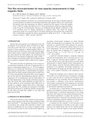
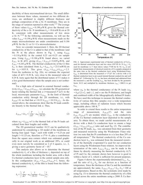
FIG. 4. Approximate experimental ratio <strong>of</strong> <strong>the</strong>rmal conductivity <strong>of</strong> Cu k Cu<br />
used for <strong>the</strong>rmal conduction layer and low stress LPCVD Si–N k SiNx k m<br />
used for membrane vs T. Inset shows values *100 for Si–N. k Cu is estimated<br />
from measurements <strong>of</strong> electrical resistivity <strong>of</strong> Cu samples prepared at<br />
<strong>the</strong> same time as <strong>the</strong> <strong>the</strong>rmal conduction layer us<strong>in</strong>g Wiedemann-Franz,<br />
k SiNx is determ<strong>in</strong>ed from <strong>the</strong> measured P/T for a device with a Cu<br />
<strong>the</strong>rmal conduction layer to give good <strong>in</strong>temal <strong>the</strong>rmal conductivity and well<br />
def<strong>in</strong>ed T. Follow<strong>in</strong>g Eq. 2, Pt has been calculated and subtracted from<br />
<strong>the</strong> measured , and <strong>the</strong> result<strong>in</strong>g SiNx has been divided by <strong>the</strong> geometric<br />
factor 10.33 and multiplied by membrane thickness t SiNx 1800 Å to get<br />
k SiNx .<br />
where Pt is <strong>the</strong> <strong>the</strong>rmal conductance <strong>of</strong> <strong>the</strong> Pt leads ( Pt<br />
k Pt t/Lw, and t, L, and w are <strong>the</strong> Pt thickness, and length<br />
and comb<strong>in</strong>ed width <strong>of</strong> <strong>the</strong> lithographically def<strong>in</strong>ed Pt leads.<br />
We have used this technique to measure <strong>the</strong> <strong>the</strong>rmal conductivity<br />
<strong>of</strong> various th<strong>in</strong> film samples over a wide temperature<br />
range, <strong>in</strong>clud<strong>in</strong>g effects <strong>of</strong> radiation losses which become<br />
appreciable above 100 K. 15<br />
In order to extend <strong>the</strong>se results to <strong>the</strong> entire temperature<br />
range <strong>of</strong> measurement, k 2D,m (T) and <strong>the</strong> ratio<br />
k 2D,s /k 2D,m (T) are needed, where k 2D,s is <strong>the</strong> conductivity<br />
<strong>of</strong> <strong>the</strong> Cu <strong>the</strong>rmal conduction layer deposited <strong>in</strong> <strong>the</strong> sample<br />
area. To obta<strong>in</strong> <strong>the</strong>se, we made careful measurements <strong>of</strong> a<br />
device with a thick Cu conduction layer to ensure a large<br />
(k 2D,s k 2D,m )/k 2D,m ) ratio and used Eq. 2. The contribution<br />
<strong>of</strong> <strong>the</strong> Pt leads, Pt , was calculated from <strong>the</strong>ir geometry<br />
and measured resistivity us<strong>in</strong>g <strong>the</strong> Wiedemann–Franz relation<br />
we note that <strong>the</strong> Pt contribution to is less than 20% at<br />
all temperatures. 15 The <strong>the</strong>rmal conductivity <strong>of</strong> <strong>the</strong> Cu conduction<br />
layer k Cu was estimated from <strong>the</strong> measured resistivity<br />
<strong>of</strong> <strong>the</strong> <strong>the</strong>rmally evaporated Cu used for our conduction<br />
layers us<strong>in</strong>g <strong>the</strong> Wiedemann-Franz relation. An improved determ<strong>in</strong>ation<br />
<strong>of</strong> <strong>the</strong> ratio k 2D,Cu /k 2D,m can be made <strong>in</strong> <strong>the</strong><br />
future by directly measur<strong>in</strong>g <strong>the</strong> <strong>the</strong>rmal conductivity k(T)<br />
<strong>of</strong> Pt and Cu; <strong>the</strong> estimate shown here however is good to<br />
with<strong>in</strong> a factor <strong>of</strong> 2, which is sufficient for present purposes.<br />
Figure 4 shows <strong>the</strong> experimentally-determ<strong>in</strong>ed k Cu , k m ,<br />
and <strong>the</strong> ratio <strong>of</strong> k Cu /k m for our devices as a function <strong>of</strong><br />
temperature. S<strong>in</strong>ce <strong>the</strong> thickness <strong>of</strong> <strong>the</strong> Cu and <strong>the</strong> membrane<br />
are approximately <strong>the</strong> same, k 2D,Cu /k 2D,m k Cu /k m 100 at<br />
all temperatures. Based on this, <strong>the</strong> systematic error made by<br />
us<strong>in</strong>g Eq. 3 to determ<strong>in</strong>e <strong>the</strong> <strong>the</strong>rmal conductivity <strong>of</strong> a film<br />
placed across <strong>the</strong> entire membrane us<strong>in</strong>g a 2000 Å Cu <strong>the</strong>r-<br />
Downloaded 13 Jun 2005 to 128.32.228.151. Redistribution subject to AIP license or copyright, see http://rsi.aip.org/rsi/copyright.jsp