

Journal of the Royal Naval Scientific Service. Volume 29, Number 6 ...
Journal of the Royal Naval Scientific Service. Volume 29, Number 6 ...
Journal of the Royal Naval Scientific Service. Volume 29, Number 6 ...

You also want an ePaper? Increase the reach of your titles
YUMPU automatically turns print PDFs into web optimized ePapers that Google loves.
signal-paths leading to <strong>the</strong> faulty unit or on<br />
signal-paths unaffected by <strong>the</strong> fault in o<strong>the</strong>r<br />
parts <strong>of</strong> <strong>the</strong> equipment.<br />
If a new fault is given to <strong>the</strong> trains it will<br />
<strong>the</strong>n be necessary to change <strong>the</strong> colour <strong>of</strong> <strong>the</strong><br />
light at certain test-points and for practical<br />
purposes this needs to be done quickly. To do<br />
this, one must change <strong>the</strong> colour <strong>of</strong> <strong>the</strong> light<br />
entering <strong>the</strong> light-guide, <strong>the</strong> tip <strong>of</strong> which is<br />
visible to <strong>the</strong> trainee at <strong>the</strong> test-point. The<br />
light for each light-guide is provided by a lightbulb<br />
which is switched on when <strong>the</strong> trainee<br />
touches <strong>the</strong> test-point with <strong>the</strong> probe. Between<br />
<strong>the</strong> receiving end <strong>of</strong> <strong>the</strong> light-guide and <strong>the</strong> bulb<br />
is a transparent filter mounted on a solenoid.<br />
The top half <strong>of</strong> <strong>the</strong> filter is red and <strong>the</strong> bottom<br />
half is green; <strong>the</strong> green part <strong>of</strong> <strong>the</strong> filter is<br />
opposite <strong>the</strong> light-guide when <strong>the</strong> solenoid is<br />
open. When <strong>the</strong> solenoid is closed, <strong>the</strong> red part<br />
<strong>of</strong> <strong>the</strong> filter is pulled down opposite <strong>the</strong> lightguide.<br />
A programme card is inserted nto <strong>the</strong><br />
device to close <strong>the</strong> solenoids for those testpoints<br />
where <strong>the</strong> light must be charged. A<br />
separate programme card must thus be prepared<br />
for each fault.<br />
The simplified test-point data is provided to<br />
allow <strong>the</strong> trainee to concentrate on <strong>the</strong> logical<br />
aspects <strong>of</strong> check-out. When <strong>the</strong> trainee's logic<br />
meets <strong>the</strong> required training standard he will<br />
<strong>the</strong>n be required to perform his check-out with<br />
waveform data.<br />
(b) Waveform Interpretation<br />
(i)T/ie Carousel Slide Projector (Fig. 3)<br />
Photographs were taken <strong>of</strong> wavefoims on<br />
an oscilloscope which was connected, in turn,<br />
to each test-point in <strong>the</strong> JDA radar display.<br />
These were <strong>the</strong>n made into slides for presentation<br />
by <strong>the</strong> Carousel slide projector (randomaccess<br />
model). When a test-point is touched<br />
with <strong>the</strong> probe, a binary code is sent to <strong>the</strong><br />
Carousel projector which <strong>the</strong>n automatically<br />
hunts <strong>the</strong> appropriate slide and projects it on<br />
a screen. The trainee must <strong>the</strong>n compare <strong>the</strong><br />
picture with that given in a waveform handbook.<br />
The storage capacity <strong>of</strong> <strong>the</strong> slide holder is<br />
limited, however, to a maximum <strong>of</strong> 80 slides<br />
so that this device might not be suitable for<br />
large equipments with more than 80 testpoints.<br />
However, <strong>the</strong> storage capacity is probably<br />
adequate for smaller equipments and if<br />
<strong>the</strong> equipment is large, it might be possible to<br />
limit <strong>the</strong> number <strong>of</strong> test-points by including<br />
only those which are important. Where I his is<br />
Fault Finding: Cunningham and Hum 269<br />
not possible (as in a complex multi-equipment<br />
system) a projector with a much larger storage<br />
would be needed. This is provided by <strong>the</strong> Marconi<br />
Automated Micr<strong>of</strong>orm Terminal.<br />
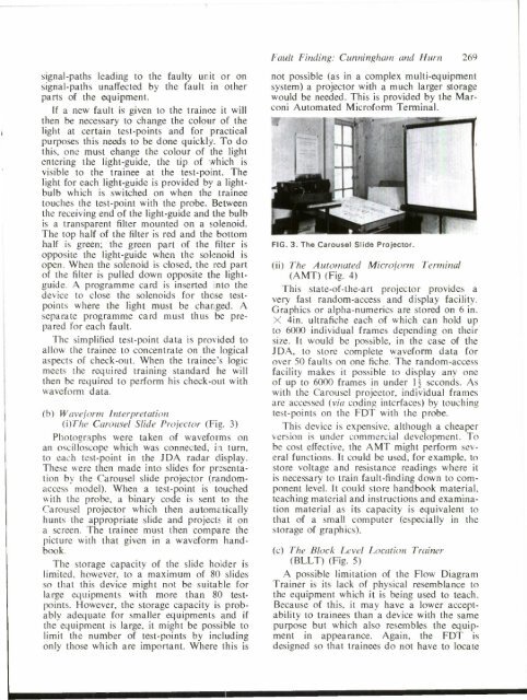
FIG. 3. The Carousel Slide Projector.<br />
(ii) The Automated Micr<strong>of</strong>orm Terminal<br />
(AMT) (Fig. 4)<br />
This state-<strong>of</strong>-<strong>the</strong>-art projector provides a<br />
very fast random-access and display facility.<br />
Graphics or alpha-numerics are stored on 6 in.<br />
X 4in. ultrafiche each <strong>of</strong> which can hold up<br />
to 6000 individual frames depending on <strong>the</strong>ir<br />
size. It would be possible, in <strong>the</strong> case <strong>of</strong> <strong>the</strong><br />
JDA, to store complete waveform data for<br />
over 50 faults on one fiche. The random-access<br />
facility makes it possible to display any one<br />
<strong>of</strong> up to 6000 frames in under 1£ seconds. As<br />
with <strong>the</strong> Carousel projector, individual frames<br />
are accessed (via coding interfaces) by touching<br />
test-points on <strong>the</strong> FDT with <strong>the</strong> probe.<br />
This device is expensive, although a cheaper<br />
version is under commercial development. To<br />
be cost effective, <strong>the</strong> AMT might perform several<br />
functions. It could be used, for example, to<br />
store voltage and resistance readings where it<br />
is necessary to train fault-finding down to component<br />
level. It could store handbook material,<br />
teaching material and instructions and examination<br />
material as its capacity is equivalent to<br />
that <strong>of</strong> a small computer (especially in <strong>the</strong><br />
storage <strong>of</strong> graphics).<br />
(c) The Block Level Location Trainer<br />
(BLLT) (Fig. 5)<br />
A possible limitation <strong>of</strong> <strong>the</strong> Flow Diagram<br />
Trainer is its lack <strong>of</strong> physical resemblance to<br />
<strong>the</strong> equipment which it is being used to teach.<br />
Because <strong>of</strong> this, it may have a lower acceptability<br />
to trainees than a device with <strong>the</strong> same<br />
purpose but which also resembles <strong>the</strong> equipment<br />
in appearance. Again, <strong>the</strong> FDT is<br />
designed so that trainees do not have to locate


