

Journal of the Royal Naval Scientific Service. Volume 29, Number 6 ...
Journal of the Royal Naval Scientific Service. Volume 29, Number 6 ...
Journal of the Royal Naval Scientific Service. Volume 29, Number 6 ...

You also want an ePaper? Increase the reach of your titles
YUMPU automatically turns print PDFs into web optimized ePapers that Google loves.
270 J.R.N.S.S., Vol. <strong>29</strong>, No. 6<br />
FIG. 4. The Automated Micr<strong>of</strong>orm Terminal.<br />
test-points on <strong>the</strong> equipment but it may be<br />
necessary to give practice at this. The BLLT<br />
was designed to meet <strong>the</strong>se possible limitations.<br />
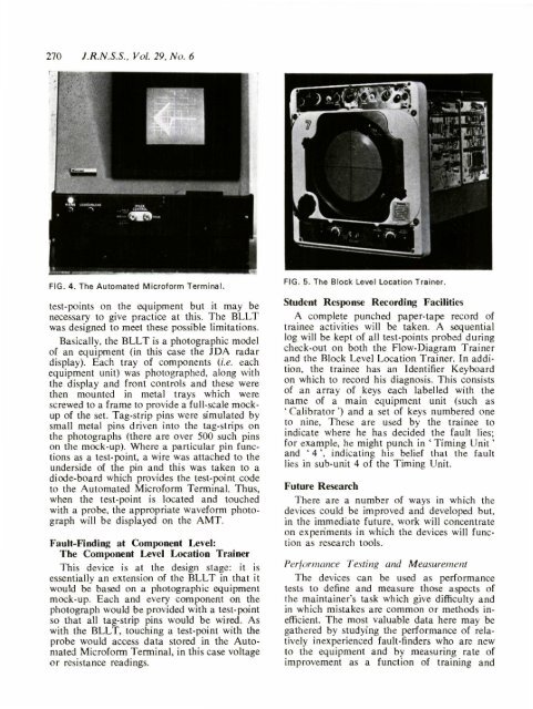
Basically, <strong>the</strong> BLLT is a photographic model<br />
<strong>of</strong> an equipment (in this case <strong>the</strong> JDA radar<br />
display). Each tray <strong>of</strong> components (i.e. each<br />
equipment unit) was photographed, along with<br />
<strong>the</strong> display and front controls and <strong>the</strong>se were<br />
<strong>the</strong>n mounted in metal trays which were<br />
screwed to a frame to provide a full-scale mockup<br />
<strong>of</strong> <strong>the</strong> set. Tag-strip pins were simulated by<br />
small metal pins driven into <strong>the</strong> tag-strips on<br />
<strong>the</strong> photographs (<strong>the</strong>re are over 500 such pins<br />
on <strong>the</strong> mock-up). Where a particular pin functions<br />
as a test-point, a wire was attached to <strong>the</strong><br />
underside <strong>of</strong> <strong>the</strong> pin and this was taken to a<br />
diode-board which provides <strong>the</strong> test-point code<br />
to <strong>the</strong> Automated Micr<strong>of</strong>orm Terminal. Thus,<br />
when <strong>the</strong> test-point is located and touched<br />
with a probe, <strong>the</strong> appropriate waveform photograph<br />
will be displayed on <strong>the</strong> AMT.<br />
Fault-Finding at Component Level:<br />
The Component Level Location Trainer<br />
This device is at <strong>the</strong> design stage: it is<br />
essentially an extension <strong>of</strong> <strong>the</strong> BLLT in that it<br />
would be based on a photographic equipment<br />
mock-up. Each and every component on <strong>the</strong><br />
photograph would be provided with a test-point<br />
so that all tag-strip pins would be wired. As<br />
with <strong>the</strong> BLLT, touching a test-point with <strong>the</strong><br />
probe would access data stored in <strong>the</strong> Automated<br />
Micr<strong>of</strong>orm Terminal, in this case voltage<br />
or resistance readings.<br />
FIG. 5. The Block Level Location Trainer.<br />
Student Response Recording Facilities<br />
A complete punched paper-tape record <strong>of</strong><br />
trainee activities will be taken. A sequential<br />
log will be kept <strong>of</strong> all test-points probed during<br />
check-out on both <strong>the</strong> Flow-Diagram Trainer<br />
and <strong>the</strong> Block Level Location Trainer. In addition,<br />
<strong>the</strong> trainee has an Identifier Keyboard<br />
on which to record his diagnosis. This consists<br />
<strong>of</strong> an array <strong>of</strong> keys each labelled with <strong>the</strong><br />
name <strong>of</strong> a main equipment unit (such as<br />
' Calibrator') and a set <strong>of</strong> keys numbered one<br />
to nine, These are used by <strong>the</strong> trainee to<br />
indicate where he has decided <strong>the</strong> fault lies;<br />
for example, he might punch in ' Timing Unit'<br />
and ' 4', indicating his belief that <strong>the</strong> fault<br />
lies in sub-unit 4 <strong>of</strong> <strong>the</strong> Timing Unit.<br />
Future Research<br />
There are a number <strong>of</strong> ways in which <strong>the</strong><br />
devices could be improved and developed but,<br />
in <strong>the</strong> immediate future, work will concentrate<br />
on experiments in which <strong>the</strong> devices will function<br />
as research tools.<br />
Performance Testing and Measurement<br />
The devices can be used as performance<br />
tests to define and measure those aspects <strong>of</strong><br />
<strong>the</strong> maintainer's task which give difficulty and<br />
in which mistakes are common or methods inefficient.<br />
The most valuable data here may be<br />
ga<strong>the</strong>red by studying <strong>the</strong> performance <strong>of</strong> relatively<br />
inexperienced fault-finders who are new<br />
to <strong>the</strong> equipment and by measuring rate <strong>of</strong><br />
improvement as a function <strong>of</strong> training and


