8120/8084 Addendum - Navman Marine
8120/8084 Addendum - Navman Marine
8120/8084 Addendum - Navman Marine

You also want an ePaper? Increase the reach of your titles
YUMPU automatically turns print PDFs into web optimized ePapers that Google loves.
<strong>Navman</strong><br />
<strong>8120</strong>/<strong>8084</strong><br />
Fuel, AIS, & Radar<br />
<strong>Addendum</strong> 06/07<br />
w w w . n a v m a n . c o m
Warning<br />
AIS: The AIS features on this chart-plotter are designed as a safety aid only and do not<br />
guarantee safety at sea. AIS transmission is mandatory on some, but not all, vessels. AIS<br />
should be used to complement radar, but AIS is not a substitute for radar.<br />
Notes<br />
• AIS and Radar functions require optional accessories to be installed.<br />
• Radar is available in 2 kW, 4 kW, 6 kW units.<br />
• The setup menu can be opened by pressing twice (<strong>8084</strong>) /<br />
(<strong>8120</strong>) then select System:<br />
Sonar<br />
Disable any sonar transducer and disable sonar functions.<br />
A sonar transducer is fitted. Enable sonar operation.<br />
Radar<br />
No appropriate Radar system is fitted. Disable RADAR.<br />
An appropriate Radar receiver is fitted.<br />
Enable Radar.<br />
AIS<br />
No appropriate AIS receiver is fitted. Disable AIS.<br />
An appropriate AIS receiver is fitted.<br />
Enable AIS.<br />
Appendix<br />
<strong>8084</strong> Size: 190 mm (7.48“) H x 285 mm (11.22“) W x 76.8 mm (3.02“) D. Allow 3 mm<br />
clearance on each side for dust cover.<br />
<strong>8084</strong> Display: 213.4 mm (8.4”) diagonal, TFT color, 800 x 600 pixels.<br />
CPA - Closest Point of Approach. The closest distance two vessels will come to each<br />
other based on their current course and speed.<br />
Radar guard zone - An area around the boat, set up by the operator and defined by<br />
distance and bearing. If an object (e.g. another boat) enters the radar guard zone, an<br />
alarm is activated.<br />
Rain clutter - Heavy rain or snow can cause interference with the radar image.<br />
Range (radar) - The distance between the centre of the radar image and the outer range<br />
ring. The scale is shown in the top left corner of the radar window.<br />
Range rings - Concentric circles extending from your boat (usually at the centre of the<br />
radar window) and used to estimate distances to objects. The scale is shown in the top<br />
left corner of the radar window.<br />
Route - Two or more waypoints linked in sequence to form a course for the boat.<br />
Sea clutter - Rough seas can cause interference with the radar image.<br />
2<br />
NAVMAN <strong>8120</strong>/<strong>8084</strong> Fuel, AIS, & Radar <strong>Addendum</strong>
Fuel functions and display<br />
What the fuel computer does<br />
! CAUTION<br />
! WARNING<br />
To ensure the fuel data is accurate:<br />
DANGER<br />
When you add or remove fuel from a tank, tell the <strong>8120</strong>/<strong>8084</strong>.<br />
If the boat has petrol/gasoline sensors, calibrate them during installation or if the fuel<br />
CAUTION<br />
readings seem inaccurate.<br />
Choose an appropriate type of boat speed sensor or GPS source to calculate economy,<br />
range and the fuel consumption curve.<br />
If the boat uses a paddlewheel sensor to measure speed, calibrate it during installation or<br />
if the speed readings seem inaccurate.<br />
Low fuel alarm<br />
To set a low fuel alarm for a tank:<br />
1 Press twice, select Fuel, then select<br />
Setup tanks.<br />
2 On a multi-tank boat, select the tank to set<br />
the alarm for.<br />
3 Select Tank alarm and enter a fuel level<br />
to trigger the low fuel alarm; or enter zero<br />
to disable the alarm.<br />
Boat speed sensors<br />
Selecting a boat speed sensor<br />
The fuel calculations can use boat speeds<br />
from the GPS, or from a paddlewheel sensor<br />
or pitot sensor if these optional sensors are<br />
installed:<br />
Paddlewheel and pitot sensors measure<br />
the speed through the water; GPS speed is<br />
speed over ground; these sensors can give<br />
different values for Range, Economy and<br />
the fuel consumption curves.<br />
A pitot sensor is more accurate than a<br />
paddlewheel sensor at high speeds but is<br />
not accurate at low speeds. A paddlewheel<br />
sensor is more accurate than a pitot sensor<br />
at low speeds.<br />
When a low fuel alarm is set, the alarm’s fuel<br />
level is shown on the fuel display tank levels<br />
as a red bar. The alarm can also be set using<br />
the Alarms setup menu.<br />
To select an optional speed sensor<br />
1 Press twice, select Fuel, then select<br />
Speed source.<br />
2 To use a paddlewheel or pitot sensor,<br />
select Water speed, otherwise select<br />
Ground speed to use GPS speed.<br />
3 If you selected Water speed and you have<br />
both a paddlewheel sensor and a pitot<br />
sensor:<br />
i Press , select SmartCraft and<br />
select Speed type<br />
ii Select Paddlewheel or Pitot.<br />
Tip: You can select a different speed<br />
sensor during a trip.<br />
NAVMAN <strong>8120</strong>/<strong>8084</strong> Fuel, AIS, & Radar <strong>Addendum</strong> 3
Water speed and ground speed<br />
A paddlewheel sensor and a pitot sensor<br />
measure water speed, the boat speed<br />
through the water. A GPS measures ground<br />
speed, the boat speed over the bottom of<br />
the water. If there is a current, then these<br />
speeds will be different, and the log, trip<br />
log, economy and range will be different, as<br />
shown below.<br />
Water speed is better for measuring the<br />
boat’s potential performance, Ground speed<br />
is better for going to a destination because it<br />
takes currents into account.<br />
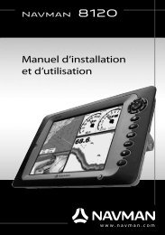
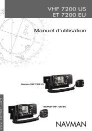
When the current is from ahead, ground speed is less than water speed<br />
Water speed 10 knots<br />
Water speed 10 knots<br />
Current 4 knots<br />
Gives a ground speed of 6 knots<br />
Gives a ground speed<br />
of about 8 knots Current 4 knots at 45º<br />
For this example:<br />
If the boat travels for one hour, uses 3 gallons of fuel per hour and has 50<br />
gallons of fuel left:<br />
Speed Log Economy Range<br />
Using water speed: 10 knots 10 nm 3.3 nm / gal 165 nm<br />
Using ground speed: 6 knots 6 nm 2.0 nm / gal 100 nm<br />
When the current is from behind, ground speed is more than water speed<br />
Water speed 10 knots<br />
Current<br />
4 knots<br />
Water speed 10 knots<br />
Current 4<br />
knots at 45º<br />
Gives a ground speed of 14 knots<br />
Gives a ground speed of about 13 knots<br />
For this example:<br />
If the boat travels for one hour, uses 3 gallons of fuel and has 50 gallons of fuel left:<br />
Speed Log Economy Range<br />
Using water speed: 10 knots 10 nm 3.3 nm / gal 165 nm<br />
Using ground speed: 14 knots 14 nm 4.7 nm / gal 235 nm<br />
4<br />
NAVMAN <strong>8120</strong>/<strong>8084</strong> Fuel, AIS, & Radar <strong>Addendum</strong>
Calibration<br />
Calibrate petrol/gasoline fuel flow<br />
sensors during installation, or if the fuel<br />
readings seem inaccurate and the other<br />
troubleshooting suggestions do not help.<br />
Note<br />
SmartCraft fuel sensors and NAVMAN<br />
diesel sensors are factory calibrated and<br />
should never need recalibrating.<br />
On a multi engine boat, calibrate each<br />
engine’s sensor. This can be done at the<br />
same time with a portable tank for each<br />
engine or at different times using one<br />
portable tank.<br />
Calibrating a sensor requires accurate<br />
measurement of the fuel consumption.<br />
This is best done using a small portable<br />
tank. At least 4 gallons (15 litres) of fuel<br />
should be used to ensure an accurate<br />
calibration.<br />
It is often very difficult to fill underfloor<br />
tanks to the same level twice due to air<br />
pockets, so the more fuel used, the more<br />
accurate the calibration.<br />
To calibrate the sensor(s):<br />
1 Record the level of the fuel in the tank(s).<br />
2 Connect the portable tank(s) to the engine<br />
through the fuel sensor(s).<br />
3 Run the engine at normal cruising speed<br />
until at least 4 gallons (15 litres) of fuel has<br />
been used per engine.<br />
4 Check the actual amount of fuel used per<br />
engine by refilling the portable tank(s) to<br />
the original level and noting the reading(s)<br />
of the fuel dispenser’s gauge.<br />
5 Press twice, select Fuel, then select<br />
Setup engines.<br />
6 On a single engine boat, select<br />
Calibrate and change the displayed<br />
value to be equal to the reading of the fuel<br />
dispenser’s gauge, then press .<br />
On a multi-engine boat select the engine.<br />
Select Calibrate and change the<br />
displayed value to be equal to the reading<br />
of the fuel dispenser’s gauge, then press<br />
. Repeat for the other engines.<br />
NAVMAN <strong>8120</strong>/<strong>8084</strong> Fuel, AIS, & Radar <strong>Addendum</strong> 5
AIS<br />
AIS is short for Automatic Identification<br />
System. The International Convention<br />
for Safety of Life At Sea (SOLAS) requires<br />
all vessels greater than 300 tons and all<br />
passenger vessels to be equipped with AIS<br />
Transponders. All vessels equipped with<br />
AIS permanently broadcast via one or more<br />
of the two dedicated VHF channels. This<br />
transmission may include information about<br />
the vessels MMSI-number, its call sign, name,<br />
position, course, heading, speed, rate of turn<br />
and type of vessel.<br />
This unit can receive and display AIS<br />
information when connected to an AIS<br />
receiver. Available AIS vessels transmitting in<br />
the local area are shown on the chart when<br />
this feature is enabled.<br />
The following AIS receivers are supported by<br />
this unit:<br />
• Comar SLR200 (external GPS).<br />
• Weatherdock Two Channel AIS Receiver<br />
“EASY AIS”, Part No. 5-A-013 (external GPS).<br />
• NASA <strong>Marine</strong> AIS Engine 2 channel<br />
MultiPlex Receiver (external GPS).<br />
Other AIS receivers may work but have not<br />
been tested with this unit.<br />
To enable AIS from the system menu check<br />
the AIS box.<br />
Viewing AIS Vessels<br />
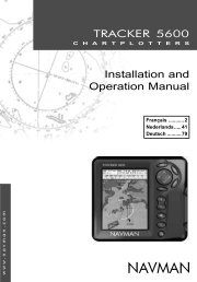
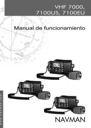
A typical AIS window shows:<br />
E<br />
B<br />
A<br />
C<br />
6<br />
A AIS Vessel<br />
B Dangerous Vessel<br />
C Projected Course<br />
D Data Box<br />
E Range Rings<br />
NAVMAN <strong>8120</strong>/<strong>8084</strong> Fuel, AIS, & Radar <strong>Addendum</strong>
When the cursor is placed over an AIS<br />
vessel for at least two seconds, a data box<br />
appears at the bottom of the window with<br />
information about the AIS vessel.<br />
For complete AIS information of the AIS<br />
vessel place the cursor over an AIS vessel for<br />
at least two seconds and press .<br />
Press either or to clear the<br />
information.<br />
Dangerous Vessels<br />
The <strong>8120</strong>/<strong>8084</strong> calculates the time of closest<br />
point of approach (TCPA) and closest point of<br />
approach (CPA) for each AIS vessel.<br />
This is used to determine potential dangerous<br />
vessels. If the TCPA and the CPA is below<br />
the trigger values then it will be considered<br />
dangerous.<br />
A dangerous vessel is indicated on the chart<br />
by a red circle around the icon.<br />
TCPA 15 min<br />
CPA 0.5 nm<br />
AIS Windows<br />
To go to the AIS windows, press , select<br />
More, select AIS, then press or to select<br />
one of the two windows: Vessels or Safety<br />
msgs (rx).<br />
If there are more items than will fit on the<br />
window, press or to see the others.<br />
Vessels<br />
This is a sorted list of vessels currently being<br />
received by the AIS receiver. The maximum<br />
number of vessels that the system will<br />
support is 250. Once maximum is reached,<br />
vessels furthest away from the current<br />
location will be replaced. A vessel will be<br />
removed from the list if no information is<br />
received within 6 minutes from the last<br />
message.<br />
Displaying an AIS vessel on the chart<br />
1 Press or to select a vessel.<br />
2 Press and select Display. The<br />
Instrument switches to chart window, with<br />
the selected vessel position in the middle.<br />
Displaying Full AIS Details<br />
1 Press or to select a vessel.<br />
2 Press and select More Info or<br />
press .<br />
NAVMAN <strong>8120</strong>/<strong>8084</strong> Fuel, AIS, & Radar <strong>Addendum</strong> 7
Displaying Full AIS Details<br />
1 Press or to select a vessel.<br />
2 Press and select More Info or<br />
press .<br />
This window displays all information for<br />
the selected AIS vessel provided by the AIS<br />
receiver.<br />
Sorting Vessels<br />
Press , select Sort and select one of<br />
the options.<br />
This sorts the list based on the chosen<br />
category.<br />
Safety msgs (rx)<br />
Safety msgs (rx) are broadcasted messages<br />
received by the AIS receiver. This window<br />
displays the date and time of message<br />
received, MMSI of AIS vessel that broadcasted<br />
the message, and the message itself. Safety<br />
msgs (rx) list will store up to 10 messages.<br />
The oldest message is replaced when the list<br />
is full.<br />
Note: This feature requires an AIS receiver.<br />
There are multiple methods to filter AIS<br />
vessels that are displayed onto the charts.<br />
Filter by Type<br />
Vessel types that are not selected will be<br />
filtered off the chart. Default is set to all types<br />
enabled allowing all vessels to be displayed<br />
on the chart.<br />
Filter by distance<br />
Vessels outside the radius selected from our<br />
current position are filtered off the chart.<br />
Default value is set to 300 nm allowing all<br />
vessels to be displayed on the chart within<br />
that distance.<br />
Filter by speed<br />
Vessels with speed below the value selected<br />
are filtered off the charts. Default is set to 0<br />
nm allowing all vessels to be displayed onto<br />
the chart.<br />
Show Dangerous Only<br />
Show only vessels that have a TCPA/CPA<br />
below the trigger values. This filter will<br />
override any other filter option.<br />
Dangerous Vessel Alarm<br />
When enabled an alarm will activate when<br />
both the TCPA and CPA are less than the<br />
trigger values.<br />
Note: Even when this setting is disabled the<br />
dangerous vessels will still be indicated on<br />
the chart.<br />
TCPA Limit<br />
Set the Time of Closet Point of Approach<br />
limit.<br />
CPA Limit<br />
Set the Closet Point of Approach limit.<br />
Projected Course<br />
Show the estimated course of all vessels<br />
based on their current SOG and COG.<br />
Range Rings<br />
Show a selectable number of range rings<br />
around the boat. The rings are drawn in<br />
multiples of the current chart scale.<br />
Proximity Alarm<br />
When enabled an alarm will activate when<br />
any AIS vessel is within the proximity alarm<br />
radius.<br />
8<br />
NAVMAN <strong>8120</strong>/<strong>8084</strong> Fuel, AIS, & Radar <strong>Addendum</strong>
Radar<br />
Radar is the Radio Detection And Ranging<br />
system. Radar functions require an optional<br />
NAVMAN radar system to be installed. Three<br />
radar systems are available; 2 kW, 4 kW, or<br />
6 kW.<br />
When the radar is operating, the scanner<br />
transmits powerful microwave radio pulses<br />
which are reflected back from any solid<br />
objects such as land masses or other boats.<br />
These objects are called targets and are<br />
shown on the radar window.<br />
The scanner rotates through 360° so the<br />
radar window shows all of the area around<br />
your boat within the range of the scanner,<br />
producing a map-like display called the PPI<br />
(Plan Position Indicator).<br />
Typically, your boat is in the centre of the<br />
radar window with concentric range rings<br />
surrounding it. The range rings help you<br />
to quickly estimate the distance to various<br />
targets.<br />
You can also view the radar overlaid on the<br />
chart screen.<br />
Radar window<br />
A<br />
K<br />
B<br />
C<br />
D<br />
G<br />
H<br />
I<br />
J<br />
L<br />
M<br />
E<br />
F<br />
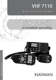
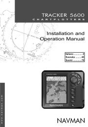
The radar window shows:<br />
A Distance between each range ring (in this<br />
example, 1/8 nautical mile)<br />
B Range of radar (in this example, shown in<br />
large digits)<br />
C Radar rotation (in this example, North Up)<br />
D Radar motion mode (in this example,<br />
Relative Mode)<br />
E Cursor<br />
F Distance and bearing to the cursor from<br />
the vessel position<br />
G Compass ring<br />
H Range ring<br />
I North line (blue)<br />
J Heading line (white)<br />
K The bearing (in Relative, True, or Magnetic<br />
mode)<br />
L Echo Expansion setting<br />
M Interference Rejection setting<br />
NAVMAN <strong>8120</strong>/<strong>8084</strong> Fuel, AIS, & Radar <strong>Addendum</strong> 9
Radar modes<br />
There are four radar modes:<br />
• Disabled. This saves on power<br />
consumption and magnetron usage. If the<br />
radar is disabled, it has to warm up and<br />
enter standby mode before it can start<br />
transmitting.<br />
• Warming. The radar on and is warming up.<br />
This can take up to 90 seconds, depending<br />
on your scanner type.<br />
• Standby. The radar is on and is warmed<br />
up. It is ready to start transmitting<br />
immediately.<br />
• Transmitting. The radar is actively sending<br />
and receiving microwave radio pulses. An<br />
open array will be rotating.<br />
If you want to save on power but be able to<br />
start transmitting immediately, use standby<br />
mode.<br />
Enabling the radar functionality<br />
When the radar is enabled, it will turn on,<br />
warm up, and enter standby mode.<br />
To enable the radar functionality:<br />
1 Press twice to display the Setup<br />
menu, then select System.<br />
2 Set Radar to .<br />
3 The radar immediately turns on and enters<br />
warm-up mode. A message shows how<br />
long this will take.<br />
4 When the warm-up period is complete,<br />
the radar enters standby mode and is<br />
ready to transmit.<br />
Selecting standby mode or transmit mode<br />
You can quickly change between these two<br />
modes.<br />
1. From the radar window, press and<br />
set the Transmit option to (transmit<br />
mode) or (standby mode).<br />
Disabling the radar functionality<br />
1 Press twice to display the Setup<br />
menu, then select System.<br />
2 Set Radar to .<br />
3 A warning message appears. If you are<br />
sure that you want to disable the radar<br />
functionality, select Yes.<br />
4 The radar enters disabled mode<br />
immediately.<br />
Radar Chart Overlay<br />
If you have a radar installed, you can overlay<br />
the radar screen on your chart screen. This is<br />
extremely useful because it can help you to:<br />
• interpret the radar image by matching the<br />
radar targets with charted objects<br />
• quickly identify objects that are not on the<br />
chart, such as other boats<br />
The radar overlay is also very useful in<br />
conditions of reduced visibility, at night, or in<br />
busy or hazardous waters.<br />
10<br />
NAVMAN <strong>8120</strong>/<strong>8084</strong> Fuel, AIS, & Radar <strong>Addendum</strong><br />
To turn the radar overlay on or off:<br />
From the chart window, press and set<br />
Radar Overlay option to or .<br />
An extra menu item will them be displayed to<br />
control the radar and overlay.<br />
Overlay Palette<br />
The color of the radar overlay can be<br />
changed, to improve chart/ radar data
separation or take into account viewing<br />
conditions.<br />
1 Press MENU twice.<br />
2 Select Radar.<br />
3 Select Overlay palette.<br />
4 Select your color preference.<br />
Overlay Transparency<br />
The transparency of the radar overlay can be<br />
adjusted, in case it obscures important chart<br />
features.<br />
1 From the chart screen or pane, press MENU<br />
once.<br />
Adjusting the quality of the radar window<br />
Common problems that can degrade the<br />
quality of the radar window include:<br />
• sea clutter<br />
• rain clutter<br />
• false echoes (sometimes called ghost<br />
echoes) and background noise<br />
• side lobe patterns (false echoes that appear<br />
as an arc or a broken arc)<br />
• shadows (blind spots)<br />
• multiple echoes off the same object<br />
• incorrect threshold setting<br />
If the radar is installed at a suitable height and<br />
in a suitable location on your boat, side lobe<br />
patterns and shadows (blind spots) caused<br />
by obstructions such as funnels or masts will<br />
be minimized. If you are having problems<br />
with these, you may need to relocate the<br />
scanner. Consult the Installation Guide for<br />
your NAVMAN scanner or talk to your dealer or<br />
installer.<br />
Multiple echoes off the same object are<br />
most likely to occur when you are close to a<br />
large target and are usually only a temporary<br />
nuisance.<br />
You can adjust the radar to reduce the effects<br />
of sea clutter, rain clutter, and interference<br />
from other radars. You can also change the<br />
gain mode setting and the gain level setting to<br />
help reduce false echoes.<br />
From the radar window, press then<br />
select Adjust Radar and press .<br />
2 Select Radar overlay. If the box is<br />
unchecked, press ENTER . A Radar menu<br />
option appears below.<br />
3 Select Radar.<br />
4 Select Transparency.<br />
5 Adjust the slider to suit. Changes are seen<br />
on the chart in real time.<br />
Also available on the Radar overlay<br />
menu are shortcuts to enable/disable radar<br />
transmission (Transmit, see Manual,<br />
18-4) and to access the radar setup options<br />
(Adjust radar, see manual, 18-6).<br />
Changing the gain mode<br />
Use the radar gain mode to specify whether<br />
you want to adjust the radar gain yourself or<br />
have it adjusted automatically.<br />
To change the radar gain mode:<br />
1 From the radar window, press then<br />
select Adjust Radar.<br />
2 Select Gain Mode. There are three<br />
choices:<br />
• Manual. Adjust the radar gain yourself<br />
to suit your local conditions and<br />
preferences.<br />
• Auto. The radar gain is adjusted<br />
automatically.<br />
• Range rider. Select this to adjust the<br />
radar gain yourself for a particular radar<br />
range, then have these settings stored<br />
and automatically re-used whenever<br />
you operate at that range again.<br />
NAVMAN <strong>8120</strong>/<strong>8084</strong> Fuel, AIS, & Radar <strong>Addendum</strong> 11
Changing the gain level<br />
Use the radar gain level to adjust the sensitivity<br />
of the radar receiver. Ideally, the radar gain<br />
level should be set so that background noise is<br />
just visible on the radar window.<br />
If the radar gain level is too low, weak echoes<br />
won’t be shown. If the radar gain level is too<br />
high, strong echoes will be difficult to see<br />
amongst the large amount of background<br />
noise.<br />
(If the radar Gain Mode is set to Auto and you<br />
adjust the gain level manually, the Gain Mode<br />
is changed to Manual.)<br />
To change the radar gain level:<br />
1 From the radar window, press then<br />
select Adjust Radar.<br />
2 Select Gain Level then use and<br />
to decrease or increase the setting.<br />
Changing the sea clutter mode (Manual<br />
mode)<br />
Sea clutter usually appears as confusing,<br />
random signals close to your boat on the<br />
radar window.<br />
High waves that can reflect the radar signal<br />
will produce the maximum amount of sea<br />
clutter.<br />
You can change the sea clutter mode<br />
yourself or have it changed automatically to<br />
compensate for the sea conditions.<br />
To change the sea clutter mode:<br />
1 From the radar window, press then<br />
select Adjust Radar.<br />
2 Select Sea Clutter Mode. There are<br />
three choices:<br />
• Manual. Adjust the sea clutter setting<br />
yourself.<br />
• Harbour. The sea clutter setting is<br />
adjusted automatically to suit a harbour<br />
environment.<br />
• Offshore. The sea clutter setting is<br />
adjusted automatically to suit an<br />
offshore environment.<br />
Changing the sea clutter level<br />
If the sea clutter level is set too low, a lot of<br />
sea clutter will be displayed. If the sea clutter<br />
level is set too high, small targets may not be<br />
shown in the radar window.<br />
If the sea clutter mode is set to Harbour or<br />
Offshore, and you adjust the sea clutter level<br />
manually, the sea clutter mode changes to<br />
Manual.<br />
To change the sea clutter level:<br />
1 From the radar window, press then<br />
select Adjust Radar.<br />
2 Select Sea Clutter Level then<br />
use and to decrease or increase the<br />
setting.<br />
Changing the rain clutter<br />
Rain clutter consists of random dots that can<br />
merge into badly-defined echoes on your<br />
radar screen.<br />
The random signals are returned from<br />
rain, hail, sleet, or snow and can result in a<br />
confusing display.<br />
If the rain clutter is set too low, there will be<br />
excessive rain clutter displayed whenever it’s<br />
raining. If the rain clutter is set too high, very<br />
large targets such as the coastline will appear<br />
to be hollow.<br />
To change the rain clutter setting:<br />
1 From the radar window, press then<br />
select Adjust Radar.<br />
2 Select Rain clutter then use and<br />
to decrease or increase the setting.<br />
Changing the threshold level<br />
Use this to define the threshold level of the<br />
weakest echo that you want to show on the<br />
radar screen. The threshold level is shown as<br />
a percentage.<br />
100% is the maximum threshold level,<br />
meaning that only the strongest echoes are<br />
shown. 0% is the minimum threshold level,<br />
meaning that all echoes are shown.<br />
To change the threshold level:<br />
1 From the radar window, press then<br />
select Threshold then use and<br />
to decrease or increase the setting.<br />
12<br />
NAVMAN <strong>8120</strong>/<strong>8084</strong> Fuel, AIS, & Radar <strong>Addendum</strong>
Changing the echo expansion setting<br />
If you have several small targets in view<br />
and want to make them easier to see, use<br />
the echo expansion option. Note that the<br />
resolution decreases as the target size<br />
increases, so use this option only when target<br />
detection and visibility is more important<br />
that the quality of the display.<br />
Turning the target trails on or off<br />
If you turn the target trails on, each target<br />
leaves a 30 second trail on the radar screen.<br />
You cannot change the length of the target<br />
trail.<br />
If you turn the target trails off, the targets do<br />
not leave trails.<br />
Note that if the radar motion mode is set to<br />
true, stationary targets won’t leave a trail.<br />
If the radar motion mode is relative, any<br />
Using the VRM/EBL<br />
Use one, or both of the VRM/EBL (Variable<br />
Range Markers/Electronic Bearing Lines) to<br />
quickly find the precise range and bearing of<br />
a target.<br />
A VRM can be fixed or floating. Use the VRM<br />
to find the range (distance) to the target.<br />
• A fixed VRM is shown as a thin, dashed,<br />
circle centred around your boat. Use this<br />
to find the distance of a target from your<br />
boat.<br />
• You can move the centre of the VRM away<br />
from your boat; for example, to measure<br />
the distance between two islands. This is<br />
called a floating VRM.<br />
To change the echo expansion setting:<br />
From the radar window, press then<br />
select Echo Expansion. There are<br />
three choices:<br />
• Off. No echo expansion.<br />
• 1. Targets expanded x 2.<br />
• 2. Targets expanded x 3.<br />
target that is moving relative to your boat will<br />
leave a trail.<br />
To change the target trails setting:<br />
From the radar window, press then<br />
set the Target trails option to<br />
(target trails are on) or (target trails are<br />
off).<br />
The EBL is shown as a thin, dashed line<br />
extending from the centre of the VRM to the<br />
edge of the radar window. Use the EBL to find<br />
the bearing of the target.<br />
1 From the radar window, press then<br />
select VRM/EBL.<br />
NAVMAN <strong>8120</strong>/<strong>8084</strong> Fuel, AIS, & Radar <strong>Addendum</strong> 13
Finding range and bearing with a fixed<br />
VRM/EBL<br />
1 From the radar window, press then<br />
select VRM/EBL.<br />
2 Select VRM/EBL then 1 (VRM/EBL 1) or 2<br />
(VRM/EBL 2).<br />
3 Set Enable to to show the VRM and EBL<br />
on the radar window (or to hide them).<br />
4 Select EBL reference if you want to change<br />
the EBL bearing reference. There are two<br />
choices:<br />
• °R shows the EBL bearing relative to<br />
your boat’s head.<br />
• °M/°T shows the EBL bearing relative to<br />
magnetic North or true North.<br />
5 Select Adjust to adjust the VRM and the<br />
EBL so that you can align them with the<br />
target. Use:<br />
• and to decrease and increase the<br />
radius of the VRM until it touches the<br />
target to measure the range.<br />
• and to move the EBL until it<br />
touches the target to measure the<br />
bearing.<br />
6 The range and bearing of the target is<br />
shown at the bottom of the screen.<br />
7 If you want to hide (or change the settings<br />
for) the range rings, North line, and/or<br />
heading line, press then select<br />
Radar.<br />
8 To clear the VRM/EBL display, press<br />
and repeat steps 1 and 2. Then set Enable<br />
to .<br />
If you want to find the range and bearing<br />
of another target, repeat the sequence<br />
using the other VRM/EBL. This is shown in a<br />
different pattern.<br />
Finding range and bearing with a floating<br />
VRM/EBL<br />
If you move the centre of a VRM away from<br />
your boat it is called a floating VRM. Use this<br />
to measure the range and bearing between<br />
two locations on the radar window, such as a<br />
headland and a buoy.<br />
1 From the radar window, press then<br />
select VRM/EBL.<br />
2 Select VRM/EBL then 1 (VRM/EBL 1) or 2<br />
(VRM/EBL 1).<br />
3 Set Enable to to show the VRM and EBL<br />
on the radar window (or to hide them).<br />
4 Select EBL reference if you want to<br />
change the EBL bearing reference. There<br />
are two choices:<br />
• °R shows the EBL bearing relative to<br />
your boat’s head.<br />
• °M/°T shows the EBL bearing relative to<br />
magnetic North or true North.<br />
5 Select Set centre to move the VRM<br />
and EBL centre away from your boat. Use<br />
the arrow keys to move the centre so that<br />
it is aligned over the first location.<br />
6 Press to save the new centre<br />
position, then press and reselect the<br />
VRM/EBL.<br />
7 Select Adjust to adjust the VRM and the<br />
EBL so that you can align them with the<br />
second location. Use:<br />
• and to decrease and increase the<br />
radius of the VRM until it touches the<br />
second location to measure the range.<br />
• and to move the EBL until it<br />
touches the second location to<br />
measure the bearing.<br />
8 The range and bearing of the target is<br />
shown at the bottom of the screen.<br />
9 If you want to hide (or change the settings<br />
for) the range rings, North line, and/or<br />
heading line, press then select Radar.<br />
10 To clear the VRM/EBL display, press<br />
and repeat steps 1 and 2. Then set Enable<br />
to .<br />
If you want to find the range and bearing<br />
between two other locations, repeat the<br />
sequence using the other VRM/EBL. This<br />
is shown in a different pattern in the radar<br />
window.<br />
14<br />
NAVMAN <strong>8120</strong>/<strong>8084</strong> Fuel, AIS, & Radar <strong>Addendum</strong>
Changing the PPI position<br />
You can move the PPI (Plan Position Indicator)<br />
centre to a different location if you are in<br />
Relative motion mode. (If you are in True<br />
motion mode, the radar automatically<br />
positions the PPI centre.)<br />
To change the PPI position:<br />
1 From the radar window, press then<br />
select Position.<br />
2 There are three choices:<br />
• Centre. The PPI centre is in the centre<br />
of the radar window so that all other<br />
objects move relative to your boat.<br />
• Look Ahead. The PPI centre is<br />
positioned so that the radar window is<br />
offset from the centre to give you the<br />
maximum view ahead.<br />
• Set. Offset the PPI centre in the radar<br />
window. (This works only when you are<br />
using relative motion (RM) mode). Use<br />
the arrow keys to move the PPI centre<br />
to the new position then press to<br />
confirm. The new position must allow<br />
most of the radar sweep to appear<br />
on the radar window; if it doesn’t, the<br />
PPI centre will be moved as close as<br />
possible to the desired position.<br />
Using the radar guard zones<br />
You can set one or two radar guard zones<br />
to notify you when a target enters or exits a<br />
specified area around your boat.<br />
You can customize the size and shape of the<br />
radar guard zones and set up alarms.<br />
1. From the radar window, press then<br />
select Guard zone.<br />
Turning a radar guard zone on or off<br />
Two radar guard zones are available. You can<br />
turn either or both on or off.<br />
To turn a radar guard zone on or off:<br />
1 From the radar window, press then<br />
select Guard zone.<br />
2 Select Zone. There are two choices:<br />
• 1 selects radar guard zone 1.<br />
• 2 selects radar guard zone 2.<br />
Displaying the area covered by a radar<br />
guard zone<br />
1 From the radar window, press then<br />
select Guard Zone.<br />
2 Select Zone then radar guard<br />
zone 1 or radar guard zone 2.<br />
3 Set Enable to (show the radar guard<br />
zone) or (hide the radar guard zone).<br />
Change the setting for a radar guard zone<br />
alarm<br />
When a radar guard zone is on, the guard<br />
zone alarm is set automatically but you can<br />
change the setting to suit your preferences.<br />
1 From the radar window, press then<br />
select Guard Zone.<br />
2 Select Zone then radar guard<br />
zone 1 or radar guard zone 2.<br />
3 Select Alarm preference. There are three<br />
choices:<br />
• Enter sounds the alarm only when a<br />
target enters the radar guard zone.<br />
• Exit sounds the alarm only when a<br />
target leaves the radar guard zone.<br />
• Both sounds the alarm when a target<br />
enters or leaves the radar guard zone.<br />
NAVMAN <strong>8120</strong>/<strong>8084</strong> Fuel, AIS, & Radar <strong>Addendum</strong> 15
Adjusting the boundaries of a radar guard<br />
zone<br />
To adjust the boundaries and change the area<br />
that is covered by a radar guard zone:<br />
1 From the radar window, press then<br />
select Guard Zone.<br />
2 Select Zone then 1 (radar guard zone 1)<br />
or 2 (radar guard zone 2).<br />
3 Select Adjust to display the current<br />
boundaries of that radar guard zone. The<br />
following information is also shown in the<br />
top left corner:<br />
• Guard Zone: The number shows the<br />
radar guard zone that is selected.<br />
• Sector or Circular: The shape of the<br />
radar guard zone.<br />
• INR: The distance between the inner<br />
boundary and your boat.<br />
• OUR: The distance between the outer<br />
boundary and your boat.<br />
• WDT: The angular width of the radar<br />
guard zone (in degrees).<br />
• BRG: The bearing of a line drawn from<br />
your boat through the centre of the<br />
radar guard zone (in degrees).<br />
Radar setup<br />
Note: This option is shown only when the<br />
radar is enabled (see Manual, 18-3)<br />
1 Press twice to display the Setup<br />
menu, then select Radar:<br />
4 Use and to select the parameter to<br />
change.<br />
5 Then use and to change the<br />
parameter.<br />
Adjusting the sensitivity of the alarm<br />
You can set the sensitivity of the alarm for the<br />
radar guard zones, to define the size of the<br />
target that will trigger the alarm. The size of<br />
target is shown as a percentage.<br />
100% is maximum sensitivity, meaning that<br />
very small targets will trigger the guard zone<br />
alarm. 0% is minimum sensitivity, meaning<br />
that only very large targets will trigger the<br />
alarm.<br />
The same sensitivity setting is applied to<br />
both of the radar guard zones if both are<br />
turned on.<br />
To set the alarm:<br />
1 From the radar window, press then<br />
select Guard Zone.<br />
2 Select Zone then select 1 (radar guard<br />
zone 1) or 2 (radar guard zone 2).<br />
3 Select Alarm sensitivity then use and<br />
to decrease or increase the setting.<br />
Rotation<br />
The current radar rotation is shown in the top<br />
left corner of the radar screen. If COG data or<br />
heading data is not available from a compass,<br />
the radar rotation is automatically set to Head<br />
up.<br />
However, you are strongly recommended<br />
to use a good quality product (such as a<br />
NAVMAN HS02, HS03 or Autopilot) to provide<br />
heading data.<br />
If heading data is available from a compass,<br />
the options are:<br />
• North up works only when COG data or<br />
heading data from a heading sensor is<br />
available. North is always at the top of the<br />
radar screen.<br />
You can easily compare the radar screen to<br />
a chart in North up.<br />
16<br />
NAVMAN <strong>8120</strong>/<strong>8084</strong> Fuel, AIS, & Radar <strong>Addendum</strong>
• Head up means that the radar image<br />
rotates underneath your boat, so the<br />
direction in which you are heading is<br />
pointing to the top of the radar screen.<br />
You can easily compare the visual view in<br />
front of your boat with the radar screen.<br />
• Course up works only when COG data or<br />
heading data from a heading sensor is<br />
available and there is an active route. It<br />
means that your desired heading is always<br />
pointing to the top of the radar screen<br />
so that you can compare the leg bearing<br />
of the active route with the radar screen.<br />
(If you’re in Course up rotation but don’t<br />
have an active route, the radar uses Head<br />
up rotation until a route is made active.)<br />
Motion mode<br />
True motion mode is not available if there<br />
is no position data, and no heading or<br />
COG data. However, you are strongly<br />
recommended to use a good quality product<br />
(such as a NAVMAN HS02, HS03 or Autopilot)<br />
to provide heading data.<br />
There are two choices:<br />
• Relative (RM). Your boat remains in a fixed<br />
location on the radar screen and all other<br />
objects move relative to your position.<br />
(You can choose the position of the fixed<br />
location, see Section 18-10). RM is the<br />
default.<br />
• True (TM). Your boat, and moving targets,<br />
move across the radar screen as you travel.<br />
All stationary objects remain in a fixed<br />
position. You must have position data, and<br />
heading or COG data for this option to be<br />
available.<br />
Interference filter<br />
If the radar on another boat is operating<br />
at the same frequency as your radar, it can<br />
cause interference patterns on the radar<br />
window.<br />
Interference patterns always appear in a<br />
different place with each sweep. They can<br />
be randomly scattered bright dots or dotted<br />
lines that extend from the centre to the<br />
edge of the radar window, often producing<br />
a spiral pattern. Generally, the stronger the<br />
interference, the wider the interference lines.<br />
Use the interference rejection option to<br />
reduce both the interference patterns and<br />
the width of the interference lines.<br />
There are four choices:<br />
• Off. Interference rejection is off.<br />
• Low operates the interference rejection at<br />
minimum strength.<br />
• Medium operates the interference<br />
rejection at medium strength.<br />
• High operates the interference rejection at<br />
maximum strength. This setting can make<br />
it more difficult to detect some targets<br />
and radar beacons. Use this setting only<br />
when necessary.<br />
Palette<br />
Select the color scheme for the radar window.<br />
Digit size<br />
The range of the radar is shown on the radar<br />
window; for example 1/16. You can show this<br />
information in small, medium or large digits.<br />
Range ring<br />
The range rings help you to quickly estimate<br />
the range of a target from your boat.<br />
The range rings are shown. The number of<br />
range rings and the spacing interval between<br />
them is set automatically according to the<br />
range setting. The current spacing interval<br />
is shown in the top left corner of the radar<br />
window.<br />
Compass<br />
The compass ring is displayed.<br />
North line<br />
Whatever the radar windorotation, you can<br />
always show the blue North line.<br />
If the bearing mode is set to:<br />
• magnetic, the North line always points to<br />
magnetic North.<br />
• true, the North line always points to true<br />
North.<br />
Show the North line.<br />
Hide the North line.<br />
NAVMAN <strong>8120</strong>/<strong>8084</strong> Fuel, AIS, & Radar <strong>Addendum</strong> 17
Heading line<br />
The heading line is a white line that extends<br />
from your boat to the edge of the radar<br />
window.<br />
Show the heading line.<br />
Hide the heading line.<br />
Setup > Radar > Installation<br />
Note: This option is shown only when the<br />
radar is enabled (see Manual, 18-3)<br />
1 Press twice to display the Setup<br />
menu, then select Radar.<br />
2 Select Installation:<br />
Park position<br />
If your radar has an open array and you<br />
take it out of enabled mode, the open array<br />
continues to rotate for a short distance before<br />
it finally stops. The stop position is known as<br />
the park position. You can adjust the angle of<br />
the parking position so that the open array<br />
will always stop at your preferred position; for<br />
example, facing the bow.<br />
1 Select Park position then enter the<br />
angle of the new park position.<br />
Note: You may need to try a few different<br />
park positions to find the correct one. The<br />
strength of the wind will also affect the park<br />
position.<br />
Zero bearing<br />
Use the zero bearing alignment to rotate the<br />
radar image, one degree at a time, so that a<br />
known object dead ahead is directly under<br />
the boat’s heading marker.<br />
This means that the radar image is aligned<br />
with the displayed chart and the compass.<br />
An accurate bearing alignment is particularly<br />
important when the radar image is overlaid<br />
onto the chart.<br />
Adjust this on a chart window with the radar<br />
overlay on.<br />
1 Select Zero bearing then use the<br />
arrow keys to enter the new bearing angle.<br />
Zero range<br />
The zero range is also known as the radar<br />
range offset and as the trigger delay.<br />
If your radar window shows a blank, black<br />
circle around the centre or a solid circle of<br />
color at the centre, you need to adjust the<br />
zero range setting until this circle disappears<br />
or almost disappears. Ideally, the radar sweep<br />
should start at your boat (a radar range of<br />
zero).<br />
To adjust the zero range setting:<br />
1 Position your boat about 45 to 90 m (50<br />
to 100 yards) away from and parallel to a<br />
straight-walled jetty or similar feature.<br />
2 Adjust the gain setting if necessary, so<br />
that a reasonably good image of the jetty<br />
echo is displayed on the radar window. At<br />
this stage, the jetty echo may appear to be<br />
bent.<br />
3 Select Zero range then use the arrow keys<br />
to adjust the zero range setting until the<br />
jetty echo appears as a straight line on the<br />
radar window.<br />
Antenna height<br />
The Installation Manual for your NAVMAN<br />
radar explains how to find the optimum<br />
height for your radar scanner (antenna).<br />
Select Antenna height then enter the height of<br />
the antenna above sea level.<br />
18<br />
NAVMAN <strong>8120</strong>/<strong>8084</strong> Fuel, AIS, & Radar <strong>Addendum</strong>
Radar problems<br />
Radar overlay doesn’t appear on the chart<br />
screen<br />
a Ensure that your boat is shown on the<br />
radar window. If it is, but the radar overlay<br />
still isn’t shown, try zooming in on the<br />
charted area. (The charted area may be<br />
outside the maximum range of the radar).<br />
b The threshold or transparency settings for<br />
the radar overlay are not correct.<br />
Radar shows arcs and/or shadows<br />
Side lobe patterns often appear as an arc<br />
or a broken arc. Shadows are blind spots.<br />
If the radar is installed at a suitable height<br />
and in a suitable location on your boat,<br />
side lobe patterns and shadows caused by<br />
obstructions such as funnels or masts will<br />
be minimized.<br />
If you are having problems with these,<br />
you may need to relocate your scanner.<br />
Consult the Installation Guide for your<br />
radar model for advice.<br />
Radar shows different patterns on<br />
each sweep<br />
Interference patterns always appear in<br />
a different place with each sweep. They<br />
can be randomly scattered bright dots or<br />
dotted lines that extend from the centre<br />
to the edge of the radar window, often<br />
producing a spiral effect. Generally, the<br />
stronger the interference, the wider the<br />
interference lines.<br />
a Use the interference rejection feature<br />
to reduce interference patterns, and the<br />
width of the interference lines.<br />
Radar shows false echoes and/or<br />
background noise<br />
False echoes and/or background noise can<br />
be produced if the radar sensitivity is too<br />
high.<br />
a Try using the Auto setting for the radar<br />
gain mode. If this doesn’t work, or if the<br />
radar gain mode is already set to Auto, use<br />
the radar gain setting to reduce the radar<br />
sensitivity.<br />
Radar shows multiple echoes off the same<br />
object<br />
Multiple echoes off the same object are<br />
most likely to occur when you are close<br />
to a large target, and are usually only a<br />
temporary nuisance.<br />
Radar shows random or grouped dots<br />
Rain clutter often appears as random dots<br />
that can merge into badly-defined echoes<br />
on the radar window. The random signals<br />
are returned from rain, hail, sleet, or snow<br />
and can result in a confusing display<br />
Radar shows random signals in centre<br />
Sea clutter usually appears as confusing,<br />
random signals around your boat. High<br />
waves will produce the maximum amount<br />
of sea clutter.<br />
You can optimize your radar window to<br />
reduce the effects of sea clutter.<br />
NAVMAN <strong>8120</strong>/<strong>8084</strong> Fuel, AIS, & Radar <strong>Addendum</strong> 19
Physical Dimensions<br />
NAVMAN <strong>8120</strong><br />
NAVMAN <strong>8084</strong>
Lon 174° 44.535’E<br />
Lat 36° 48.404’S<br />
Made in New Zealand<br />
MN000753B-G<br />
N a v m a n 8 12 0 / 8 0 8 4 F u e l , A I S , & R a d a r A d d e n d u m