Features - Bodo's Power
Features - Bodo's Power
Features - Bodo's Power

You also want an ePaper? Increase the reach of your titles
YUMPU automatically turns print PDFs into web optimized ePapers that Google loves.
IGBT MODULES<br />
Arising from topology<br />
• Although the devices used only have a blocking voltage of 600 V<br />
or 650 V the isolation requirements for the driver are similar to a<br />
1200 V application<br />
• Since the number of driver circuits doubles, it is mandatory to use<br />
a design for the driver and its power supply with low part count and<br />
low board space requirement.<br />
• Protection features like short circuit detection and under voltage<br />
lockout have to match with three level NPC topology. Turning off<br />
an inner IGBT first (T2, T3 in Fig. 1) would expose this device to<br />
the full DC-link voltage and lead to immediate device failure due to<br />
SCSOA or RBSOA violation.<br />
With the new integrated IGBT drivers of the EiceDRIVER family<br />
these requirements can be met without big effort [6], [7]:<br />
• The integrated microtransformer provides basic isolation up to a<br />
repetitive isolation voltage of 1420 V peak.<br />
• With the integrated Active Miller Clamp feature this driver can be<br />
used with a single supply at high switching speed without the risk<br />
of parasitic turn on [8].<br />
• Compared to typical opto-coupler based drivers tolerances and<br />
variation of propagation delay are significantly reduced by the<br />
microtransformer technology.<br />
• The integrated Vcesat-protection may be used for the outer switches<br />
but has to be disabled for the inner IGBTs.<br />
Laboratory test and results<br />
In the following section, switching waveforms of an EasyPACK 2B 3level<br />
module will be shown. The tests have been done using<br />
1ED020I12-F IGBT gate driver for IGBTs. The current has been<br />
measured with current transducer either at DC+ or DC-.<br />
Short commutation<br />
Figure 4 shows the switching waveforms of a short commutation at<br />
nominal current, a DC voltage of 400V and 25°C junction temperature.<br />
With a peak value of 550 V the voltage stays well within limits.<br />
Figure 4: Switching waveforms of a short commutation<br />
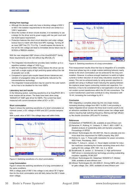
Long Commutation<br />
Figure 5 shows the switching waveforms of a long commutation at<br />
the same conditions.<br />
With a voltage peak of 580 V this voltage is only about 30 V higher<br />
than for the short commutation and still fairly below the 650 V breakdown<br />
voltage.<br />
Figure 5: Switching waveforms of a long commutation<br />
First measurement results show that due to integration of a complete<br />
three-level phase leg into a single module switching behavior nearly<br />
similar to the short commutation can be achieved for the long commutation.<br />
However, to achieve enough headroom to switch at higher<br />
currents a further reduction of circuit stray inductance would be necessary.<br />
This can be achieved easily by using several capacitors in<br />
parallel and using a multilayer board reducing the spacing between<br />
the coplanar power layers connecting module and capacitors. Furthermore,<br />
it has to be considered that a real application circuit would<br />
not contain current transformers within the DC-link connections. The<br />
current transformers used here contribute to stray inductance with<br />
15 nH, increasing the overvoltage by 45 V.<br />
Conclusion<br />
With integrating a complete phase leg into one single module,<br />
increasing blocking voltage from 600 V to 650 V and providing a<br />
highly integrated driver solution the three level inverter proofs to be<br />
an attractive candidate for low and medium power low voltage applications<br />
requiring high switching frequency, filtering and high efficiency<br />
like double conversion UPS and PV inverters.<br />
References<br />
[1] Datasheet of FS6R06VE3_B2, available at www.infineon.com<br />
[2] Kanschat, P.; Rüthing, H.; Umbach, F.; Hille F.: 600 V IGBT³: A<br />
detalied analysis of outstanding static and dynamic properties,<br />
Proceedings of ISPSD<br />
[3] Infineon Technologies AG: AN 2007-04, How to calculate and minimize<br />
dead time requirement for IGBTs properly, May 2007<br />
[4] Holmes G.; Lipo, T.: Pulse width modulation for power converters,<br />
IEEE Press, Piscataway, 2003<br />
[5] Kalker, T.; Ackva A.; Jansen, U.: Novel digital controller for induction<br />
machines considering the inverter swicthing times and a fluctuating<br />
DC-link voltage, EPE 1991, Vol. 2, p. 58-62<br />
[6] Strzalkowski, B; Jansen, U.; Schwarzer, U: High performance<br />
IGBT-driver in microtransformer technology providing outstanding<br />
insulation capability, PCIM 2007<br />
[7] Infineon Technologies AG: Datasheet 1ED020I12-F, Oktober<br />
2008, available at www.infineon.com<br />
[8] Infineon Technologies AG: AN 2006-01, Driving IGBTs with unipolar<br />
gate voltage, Dec. 2005, available at www.infineon.com<br />
www.infineon.com/highpower<br />
30 Bodo´s <strong>Power</strong> Systems ® August 2009 www.bodospower.com