Features - Bodo's Power
Features - Bodo's Power
Features - Bodo's Power
You also want an ePaper? Increase the reach of your titles
YUMPU automatically turns print PDFs into web optimized ePapers that Google loves.
DIGITAL POWER<br />
Control Law Accelerator Boosts<br />
Digital <strong>Power</strong> Performance<br />
Platform of cost sensitive, high performance switching regulators<br />
While adoption of digital control techniques for switched power supplies may never be<br />
universal, interest has been steadily growing in the subject and commercial digital microcontrollers<br />
are now beginning to appear with features optimised for power supply control.<br />
This short article describes a new feature which significantly reduces control loop latency<br />
and extends the performance of the digital controller in power supply applications.<br />
Richard Poley, Field Applications Engineer, Texas Instruments<br />
In digitally controlled switched mode regulators, the control law is<br />
normally required to execute at the switching frequency. For example,<br />
a buck regulator switching at 200kHz would require a digital controller<br />
to sample and convert an output voltage, compute a digital<br />
control law, and deliver an updated PWM duty cycle every 5ìs. This<br />
imposes a limit on the amount of time available for the controller to<br />
process each incoming analogue sample. As switching frequencies<br />
increase, the available processing time for each sample becomes<br />
smaller and the performance of the digital controller becomes more<br />
critical.<br />
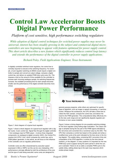
Figure 1: block diagram of a typical buck regulator<br />
Figure 1 shows a block diagram of a typical buck regulator with a digital<br />
3-pole, 3-zero control law. Signal flow through the digital controller<br />
– from analogue input to PWM output – involves three integrated<br />
components: an analogue-to-digital converter (ADC), the Central Processing<br />
Unit (CPU) “core” which computes the control law, and a<br />
PWM pattern generator. In this article, we will focus on the influence<br />
of the controller core on regulator performance.<br />
Controller cores are often characterised by execution speed<br />
expressed in MHz or MIPS, but this can be very misleading. CPU<br />
performance is strongly affected by both the architecture of the core<br />
and the type of code being executed: some cores are designed for<br />
general purpose programs, while others are optimised for specific<br />
types of algorithm, such as image or speech processing, or real-time<br />
control. Whatever the architecture, the CPU will take a finite time to<br />
collect the ADC sample, compute the control law, and deliver the<br />
result to the PWM generator. This computational delay effectively limits<br />
the duty cycle range and can significantly degrade regulator performance<br />
or even cause instability.<br />
Figure 2 shows a timing diagram for one possible switching strategy<br />
for the buck regulator using trailing edge modulation. The output voltage<br />
is sampled during the low part of the PWM signal (indicated by<br />
the red arrow) and converted into a numerical value by the ADC. The<br />
CPU then computes a control law based on this sample and writes a<br />
modified duty cycle at the point indicated by the blue arrow in the timing<br />
diagram. The update delay, comprising ADC conversion time and<br />
computation of the 3P3Z algorithm, is shown by the time interval<br />
marked t d in the diagram. In many systems it is important for the new<br />
PWM duty cycle to appear during the same period in which the output<br />
is sampled. Failure to do so adds a complete PWM cycle to the<br />
update delay, adding phase lag to the open loop response which<br />
erodes phase margin.<br />
32 Bodo´s <strong>Power</strong> Systems ® August 2009 www.bodospower.com


