Features - Bodo's Power
Features - Bodo's Power
Features - Bodo's Power

Create successful ePaper yourself
Turn your PDF publications into a flip-book with our unique Google optimized e-Paper software.
following bulky capacitor. The distorted waveform can be overcome if<br />
a PFC input stage is used. If we apply a Fourier analysis to this signal<br />
we would see a lot of harmonic components.<br />
For example the harmonic content related to the fundamental wave is<br />
20%, the apparent power is calculated as follows:<br />
P<br />
VA<br />
= PW<br />
+ PVAR<br />
P W = Active <strong>Power</strong> [W]<br />
P VA = Apparent <strong>Power</strong> [VA]<br />
P VAR = Reactive <strong>Power</strong> [VAR]<br />
1<br />
0.<br />
2<br />
This results in a 2% lower efficiency of the generator. These extra<br />
losses are produced from the higher current in the copper of the generator.<br />
Beside the copper losses there are also iron losses which are<br />
affected by higher order harmonics.<br />
To control the PMSG normally sinusoidal commutation or field oriented<br />
control is used. The former has limited gain and frequency<br />
response. The time-variant perturbations to the current control loop<br />
cause phase lag in the motor current. This results in less torque off<br />
the generator. Therefore more current is required to maintain the<br />
Figure 5: <strong>Power</strong> stage<br />
Figure 6: Controller part<br />
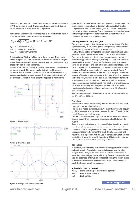
Figure 7: Voltage and current waveform<br />
=<br />
2<br />
+<br />
2<br />
= 1.<br />
019<br />
RENEWABLE ENERGY<br />
same torque. To solve this problem filed oriented control is used. The<br />
current space vector is fixed in direction with respect to the rotor,<br />
independent of rotation. The resulting flux is controlled for optimal<br />
torque with minimal phase lag. Due to this reason, more active power<br />
and less apparent power is transferred from the generator to the<br />
inverter which leads to a higher efficiency.<br />
Feeding power into the public grid<br />
The next step is now to feed the power into the public grid. For the<br />
highest efficiency of the whole system the operating principle of the<br />
line inverter should be understand and optimized.<br />
To show the operating principle the simulation model in figure 5 and<br />
6 is used. The controller part is based on sinusoidal commutation.<br />
The inverter topology is a single phase voltage source inverter.<br />
To feed energy into the public grid, normally a DC-AC converter with<br />
buck capability is used. The current feed to the public grid should<br />
have, for low emission and high efficiency, a sinusoidal shape. With<br />
the appropriate control algorithm it is possible to minimize the reactive<br />
power. Nearly a power factor of -1 can be obtained. Figure 7<br />
shows the simulated wave form feed into the public grid. The disadvantage<br />
of the above buck converter is the need of the line inductors<br />
and some bulky capacitors. The size of the inductors is determined<br />
by the switching frequency of the power stage and the operation<br />
mode (continuous or discontinuous). The result of a lower inductance<br />
value (same switching frequency) is a smaller size. But a lower<br />
inductance value leads to a higher ripple current which affects the<br />
EMC behaviour.<br />
All these aspects should be considered during the design phase to<br />
get an optimised solution.<br />
The future<br />
As mentioned above when working with the back to back converter<br />
there are two main disadvantages.<br />
The line side needs power inductors. Normally the switching frequency<br />
of line inverters is in the range between 5-20 kHz. Therefore, the<br />
buck inductors are relatively large.<br />
The BBC needs electrolytic capacitors on the DC side. The capacitors<br />
are large in their volume and are reducing the life time of the<br />
inverter.<br />
To reduce cost and volume and increase lifetime it could be considered<br />
to develop a generator inverter combination. Therefore, the<br />
inverter is a part of the generator housing. This is only possible with<br />
a very compact inverter without the need of bulky capacitors and<br />
inductors. This is possible with the use of a matrix converter. We calculated<br />
that it would be possible to design a 20kW matrix converter<br />
with a volume of only 3.3dm3 (including EMI Filter).<br />
Conclusion<br />
In summary, understanding of the different parts (generator, inverter<br />
and control part) of small wind power stations can lead to better<br />
designs. Better designs are more reliable and the most important<br />
point, they have a higher overall efficiency. Several points and strategies<br />
are described and must be considered during the design phase<br />
of inverters for small wind power stations in the kilo watt range to<br />
reach the highest overall performance.<br />
Abbreviation used in the text<br />
PMSG Permanent magnet synchronous generator<br />
BBC Back to Back converter<br />
LUT Look up table<br />
www.negal.ch<br />
www.bodospower.com August 2009 Bodo´s <strong>Power</strong> Systems ®<br />
www.bodospower.com August 2009 Bodo´s <strong>Power</strong> Systems ®<br />
www.bodospower.com August 2009 Bodo´s <strong>Power</strong> Systems ®<br />
35