Ed. 07/2006 - Scotsman
Ed. 07/2006 - Scotsman
Ed. 07/2006 - Scotsman

You also want an ePaper? Increase the reach of your titles
YUMPU automatically turns print PDFs into web optimized ePapers that Google loves.
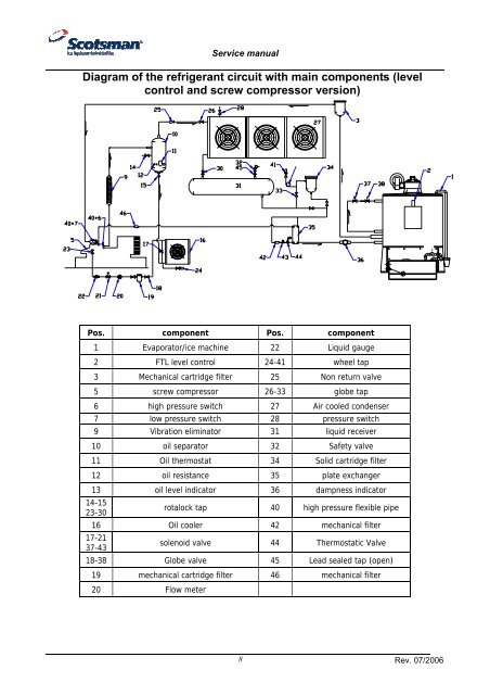
Service manual<br />
Diagram of the refrigerant circuit with main components (level<br />
control and screw compressor version)<br />
Pos. component Pos. component<br />
1 Evaporator/ice machine 22 Liquid gauge<br />
2 FTL level control 24-41 wheel tap<br />
3 Mechanical cartridge filter 25 Non return valve<br />
5 screw compressor 26-33 globe tap<br />
6 high pressure switch 27 Air cooled condenser<br />
7 low pressure switch 28 pressure switch<br />
9 Vibration eliminator 31 liquid receiver<br />
10 oil separator 32 Safety valve<br />
11 Oil thermostat 34 Solid cartridge filter<br />
12 oil resistance 35 plate exchanger<br />
13 oil level indicator 36 dampness indicator<br />
14-15<br />
23-30<br />
rotalock tap 40 high pressure flexible pipe<br />
16 Oil cooler 42 mechanical filter<br />
17-21<br />
37-43<br />
solenoid valve 44 Thermostatic Valve<br />
18-38 Globe valve 45 Lead sealed tap (open)<br />
19 mechanical cartridge filter 46 mechanical filter<br />
20 Flow meter<br />
8<br />
Rev. <strong>07</strong>/<strong>2006</strong>