EEN1016 Electronics I - Faculty of Engineering - Multimedia University
EEN1016 Electronics I - Faculty of Engineering - Multimedia University
EEN1016 Electronics I - Faculty of Engineering - Multimedia University

You also want an ePaper? Increase the reach of your titles
YUMPU automatically turns print PDFs into web optimized ePapers that Google loves.
<strong>EEN1016</strong> <strong>Electronics</strong> I: Appendices<br />
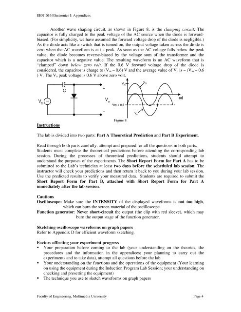
Another wave shaping circuit, as shown in Figure 8, is the clamping circuit. The<br />
capacitor is fully charged to the peak voltage <strong>of</strong> the AC source when the diode is forwardbiased.<br />
(For simplicity, we have assumed the forward voltage drop <strong>of</strong> the diode is negligible.)<br />
As the diode acts like a switch that is turned on, the output voltage taken across the diode is<br />
zero when the AC waveform is at its peak. As soon as the AC voltage falls below the peak<br />
value, the diode becomes reverse-biased by the voltage sum <strong>of</strong> the transformer and the<br />
capacitor which is a negative value. The resulting waveform is an AC waveform that is<br />
“clamped” down below zero volt. If the 0.6 V forward voltage drop <strong>of</strong> the diode is<br />
considered, the capacitor is charge to (V m – 0.6) V and the average value <strong>of</strong> V o is – (V m – 0.6<br />
) V. The V o peak voltage is 0.6 V above zero volt.<br />
C<br />
+<br />
V m<br />
V S<br />
V S<br />
~<br />
V o<br />
-Vm + 0.6<br />
ωt<br />
-<br />
V o<br />
Instructions<br />
Figure 8<br />
The lab is divided into two parts: Part A Theoretical Prediction and Part B Experiment.<br />
Read through both parts carefully, attempt and prepared for all the questions in both parts.<br />
Students must complete the theoretical predictions before attending the corresponding lab<br />
session. During the processes <strong>of</strong> theoretical predictions, students should attempt to<br />
understand the purposes <strong>of</strong> the experiments. The Short Report Form for Part A has to be<br />
submitted to the Lab’s technician at least two days before the scheduled lab session. The<br />
instructor will check your predictions and then return it back to you during your lab session.<br />
Use the predicted results to verify your measured data. Students are required to submit the<br />
Short Report Form for Part B, attached with Short Report Form for Part A<br />
immediately after the lab session.<br />
Cautions<br />
Oscilloscope: Make sure the INTENSITY <strong>of</strong> the displayed waveforms is not too high,<br />
which can burn the screen material <strong>of</strong> the oscilloscope.<br />
Function generator: Never short-circuit the output (the clip with red sleeve), which may<br />
burn the output stage <strong>of</strong> the function generator.<br />
Sketching oscilloscope waveforms on graph papers<br />
Refer to Appendix D for efficient waveform sketching.<br />
Factors affecting your experiment progress<br />
Your preparation before coming to the lab (your understanding on the theories, the<br />
procedures and the information in the appendices; your planning to carry out the<br />
experiments and to take data), attempt all questions before the lab.<br />
Your understanding on the functions and the operations <strong>of</strong> the equipment (Your learning<br />
on using the equipment during the Induction Program Lab Session; your understanding on<br />
checking and presetting the equipment)<br />
The technique you use to sketch waveforms on graph papers<br />
<strong>Faculty</strong> <strong>of</strong> <strong>Engineering</strong>, <strong>Multimedia</strong> <strong>University</strong> Page 4