The Direct Wave Form Digital Filter Structure - Signal Processing ...
The Direct Wave Form Digital Filter Structure - Signal Processing ...
The Direct Wave Form Digital Filter Structure - Signal Processing ...
Create successful ePaper yourself
Turn your PDF publications into a flip-book with our unique Google optimized e-Paper software.
And finally, more so than the <strong>Wave</strong> <strong>Digital</strong> <strong>Form</strong> in [1],<br />
the DWF is a universal ‘biquad’, i.e. an IIR second-order<br />
section to create the standard filter types in a generic way.<br />
For example, taking η 1 = η 2 = 0 creates a bandpass filter<br />
(zeros at ±1), while high- and lowpass filters result from<br />
either η 1 = 0, or η 2 = 0. Next, if we take d = − 1 2<br />
(1+b) in<br />
the bandpass solution and add x[n] to the output, a bandstop<br />
filter is created with transfer function<br />
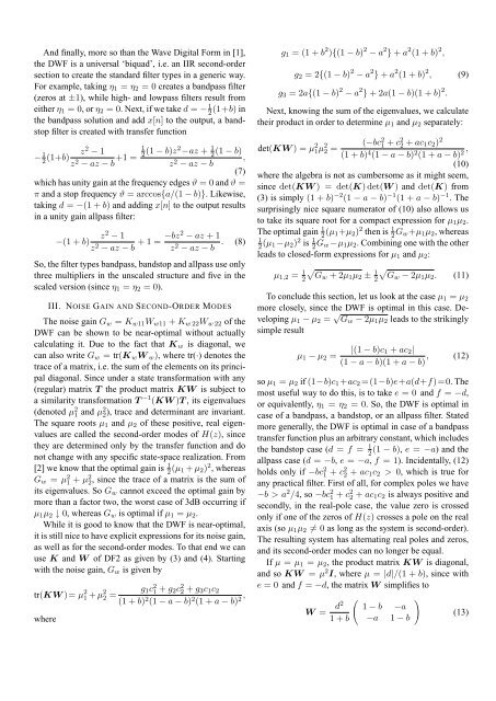
− 1 2 (1+b) z 2 1<br />
− 1<br />
z 2 − az − b +1 = 2 (1 − b)z2 −az + 1 2<br />
(1 − b)<br />
z 2 ,<br />
− az − b<br />
(7)<br />
which has unity gain at the frequency edges ϑ = 0 and ϑ =<br />
π and a stop frequency ϑ = arccos{a/(1 − b)}. Likewise,<br />
taking d = −(1 + b) and adding x[n] to the output results<br />
in a unity gain allpass filter:<br />
z 2 − 1<br />
−(1 + b)<br />
z 2 − az − b + 1 = −bz2 − az + 1<br />
z 2 − az − b . (8)<br />
So, the filter types bandpass, bandstop and allpass use only<br />
three multipliers in the unscaled structure and five in the<br />
scaled version (since η 1 = η 2 = 0).<br />
III. NOISE GAIN AND SECOND-ORDER MODES<br />
<strong>The</strong> noise gain G w = K w11 W w11 + K w 22 W w 22 of the<br />
DWF can be shown to be near-optimal without actually<br />
calculating it. Due to the fact that K w is diagonal, we<br />
can also write G w = tr(K w W w ), where tr(·) denotes the<br />
trace of a matrix, i.e. the sum of the elements on its principal<br />
diagonal. Since under a state transformation with any<br />
(regular) matrix T the product matrix KW is subject to<br />
a similarity transformation T −1 (KW )T , its eigenvalues<br />
(denoted µ 2 1 and µ2 2 ), trace and determinant are invariant.<br />
<strong>The</strong> square roots µ 1 and µ 2 of these positive, real eigenvalues<br />
are called the second-order modes of H(z), since<br />
they are determined only by the transfer function and do<br />
not change with any specific state-space realization. From<br />
[2] we know that the optimal gain is 1 2 (µ 1 + µ 2 ) 2 , whereas<br />
G w = µ 2 1 + µ2 2 , since the trace of a matrix is the sum of<br />
its eigenvalues. So G w cannot exceed the optimal gain by<br />
more than a factor two, the worst case of 3dB occurring if<br />
µ 1 µ 2 ↓ 0, whereas G w is optimal if µ 1 = µ 2 .<br />
While it is good to know that the DWF is near-optimal,<br />
it is still nice to have explicit expressions for its noise gain,<br />
as well as for the second-order modes. To that end we can<br />
use K and W of DF2 as given by (3) and (4). Starting<br />
with the noise gain, G w is given by<br />
tr(KW )= µ 2 1 + µ 2 g 1 c 2 1<br />
2 =<br />
+ g 2c 2 2 + g 3c 1 c 2<br />
(1 + b) 2 (1 − a − b) 2 (1 + a − b) 2 ,<br />
where<br />
g 1 = (1 + b 2 ){(1 − b) 2 − a 2 } + a 2 (1 + b) 2 ,<br />
g 2 = 2{(1 − b) 2 − a 2 } + a 2 (1 + b) 2 , (9)<br />
g 3 = 2a{(1 − b) 2 − a 2 } + 2a(1 − b)(1 + b) 2 .<br />
Next, knowing the sum of the eigenvalues, we calculate<br />
their product in order to determine µ 1 and µ 2 separately:<br />
det(KW ) = µ 2 1µ 2 (−bc 2 1<br />
2 =<br />
+ c2 2 + ac 1c 2 ) 2<br />
(1 + b) 4 (1 − a − b) 2 (1 + a − b) 2 ,<br />
(10)<br />
where the algebra is not as cumbersome as it might seem,<br />
since det(KW ) = det(K) det(W ) and det(K) from<br />
(3) is simply (1 + b) −2 (1 − a − b) −1 (1 + a − b) −1 . <strong>The</strong><br />
surprisingly nice square numerator of (10) also allows us<br />
to take its square root for a compact expression for µ 1 µ 2 .<br />
<strong>The</strong> optimal gain 1 2 (µ 1+µ 2 ) 2 then is 1 2 G w+µ 1 µ 2 , whereas<br />
1<br />
2 (µ 1 −µ 2 ) 2 is 1 2 G w −µ 1 µ 2 . Combining one with the other<br />
leads to closed-form expressions for µ 1 and µ 2 :<br />
µ 1,2 = 1 2√<br />
Gw + 2µ 1 µ 2 ± 1 2√<br />
Gw − 2µ 1 µ 2 . (11)<br />
To conclude this section, let us look at the case µ 1 = µ 2<br />
more closely, since the DWF is optimal in this case. Developing<br />
µ 1 − µ 2 = √ G w − 2µ 1 µ 2 leads to the strikingly<br />
simple result<br />
µ 1 − µ 2 =<br />
|(1 − b)c 1 + ac 2 |<br />
(1 − a − b)(1 + a − b) , (12)<br />
so µ 1 = µ 2 if (1−b)c 1 +ac 2 =(1−b)e+a(d+f)=0. <strong>The</strong><br />
most useful way to do this, is to take e = 0 and f = −d,<br />
or equivalently, η 1 = η 2 = 0. So, the DWF is optimal in<br />
case of a bandpass, a bandstop, or an allpass filter. Stated<br />
more generally, the DWF is optimal in case of a bandpass<br />
transfer function plus an arbitrary constant, which includes<br />
the bandstop case (d = f = 1 2<br />
(1 − b), e = −a) and the<br />
allpass case (d = −b, e = −a, f = 1). Incidentally, (12)<br />
holds only if −bc 2 1 + c2 2 + ac 1c 2 > 0, which is true for<br />
any practical filter. First of all, for complex poles we have<br />
−b > a 2 /4, so −bc 2 1 + c2 2 + ac 1c 2 is always positive and<br />
secondly, in the real-pole case, the value zero is crossed<br />
only if one of the zeros of H(z) crosses a pole on the real<br />
axis (so µ 1 µ 2 ≠ 0 as long as the system is second-order).<br />
<strong>The</strong> resulting system has alternating real poles and zeros,<br />
and its second-order modes can no longer be equal.<br />
If µ = µ 1 = µ 2 , the product matrix KW is diagonal,<br />
and so KW = µ 2 I, where µ = |d|/(1 + b), since with<br />
e = 0 and f = −d, the matrix W simplifies to<br />
W =<br />
d2<br />
(<br />
1 − b −a<br />
1 + b −a 1 − b<br />
)<br />
(13)


