

Variable Angle-of-Attack Profile Entry Guidance for a Crewed Lifting ...
Variable Angle-of-Attack Profile Entry Guidance for a Crewed Lifting ...
Variable Angle-of-Attack Profile Entry Guidance for a Crewed Lifting ...

You also want an ePaper? Increase the reach of your titles
YUMPU automatically turns print PDFs into web optimized ePapers that Google loves.
IV.<br />
Results and Discussion<br />
A. Nominal and Stress Case Per<strong>for</strong>mance<br />
Nominal entry trajectory per<strong>for</strong>mance at undeflected-LBF trim α <strong>for</strong> ascending and descending approaches<br />
to KSC is shown in Fig. 8 and Table 4. Figure 8(b) shows only a small l<strong>of</strong>t is required to limit the peak<br />
heat rate and provide the required downrange to reach the target. Figure 8(d) shows small flight-path angles<br />
are maintained through the bulk <strong>of</strong> the hypersonic phase, illustrating the long, low-deceleration equilibrium<br />
glide possible with a lifting body. All constraints are satisfied <strong>for</strong> both approaches. The primary difference<br />
between the trajectories is a more flattened g-pulse exhibited by the descending approach, caused by the<br />
longer entry range associated with this trajectory.<br />
The bank command and response histories <strong>for</strong> the ascending and descending approaches are shown<br />
in Fig. 9(a) and (b), respectively. The histories are similar: the initial bank command <strong>of</strong> 0 deg quickly<br />
transitions to a near lift-neutral command <strong>of</strong> approximately 75 deg during the energy depletion phase. The<br />
guidance transition to range targeting is easily seen near 24,000 ft/s where the bank command magnitude<br />
becomes relatively constant near 50 deg as the guidance algorithm solves the constant bank range problem.<br />
The ascending approach per<strong>for</strong>ms 6 bank reversals; the descending per<strong>for</strong>ms 5. This compares well to STS,<br />
which typically per<strong>for</strong>ms 4 reversals. 22 Immediately prior to TAEM initiation, the vehicle banks to a near<br />
lift-up orientation while maintaining a small amount <strong>of</strong> heading control. This pull-up maneuver unloads the<br />
vehicle (see Fig. 8(c)) and provides a clean transition to the TAEM phase.<br />
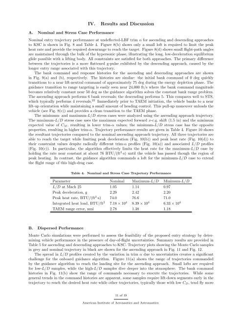
The minimum- and maximum-L/D stress cases were analyzed using the ascending approach trajectory.<br />
The maximum-L/D stress case uses the maximum expected <strong>for</strong>ward x-c.g. shift (1.5 in) and the minimum<br />
expected value <strong>of</strong> C M , resulting in lower trim-α values; the minimum-L/D stress case has the opposite<br />
properties, resulting in higher trim-α. Trajectory per<strong>for</strong>mance results are given in Table 4. Figure 10 shows<br />
the resultant trajectories compared to the nominal ascending approach trajectory. All three trajectories are<br />
able to reach the target while limiting peak deceleration (Fig. 10(b)) and peak heat rate (Fig. 10(d)) to<br />
their constraint values despite radically different trim-α pr<strong>of</strong>iles (Fig. 10(a)) and associated L/D pr<strong>of</strong>iles<br />
(Fig. 10(c)). In particular, the algorithm effectively limits the heat rate <strong>for</strong> the maximum-L/D case by<br />
holding the rate near constant at about 76 BTU/(ft 2·s) until the vehicle has passed though the region <strong>of</strong><br />
peak heating. In contrast, the guidance algorithm commands a l<strong>of</strong>t <strong>for</strong> the minimum-L/D case to extend<br />
the flight range <strong>of</strong> this high-drag case.<br />
Table 4.<br />
Nominal and Stress Case Trajectory Per<strong>for</strong>mance<br />
Parameter Nominal Maximum-L/D Minimum-L/D<br />
L/D at Mach 25 1.05 1.14 0.97<br />
Peak deceleration, g 2.29 2.42 2.20<br />
Peak heat rate, BTU/(ft 2·s) 74.0 76.6 71.0<br />
Integrated heat load, BTU/ft 2 7.18 × 10 4 8.39 × 10 4 6.33 × 10 4<br />
TAEM range error, nmi 2.78 1.38 1.18<br />
B. Dispersed Per<strong>for</strong>mance<br />
Monte Carlo simulations were per<strong>for</strong>med to assess the feasibility <strong>of</strong> the proposed entry strategy by determining<br />
vehicle per<strong>for</strong>mance in the presence <strong>of</strong> day-<strong>of</strong>-flight uncertainties. Summary results are provided in<br />
Table 5 <strong>for</strong> ascending and descending approaches to KSC. Trajectory plots showing the Monte Carlo samples<br />
in grey and nominal trajectory in black are shown <strong>for</strong> the ascending approach in Fig. 11 and Fig. 12.<br />
The spread in L/D pr<strong>of</strong>iles created by the variation in trim α due to uncertainties creates a significant<br />
challenge <strong>for</strong> the onboard guidance algorithm. Figure 11(a) shows the range <strong>of</strong> trajectories commanded<br />
by the guidance algorithm to reach the landing site <strong>for</strong> the ascending approach. Small l<strong>of</strong>ts are required<br />
<strong>for</strong> low-L/D samples, while the high-L/D samples dive deeper into the atmosphere. The bank command<br />
histories in Fig. 11(b) show the range <strong>of</strong> commands necessary to execute the trajectories. While some<br />
general trends in the command histories are apparent, some samples require lift-down segments early in the<br />
trajectory to reach the desired heat rate while other trajectories, typically those with low C D , tend fly more<br />
11 <strong>of</strong> 19<br />
American Institute <strong>of</strong> Aeronautics and Astronautics


