

Variable Angle-of-Attack Profile Entry Guidance for a Crewed Lifting ...
Variable Angle-of-Attack Profile Entry Guidance for a Crewed Lifting ...
Variable Angle-of-Attack Profile Entry Guidance for a Crewed Lifting ...

You also want an ePaper? Increase the reach of your titles
YUMPU automatically turns print PDFs into web optimized ePapers that Google loves.
command to less than 45 deg while continuing to execute the downrange targeting logic. This ensures that<br />
the majority <strong>of</strong> the lift is in the vertical direction, while reserving enough lateral control authority to enable<br />
the vehicle to point its velocity vector towards the target. Due to the short amount <strong>of</strong> remaining time<br />
be<strong>for</strong>e TAEM initiation, the vehicle does not have the capability to substantially influence the downrange<br />
flown during this phase. The guidance algorithm terminates at the end <strong>of</strong> heading alignment at 2,500 ft/s<br />
Earth-relative velocity, and control is notionally handed <strong>of</strong>f to a TAEM algorithm.<br />
C. Lateral <strong>Guidance</strong><br />
Since the vehicle is flying at undeflected trim α and the vertical lift magnitude is controlled by the longitudinal<br />
channel, the only control parameter available <strong>for</strong> lateral (crossrange) control is the sign <strong>of</strong> the out-<strong>of</strong>-plane<br />
component <strong>of</strong> the lift. This is controlled through bank reversals. Crossrange is managed by limiting the<br />
azimuth error. The maximum allowable azimuth error defines a corridor that decreases with velocity; this<br />
ensures that the crossrange error decreases as vehicle range control authority decreases during entry. A<br />
bank reversal is triggered when the azimuth error exceeds the corridor boundary. The initial azimuth error<br />
corridor width is decreased to <strong>for</strong>ce an early bank reversal <strong>for</strong> high-L/D cases. Bank reversals are per<strong>for</strong>med<br />
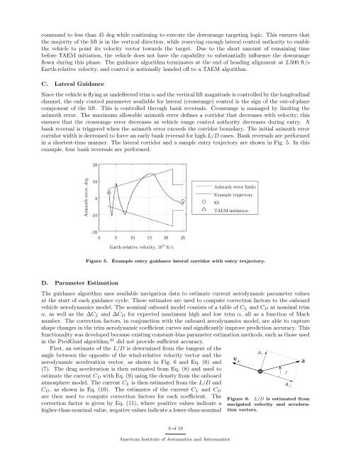
in a shortest-time manner. The lateral corridor and a sample entry trajectory are shown in Fig. 5. In this<br />
example, four bank reversals are per<strong>for</strong>med.<br />
Figure 5.<br />
Example entry guidance lateral corridor with entry trajectory.<br />
D. Parameter Estimation<br />
The guidance algorithm uses available navigation data to estimate current aerodynamic parameter values<br />
at the start <strong>of</strong> each guidance cycle. These estimates are used to compute correction factors to the onboard<br />
vehicle aerodynamics model. The nominal onboard model consists <strong>of</strong> a table <strong>of</strong> C L and C D at nominal trim<br />
α, as well as the ∆C L and ∆C D <strong>for</strong> expected maximum high and low trim α, all as a function <strong>of</strong> Mach<br />
number. The correction factors, in conjunction with the onboard aerodynamics model, are able to capture<br />
shape changes in the trim aerodynamic coefficient curves and significantly improve prediction accuracy. This<br />
functionality was developed because existing constant-bias parameter estimation methods, such as those used<br />
in the PredGuid algorithm, 21 did not provide sufficient accuracy.<br />
First, an estimate <strong>of</strong> the L/D is determined from the tangent <strong>of</strong> the<br />
angle between the opposite <strong>of</strong> the wind-relative velocity vector and the<br />
aerodynamic acceleration vector, as shown in Fig. 6 and Eq. (6) and<br />
(7). The drag acceleration is then estimated from Eq. (8) and used to<br />
estimate the current C D with Eq. (9) using the density from the onboard<br />
atmosphere model. The current C L is then estimated from the L/D and<br />
C D , as shown in Eq. (10). The estimates <strong>of</strong> the current C L and C D<br />
are then used to compute correction factors <strong>for</strong> each coefficient. The<br />
correction factor is given by Eq. (11), where positive values indicate a<br />
higher-than-nominal value, negative values indicate a lower-than-nominal<br />
Figure 6. L/D is estimated from<br />
navigated velocity and acceleration<br />
vectors.<br />
9 <strong>of</strong> 19<br />
American Institute <strong>of</strong> Aeronautics and Astronautics


