

Variable Angle-of-Attack Profile Entry Guidance for a Crewed Lifting ...
Variable Angle-of-Attack Profile Entry Guidance for a Crewed Lifting ...
Variable Angle-of-Attack Profile Entry Guidance for a Crewed Lifting ...

You also want an ePaper? Increase the reach of your titles
YUMPU automatically turns print PDFs into web optimized ePapers that Google loves.
Subscript<br />
cmd Command nom Nominal<br />
est Estimate rel Earth-relative frame<br />
i Index w Wind-relative frame<br />
I. Introduction<br />
<strong>Lifting</strong> body entry vehicles provide several advantages over blunt body capsules <strong>for</strong> human return from<br />
low-Earth orbit (LEO), where mission design flexibility and minimizing crew recovery time are important<br />
operational goals. Relative to capsules, lifting bodies possess high hypersonic lift-to-drag ratios which enable<br />
low peak deceleration entries and provide significant crossrange capability. This crossrange capability directly<br />
improves landing opportunity frequency from LEO. <strong>Lifting</strong> bodies may also per<strong>for</strong>m runway landings,<br />
simplifying recovery and eliminating the need <strong>for</strong> parachutes or terminal deceleration systems.<br />
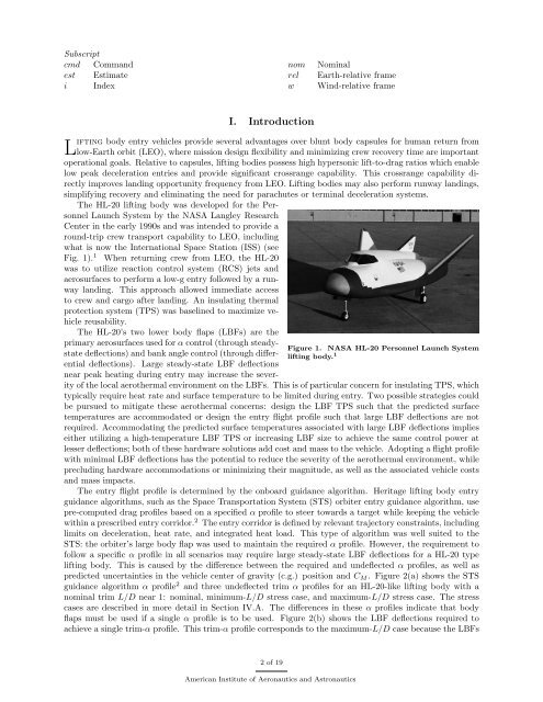
The HL-20 lifting body was developed <strong>for</strong> the Personnel<br />
Launch System by the NASA Langley Research<br />
Center in the early 1990s and was intended to provide a<br />
round-trip crew transport capability to LEO, including<br />
what is now the International Space Station (ISS) (see<br />
Fig. 1). 1 When returning crew from LEO, the HL-20<br />
was to utilize reaction control system (RCS) jets and<br />
aerosurfaces to per<strong>for</strong>m a low-g entry followed by a runway<br />
landing. This approach allowed immediate access<br />
to crew and cargo after landing. An insulating thermal<br />
protection system (TPS) was baselined to maximize vehicle<br />
reusability.<br />
The HL-20’s two lower body flaps (LBFs) are the<br />
primary aerosurfaces used <strong>for</strong> α control (through steadystate<br />
deflections) and bank angle control (through differ-<br />
lifting body. 1<br />
Figure 1. NASA HL-20 Personnel Launch System<br />
ential deflections). Large steady-state LBF deflections<br />
near peak heating during entry may increase the severity<br />
<strong>of</strong> the local aerothermal environment on the LBFs. This is <strong>of</strong> particular concern <strong>for</strong> insulating TPS, which<br />
typically require heat rate and surface temperature to be limited during entry. Two possible strategies could<br />
be pursued to mitigate these aerothermal concerns: design the LBF TPS such that the predicted surface<br />
temperatures are accommodated or design the entry flight pr<strong>of</strong>ile such that large LBF deflections are not<br />
required. Accommodating the predicted surface temperatures associated with large LBF deflections implies<br />
either utilizing a high-temperature LBF TPS or increasing LBF size to achieve the same control power at<br />
lesser deflections; both <strong>of</strong> these hardware solutions add cost and mass to the vehicle. Adopting a flight pr<strong>of</strong>ile<br />
with minimal LBF deflections has the potential to reduce the severity <strong>of</strong> the aerothermal environment, while<br />
precluding hardware accommodations or minimizing their magnitude, as well as the associated vehicle costs<br />
and mass impacts.<br />
The entry flight pr<strong>of</strong>ile is determined by the onboard guidance algorithm. Heritage lifting body entry<br />
guidance algorithms, such as the Space Transportation System (STS) orbiter entry guidance algorithm, use<br />
pre-computed drag pr<strong>of</strong>iles based on a specified α pr<strong>of</strong>ile to steer towards a target while keeping the vehicle<br />
within a prescribed entry corridor. 2 The entry corridor is defined by relevant trajectory constraints, including<br />
limits on deceleration, heat rate, and integrated heat load. This type <strong>of</strong> algorithm was well suited to the<br />
STS: the orbiter’s large body flap was used to maintain the required α pr<strong>of</strong>ile. However, the requirement to<br />
follow a specific α pr<strong>of</strong>ile in all scenarios may require large steady-state LBF deflections <strong>for</strong> a HL-20 type<br />
lifting body. This is caused by the difference between the required and undeflected α pr<strong>of</strong>iles, as well as<br />
predicted uncertainties in the vehicle center <strong>of</strong> gravity (c.g.) position and C M . Figure 2(a) shows the STS<br />
guidance algorithm α pr<strong>of</strong>ile 2 and three undeflected trim α pr<strong>of</strong>iles <strong>for</strong> an HL-20-like lifting body with a<br />
nominal trim L/D near 1: nominal, minimum-L/D stress case, and maximum-L/D stress case. The stress<br />
cases are described in more detail in Section IV.A. The differences in these α pr<strong>of</strong>iles indicate that body<br />
flaps must be used if a single α pr<strong>of</strong>ile is to be used. Figure 2(b) shows the LBF deflections required to<br />
achieve a single trim-α pr<strong>of</strong>ile. This trim-α pr<strong>of</strong>ile corresponds to the maximum-L/D case because the LBFs<br />
2 <strong>of</strong> 19<br />
American Institute <strong>of</strong> Aeronautics and Astronautics


