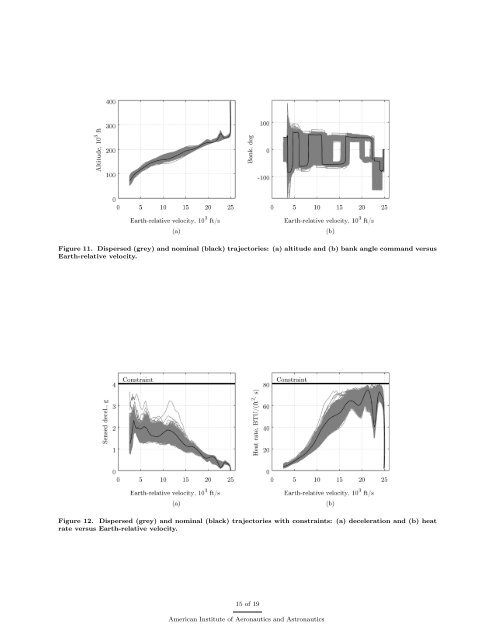
lift down orientations late in the trajectory to avoid overshooting the target. However, as seen in the nominal trajectories in Section A, Fig. 12(a) shows that the algorithm effectively limits the deceleration to below 4 g, with most samples below 2.5 g. The algorithm is also able to limit the peak heat rate: only a single sample violates the 80 BTU/(ft 2·s) limit, and only by a small amount (Fig. 12(b)). Integrated heat loads are also well below the required limit (see Table 5). While the mean plus three-standard-deviation value <strong>of</strong> 4.92 nmi <strong>for</strong> the ascending approach is within the accuracy requirement, the mean plus three-standard-deviation value <strong>for</strong> the descending approach <strong>of</strong> 5.82 nmi exceeds the requirement. The TAEM range error exceeds 5 nmi <strong>for</strong> 4 and 17 samples <strong>for</strong> the ascending and descending approaches, respectively. However, these misses are small, with maximum values <strong>of</strong> 5.63 and 6.75 nmi <strong>for</strong> the ascending and descending approaches, respectively. These misses are not caused by control saturation, but are artifacts <strong>of</strong> the guidance scheme. First, the guidance algorithm does not attempt to null crossrange error. This strategy greatly simplifies the algorithm by allowing the lateral guidance to be fully decoupled from the longitudinal guidance, but it <strong>for</strong>ces the guidance and mission designers to choose between terminal accuracy and excessive bank reversals near the end <strong>of</strong> the trajectory. However, even this choice is limited: additional bank reversals introduce additional excursions from the longitudinal bank command, further degrading accuracy. Second, the algorithm’s numeric predictor uses simplified two-dimensional equations <strong>of</strong> motion over a spherical Earth. While geodetic target coordinates have been converted to their geocentric equivalent <strong>for</strong> the algorithm, the assumptions inherent in using the reducedorder equations <strong>of</strong> motion over a spherical Earth introduce error into the guidance algorithm’s knowledge <strong>of</strong> the target location, even when perfect navigation knowledge is assumed. Lastly, irrespective <strong>of</strong> the accuracy requirement, appropriately designed TAEM and approach and landing algorithms can steer out the errors present at TAEM initiation. Overall, the developed guidance algorithm shows good per<strong>for</strong>mance, indicating that it is feasible to fly a lifting body without steady-state LBF deflections. However, even small steady-state deflections <strong>of</strong> 5 deg may significantly reduce the range <strong>of</strong> trim-α pr<strong>of</strong>iles the guidance algorithm must accommodate, potentially improving per<strong>for</strong>mance and increasing system margin. Table 5. Monte Carlo Results Parameter Ascending approach Descending approach Mean Std. dev. Min. Max. Mean Std. dev. Min. Max. L/D at Mach 25 1.05 0.0382 0.956 1.17 1.05 0.0382 0.956 1.17 Peak deceleration, g 2.33 0.177 1.94 3.62 2.11 0.193 1.60 3.92 Peak heat rate, BTU/(ft 2·s) 74.3 1.78 69.7 80.5 73.1 2.74 65.7 80.3 Heat load, 10 4 BTU/ft 2 7.21 0.417 6.24 8.48 7.28 0.417 6.29 8.63 TAEM range error, nmi 2.25 0.889 0.0838 5.63 2.46 1.12 0.155 6.75 TAEM altitude, 10 3 ft 71.2 0.791 50.9 90.8 72.6 8.08 53.8 92.6 C. Mission Design Flexibility In addition to uncertainty analysis, the robustness <strong>of</strong> undeflected-LBF flight per<strong>for</strong>mance was evaluated through parametric scans related to mission design quantities <strong>of</strong> interest. First, the target latitude and longitude coordinates were varied to evaluate nominal guided range capability. Second, the EI Earth-relative velocity and flight-path angle were varied about the nominal ascending approach EI point to determine the size <strong>of</strong> the entry corridor. The range capability with undeflected LBFs is shown in Fig. 13. The guided range capability is defined to be the locus <strong>of</strong> target locations <strong>for</strong> which the vehicle meets all constraints. In this case, only the accuracy and deceleration constraints are active; the peak heat rate and heat load constraints do not limit the range capability. From the nominal ascending EI point, the downrange capability covers approximately 1900 nmi, with shorter and longer downranges possible <strong>for</strong> landing sites <strong>of</strong>f the centerline <strong>of</strong> the range capability. The maximum crossrange is approximately ±660 nmi. While this crossrange capability is less than STS requirement <strong>of</strong> ±750 nmi, 23 it still provides operational flexibility <strong>for</strong> crew return from LEO and <strong>of</strong>fers significant per<strong>for</strong>mance benefits over capsule-type entry vehicles, which typically have a maximum crossrange 14 <strong>of</strong> 19 American Institute <strong>of</strong> Aeronautics and Astronautics
Figure 11. Dispersed (grey) and nominal (black) trajectories: (a) altitude and (b) bank angle command versus Earth-relative velocity. Figure 12. Dispersed (grey) and nominal (black) trajectories with constraints: (a) deceleration and (b) heat rate versus Earth-relative velocity. 15 <strong>of</strong> 19 American Institute <strong>of</strong> Aeronautics and Astronautics