

Variable Angle-of-Attack Profile Entry Guidance for a Crewed Lifting ...
Variable Angle-of-Attack Profile Entry Guidance for a Crewed Lifting ...
Variable Angle-of-Attack Profile Entry Guidance for a Crewed Lifting ...

Create successful ePaper yourself
Turn your PDF publications into a flip-book with our unique Google optimized e-Paper software.
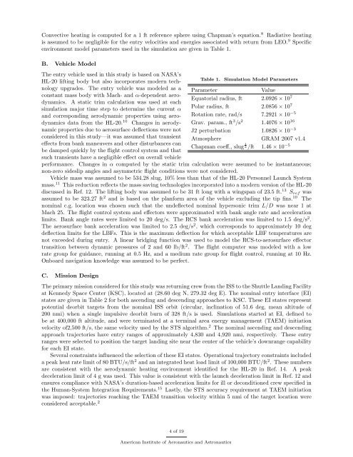
Convective heating is computed <strong>for</strong> a 1 ft reference sphere using Chapman’s equation. 8 Radiative heating<br />
is assumed to be negligible <strong>for</strong> the entry velocities and energies associated with return from LEO. 9 Specific<br />
environment model parameters used in the simulation are given in Table 1.<br />
B. Vehicle Model<br />
The entry vehicle used in this study is based on NASA’s<br />
HL-20 lifting body but also incorporates modern technology<br />
upgrades. The entry vehicle was modeled as a<br />
constant mass body with Mach- and α-dependent aerodynamics.<br />
A static trim calculation was used at each<br />
simulation major time step to determine the current α<br />
and corresponding aerodynamic properties using aerodynamics<br />
data from the HL-20. 10 Changes in aerodynamic<br />
properties due to aerosurface deflections were not<br />
considered in this study—it was assumed that transient<br />
effects from bank maneuvers and other disturbances can<br />
be damped quickly by the flight control system and that<br />
such transients have a negligible effect on overall vehicle<br />
Table 1.<br />
Simulation Model Parameters<br />
Parameter<br />
Value<br />
Equatorial radius, ft 2.0926 × 10 7<br />
Polar radius, ft 2.0856 × 10 7<br />
Rotation rate, rad/s 7.2921 × 10 −5<br />
Grav. param., ft 3 /s 2 1.4076 × 10 16<br />
J2 perturbation<br />
1.0826 × 10 −3<br />
Atmosphere GRAM 2007 v1.4<br />
Chapman coeff., slug 1 2 /ft 1.46 × 10 −5<br />
per<strong>for</strong>mance. Changes in α computed by the static trim calculation were assumed to be instantaneous;<br />
non-zero sideslip angles and asymmetric flight conditions were not considered.<br />
Vehicle mass was assumed to be 534.28 slug, 10% less than that <strong>of</strong> the HL-20 Personnel Launch System<br />
mass. 11 This reduction reflects the mass saving technologies incorporated into a modern version <strong>of</strong> the HL-20<br />
discussed in Ref. 12. The lifting body was assumed to be 31 ft long with a wingspan <strong>of</strong> 23.5 ft. 13 S ref was<br />
assumed to be 323.27 ft 2 and is based on the plan<strong>for</strong>m area <strong>of</strong> the vehicle excluding the tip fins. 10 The<br />
nominal c.g. location was chosen such that the undeflected nominal hypersonic trim L/D was near 1 at<br />
Mach 25. The flight control system and effectors were approximated with bank angle rate and acceleration<br />
limits. Bank angle rates were limited to 20 deg/s. The RCS bank acceleration was limited to 1.5 deg/s 2 .<br />
The aerosurface bank acceleration was limited to 2.5 deg/s 2 , which corresponds to approximately 10 deg<br />
deflection limits <strong>for</strong> the LBFs. This is the maximum deflection <strong>for</strong> which acceptable LBF temperatures are<br />
not exceeded during entry. A linear bridging function was used to model the RCS-to-aerosurface effector<br />
transition between dynamic pressures <strong>of</strong> 2 and 60 lb/ft 2 . The flight computer was modeled with a low<br />
rate group <strong>for</strong> guidance, running at 0.5 Hz, and a medium rate group <strong>for</strong> flight control, running at 10 Hz.<br />
Onboard navigation knowledge was assumed to be perfect.<br />
C. Mission Design<br />
The primary mission considered <strong>for</strong> this study was returning crew from the ISS to the Shuttle Landing Facility<br />
at Kennedy Space Center (KSC), located at (28.60 deg N, 279.32 deg E). The nominal entry interface (EI)<br />
states are given in Table 2 <strong>for</strong> both ascending and descending approaches to KSC. These EI states represent<br />
potential deorbit targets from the nominal ISS orbit (circular, inclination <strong>of</strong> 51.6 deg, mean altitude <strong>of</strong><br />
200 nmi) when a single impulsive deorbit burn <strong>of</strong> 328 ft/s is used. Simulations started at EI, defined to<br />
be at 400,000 ft altitude, and were terminated at a terminal area energy management (TAEM) initiation<br />
velocity <strong>of</strong>2,500 ft/s, the same velocity used by the STS algorithm. 2 The nominal ascending and descending<br />
approach trajectories have entry ranges <strong>of</strong> approximately 4,830 and 4,920 nmi, respectively. These entry<br />
ranges were selected to position the target landing site near the center <strong>of</strong> the vehicle’s downrange capability<br />
<strong>for</strong> each EI state.<br />
Several constraints influenced the selection <strong>of</strong> these EI states. Operational trajectory constraints included<br />
a peak heat rate limit <strong>of</strong> 80 BTU/s/ft 2 and an integrated heat load limit <strong>of</strong> 100,000 BTU/ft 2 . These numbers<br />
are consistent with the aerodynamic heating environment identified <strong>for</strong> the HL-20 in Ref. 14. A peak<br />
deceleration limit <strong>of</strong> 4 g was used. This value is consistent with the launch deceleration limit in Ref. 12 and<br />
ensures compliance with NASA’s duration-based acceleration limits <strong>for</strong> ill or deconditioned crew specified in<br />
the Human-System Integration Requirements. 15 Lastly, the STS accuracy requirement at TAEM initiation<br />
was imposed: trajectories reaching the TAEM transition velocity within 5 nmi <strong>of</strong> the target location were<br />
considered acceptable. 2 4 <strong>of</strong> 19<br />
American Institute <strong>of</strong> Aeronautics and Astronautics


