

Variable Angle-of-Attack Profile Entry Guidance for a Crewed Lifting ...
Variable Angle-of-Attack Profile Entry Guidance for a Crewed Lifting ...
Variable Angle-of-Attack Profile Entry Guidance for a Crewed Lifting ...

Create successful ePaper yourself
Turn your PDF publications into a flip-book with our unique Google optimized e-Paper software.
lift down orientations late in the trajectory to avoid overshooting the target. However, as seen in the nominal<br />
trajectories in Section A, Fig. 12(a) shows that the algorithm effectively limits the deceleration to below 4 g,<br />
with most samples below 2.5 g. The algorithm is also able to limit the peak heat rate: only a single sample<br />
violates the 80 BTU/(ft 2·s) limit, and only by a small amount (Fig. 12(b)). Integrated heat loads are also<br />
well below the required limit (see Table 5).<br />
While the mean plus three-standard-deviation value <strong>of</strong> 4.92 nmi <strong>for</strong> the ascending approach is within the<br />
accuracy requirement, the mean plus three-standard-deviation value <strong>for</strong> the descending approach <strong>of</strong> 5.82 nmi<br />
exceeds the requirement. The TAEM range error exceeds 5 nmi <strong>for</strong> 4 and 17 samples <strong>for</strong> the ascending and<br />
descending approaches, respectively. However, these misses are small, with maximum values <strong>of</strong> 5.63 and<br />
6.75 nmi <strong>for</strong> the ascending and descending approaches, respectively. These misses are not caused by control<br />
saturation, but are artifacts <strong>of</strong> the guidance scheme. First, the guidance algorithm does not attempt to<br />
null crossrange error. This strategy greatly simplifies the algorithm by allowing the lateral guidance to<br />
be fully decoupled from the longitudinal guidance, but it <strong>for</strong>ces the guidance and mission designers to<br />
choose between terminal accuracy and excessive bank reversals near the end <strong>of</strong> the trajectory. However,<br />
even this choice is limited: additional bank reversals introduce additional excursions from the longitudinal<br />
bank command, further degrading accuracy. Second, the algorithm’s numeric predictor uses simplified<br />
two-dimensional equations <strong>of</strong> motion over a spherical Earth. While geodetic target coordinates have been<br />
converted to their geocentric equivalent <strong>for</strong> the algorithm, the assumptions inherent in using the reducedorder<br />
equations <strong>of</strong> motion over a spherical Earth introduce error into the guidance algorithm’s knowledge <strong>of</strong><br />
the target location, even when perfect navigation knowledge is assumed. Lastly, irrespective <strong>of</strong> the accuracy<br />
requirement, appropriately designed TAEM and approach and landing algorithms can steer out the errors<br />
present at TAEM initiation.<br />
Overall, the developed guidance algorithm shows good per<strong>for</strong>mance, indicating that it is feasible to fly<br />
a lifting body without steady-state LBF deflections. However, even small steady-state deflections <strong>of</strong> 5 deg<br />
may significantly reduce the range <strong>of</strong> trim-α pr<strong>of</strong>iles the guidance algorithm must accommodate, potentially<br />
improving per<strong>for</strong>mance and increasing system margin.<br />
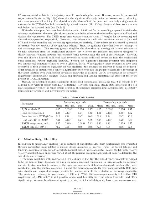
Table 5.<br />
Monte Carlo Results<br />
Parameter<br />
Ascending approach<br />
Descending approach<br />
Mean Std. dev. Min. Max. Mean Std. dev. Min. Max.<br />
L/D at Mach 25 1.05 0.0382 0.956 1.17 1.05 0.0382 0.956 1.17<br />
Peak deceleration, g 2.33 0.177 1.94 3.62 2.11 0.193 1.60 3.92<br />
Peak heat rate, BTU/(ft 2·s) 74.3 1.78 69.7 80.5 73.1 2.74 65.7 80.3<br />
Heat load, 10 4 BTU/ft 2 7.21 0.417 6.24 8.48 7.28 0.417 6.29 8.63<br />
TAEM range error, nmi 2.25 0.889 0.0838 5.63 2.46 1.12 0.155 6.75<br />
TAEM altitude, 10 3 ft 71.2 0.791 50.9 90.8 72.6 8.08 53.8 92.6<br />
C. Mission Design Flexibility<br />
In addition to uncertainty analysis, the robustness <strong>of</strong> undeflected-LBF flight per<strong>for</strong>mance was evaluated<br />
through parametric scans related to mission design quantities <strong>of</strong> interest. First, the target latitude and<br />
longitude coordinates were varied to evaluate nominal guided range capability. Second, the EI Earth-relative<br />
velocity and flight-path angle were varied about the nominal ascending approach EI point to determine the<br />
size <strong>of</strong> the entry corridor.<br />
The range capability with undeflected LBFs is shown in Fig. 13. The guided range capability is defined<br />
to be the locus <strong>of</strong> target locations <strong>for</strong> which the vehicle meets all constraints. In this case, only the accuracy<br />
and deceleration constraints are active; the peak heat rate and heat load constraints do not limit the range<br />
capability. From the nominal ascending EI point, the downrange capability covers approximately 1900 nmi,<br />
with shorter and longer downranges possible <strong>for</strong> landing sites <strong>of</strong>f the centerline <strong>of</strong> the range capability.<br />
The maximum crossrange is approximately ±660 nmi. While this crossrange capability is less than STS<br />
requirement <strong>of</strong> ±750 nmi, 23 it still provides operational flexibility <strong>for</strong> crew return from LEO and <strong>of</strong>fers<br />
significant per<strong>for</strong>mance benefits over capsule-type entry vehicles, which typically have a maximum crossrange<br />
14 <strong>of</strong> 19<br />
American Institute <strong>of</strong> Aeronautics and Astronautics


