

Variable Angle-of-Attack Profile Entry Guidance for a Crewed Lifting ...
Variable Angle-of-Attack Profile Entry Guidance for a Crewed Lifting ...
Variable Angle-of-Attack Profile Entry Guidance for a Crewed Lifting ...

You also want an ePaper? Increase the reach of your titles
YUMPU automatically turns print PDFs into web optimized ePapers that Google loves.
constraint, using a stand-<strong>of</strong>f distance <strong>of</strong> 5 BTU/(ft 2·s) to prevent violations <strong>of</strong> the heat rate constraint. This<br />
energy depletion phase is critical <strong>for</strong> α pr<strong>of</strong>iles that result in low-C D and high-L/D values. Without sufficient<br />
deceleration early in the trajectory, these cases tend to overshoot the target or violate the deceleration<br />
constraint late in the trajectory.<br />
During the energy depletion phase, the NPC is used to identify a constant bank angle command that<br />
keeps the vehicle near the heat rate constraint. Tracking <strong>of</strong> the heat rate constraint continues until the vehicle<br />
meets two criteria: a velocity gate that is a function <strong>of</strong> the estimated drag coefficient as given in Eq. (4) and<br />
a delay timer that is a function <strong>of</strong> the estimated L/D, given by Eq. (5). Together, the velocity gate and<br />
delay timer ensure that a sufficient amount <strong>of</strong> energy is depleted such that excessive g-loading near the end<br />
<strong>of</strong> the trajectory is avoided. The HL-20 was capable <strong>of</strong> implementing a linear feedback controller to follow<br />
the heat rate constraint by maintaining a near-constant α. 20 However, the absence <strong>of</strong> α control introduces<br />
nonlinearities into the dynamics, making that approach infeasible. After the vehicle passes through the<br />
velocity gate and satisfies the delay timer, the guidance algorithm transitions to the downrange targeting<br />
phase.<br />
t delay =<br />
3. Downrange Targeting Phase<br />
v gate =<br />
{<br />
{<br />
24, 000 ft/s : C D > 0.5<br />
23, 000 ft/s : C D ≤ 0.5<br />
5 s : L/D < 1.05<br />
250 (L/D − 1.05) + 5 s : L/D ≥ 1.05<br />
After the energy depletion phase, the remaining control<br />
authority is used to steer the vehicle to the target<br />
location. During this phase, targeting is per<strong>for</strong>med<br />
using the NPC. The peak heat rate and g-<br />
loading values are computed <strong>for</strong> each trajectory solution.<br />
If the peak values violate their corresponding<br />
constraints, then the bank angle is limited to satisfy<br />
the active constraint. This is accomplished by identifying<br />
a constant bank angle that enables the vehicle<br />
to fly along the constraint in the same manner as<br />
per<strong>for</strong>med in the energy depletion phase. The vehicle<br />
is commanded to fly along this constraint until<br />
the bank angle required <strong>for</strong> range targeting results<br />
in a departure from the active constraint.<br />
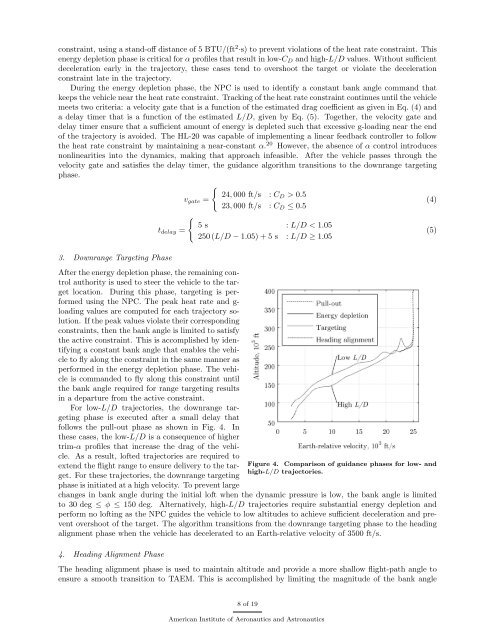
For low-L/D trajectories, the downrange targeting<br />
phase is executed after a small delay that<br />
follows the pull-out phase as shown in Fig. 4. In<br />
these cases, the low-L/D is a consequence <strong>of</strong> higher<br />
trim-α pr<strong>of</strong>iles that increase the drag <strong>of</strong> the vehicle.<br />
As a result, l<strong>of</strong>ted trajectories are required to<br />
extend the flight range to ensure delivery to the target.<br />
For these trajectories, the downrange targeting<br />
Figure 4. Comparison <strong>of</strong> guidance phases <strong>for</strong> low- and<br />
high-L/D trajectories.<br />
phase is initiated at a high velocity. To prevent large<br />
changes in bank angle during the initial l<strong>of</strong>t when the dynamic pressure is low, the bank angle is limited<br />
to 30 deg ≤ φ ≤ 150 deg. Alternatively, high-L/D trajectories require substantial energy depletion and<br />
per<strong>for</strong>m no l<strong>of</strong>ting as the NPC guides the vehicle to low altitudes to achieve sufficient deceleration and prevent<br />
overshoot <strong>of</strong> the target. The algorithm transitions from the downrange targeting phase to the heading<br />
alignment phase when the vehicle has decelerated to an Earth-relative velocity <strong>of</strong> 3500 ft/s.<br />
4. Heading Alignment Phase<br />
The heading alignment phase is used to maintain altitude and provide a more shallow flight-path angle to<br />
ensure a smooth transition to TAEM. This is accomplished by limiting the magnitude <strong>of</strong> the bank angle<br />
(4)<br />
(5)<br />
8 <strong>of</strong> 19<br />
American Institute <strong>of</strong> Aeronautics and Astronautics


