- Page 1 and 2: 9 th International Conference on Co
- Page 3 and 4: 9 th International Conference on Co
- Page 5 and 6: Frank Borasch 166 A Digital Plannin
- Page 7 and 8: A Framework for Scenario-Based Hydr
- Page 9 and 10: Fig. 2: Detail flowchart on the opt
- Page 11 and 12: to be able to solve a wide range of
- Page 13 and 14: acceleration. Similar results were
- Page 15 and 16: 3.4. Scenario results Two different
- Page 17 and 18: At sea-state 2 (H 1/3 = 0.8m) and s
- Page 19 and 20: NEU, W. L.; HUGHES, O.; MASON, W. H
- Page 21 and 22: 3. The software selection process T
- Page 23 and 24: o Development capacity of CAD vendo
- Page 25 and 26: • Departments / groups suited to
- Page 27 and 28: 1. Pre-processing: Pre-processing r
- Page 29 and 30: www.ssi.tu-harburg.de/doc/webseiten
- Page 31 and 32: propulsor should be higher than tha
- Page 33 and 34: The FRIENDSHIP Framework software d
- Page 35 and 36: ehaviour for both parameters. Table
- Page 37 and 38: Fig.13: Thrust oscillation for sing
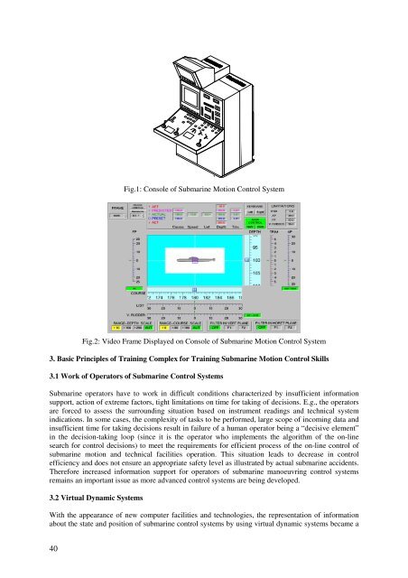
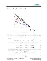
- Page 39: Training Complex for Training Subma
- Page 43 and 44: In addition, the submarine’s anim
- Page 45 and 46: Fig.8: Visualization of Operation o
- Page 47 and 48: References DORRI, M.K.; KORCHANOV,
- Page 49 and 50: The selection operator allows the t
- Page 51 and 52: This paper uses as case study the m
- Page 53 and 54: indicates the Pareto frontier with
- Page 55 and 56: Centre Girder.Max 29 28 Centre Gird
- Page 57 and 58: Though a holistic approach to the s
- Page 59 and 60: 2.5 Global Criterion Optima Enginee
- Page 61 and 62: sections in order to obtain compati
- Page 63 and 64: Max solution has been obtained for
- Page 65 and 66: Abstract Operator Decision Modeling
- Page 67 and 68: Rule 6: With the MOAS sonar (Mine a
- Page 69 and 70: 4.2. Definition: Extension The use
- Page 71 and 72: We obtain two extensions, which are
- Page 73 and 74: - We define the defaults D: ¬ dete
- Page 75 and 76: 7. Conclusion. The default logic al
- Page 77 and 78: partitioned into two sets as follow
- Page 79 and 80: 3. Two-stage stochastic programming
- Page 81 and 82: drops and the two-stage stochastic
- Page 83 and 84: Fig. 6: Unit transportation cost as
- Page 85 and 86: Fig. 10: Unit transportation cost a
- Page 87 and 88: Acknowledgements This work has been
- Page 89 and 90: Loan model: loan = 0.8 ship cost ra
- Page 91 and 92:
The effect of analyses with uncerta
- Page 93 and 94:
3.3. Requirements to the system Whe
- Page 95 and 96:
There are three design plans (1), (
- Page 97 and 98:
(a) (b) (c) Table III: Solutions fr
- Page 99 and 100:
Abstract Effects of Uncertainty in
- Page 101 and 102:
ε is a number with G\U(0,σ) and [
- Page 103 and 104:
Increasing Sigma Time Histories 1 0
- Page 105 and 106:
5.1. Space # 040: Galley and Sculle
- Page 107 and 108:
5.4. Long Term Study of Optimizatio
- Page 109 and 110:
RUN Fitness Min. ZD Avg. ZD Min. SP
- Page 111 and 112:
RUN Fitness Min ZD Avg ZD Min SP Av
- Page 113 and 114:
The Challenge in Hull Structure Bas
- Page 115 and 116:
early design stages. The main advan
- Page 117 and 118:
Profile definition is mainly based
- Page 119 and 120:
Fig. 7: Example of an automatically
- Page 121 and 122:
6.3 Other output One of the advanta
- Page 123 and 124:
welding and painting are additional
- Page 125 and 126:
To overcome these issues, a model w
- Page 127 and 128:
lightweight, hydrostatic data and t
- Page 129 and 130:
This graph yields the expected resu
- Page 131 and 132:
OERS, B.J. Van; STAPERSMA, D.; HOPM
- Page 133 and 134:
Size optimization changes only expl
- Page 135 and 136:
3.2. Topology Optimization for Conc
- Page 137 and 138:
meshed with shell elements and rema
- Page 139 and 140:
Trajectory Design for Autonomous Un
- Page 141 and 142:
drastically since it determines a l
- Page 143 and 144:
assumptions, the inertia matrix (in
- Page 145 and 146:
For each of these missions, we will
- Page 147 and 148:
more powerful than for the first tw
- Page 149 and 150:
For mission 3, using the first thru
- Page 151 and 152:
References BREIER, J.A.; RAUCH, C.G
- Page 153 and 154:
wastage from the presence of corros
- Page 155 and 156:
The MINOAS system integrates a set
- Page 157 and 158:
significant improvements over appro
- Page 159 and 160:
over the 3D CAD model of the area u
- Page 161 and 162:
through porous materials (see Stauf
- Page 163 and 164:
obustness and reliability in challe
- Page 165 and 166:
ØSTERRGAARD, E. H.; MATARIC, M. J.
- Page 167 and 168:
2 Tool integration DigiMAus integra
- Page 169 and 170:
Fig. 4 : Navisworks visualization i
- Page 171 and 172:
2.4 Office and other Visualization
- Page 173 and 174:
2.7 Control in 3D In this perspecti
- Page 175 and 176:
2.10 Method documentation The metho
- Page 177 and 178:
Clifetime Cdevelopment Csupport n :
- Page 179 and 180:
6. Why Lego Bricks? The three archi
- Page 181 and 182:
Specific own platform plug-ins are
- Page 183 and 184:
process moves from global design ac
- Page 185 and 186:
Data correctness and consistency ch
- Page 187 and 188:
Fig.4: System Architecture Once the
- Page 189 and 190:
7. Rule Based Processing Rule based
- Page 191 and 192:
The editor component is required on
- Page 193 and 194:
Geneva. ISO 215 (2004), Industrial
- Page 195 and 196:
2. Modern product model - Solid bas
- Page 197 and 198:
The built-in output formats include
- Page 199 and 200:
3.3. Global loads For the purposes
- Page 201 and 202:
Fig. 6: First eigen modes of a crud
- Page 203 and 204:
Abstract Rule-Based Resource Alloca
- Page 205 and 206:
Fig.2: User groups in the productio
- Page 207 and 208:
4 Rule-based approach 4.1 Rule defi
- Page 209 and 210:
necessity in the winter. These outd
- Page 211 and 212:
Fig.6: Decision tree for the space
- Page 213 and 214:
Abstract Combining Artificial Neura
- Page 215 and 216:
x log sig( x) = , (12) 1− − x e
- Page 217 and 218:
the simulated annealing algorithm,
- Page 219 and 220:
ecause the relation between speed a
- Page 221 and 222:
Developing of a Computer System Aid
- Page 223 and 224:
f γ A = f µ , (2) Fig. 2: Oceans
- Page 225 and 226:
calculation methods of the phenomen
- Page 227 and 228:
In a similar way can be expressed t
- Page 229 and 230:
− the relative resistance increas
- Page 231 and 232:
a) 1,0 P VE [-] 0,8 0,6 0,4 0,90 0,
- Page 233 and 234:
For the so defined service margin w
- Page 235 and 236:
Data Mining to Enhance the Throughp
- Page 237 and 238:
maneuvering time and according to w
- Page 239 and 240:
The author emphasize that reality i
- Page 241 and 242:
time intervals was not appropriate
- Page 243 and 244:
The Role of IT in Revitalizing Braz
- Page 245 and 246:
The EAS strategy is to use the Petr
- Page 247 and 248:
7. Speed to Proficiency In order to
- Page 249 and 250:
Practical Applications of Design fo
- Page 251 and 252:
Minimize Fabrication / Assembly Com
- Page 253 and 254:
Fig. 3: Example of Minor Bulkhead u
- Page 255 and 256:
5.2 Improved Practice Fig. 7: Accur
- Page 257 and 258:
many constraints on the resulting s
- Page 259 and 260:
Modeling Complex Vessels for Use in
- Page 261 and 262:
The initial position values for the
- Page 263 and 264:
means to get an insight into the sy
- Page 265 and 266:
variables. The shape of the hull is
- Page 267 and 268:
the free space available above the
- Page 269 and 270:
noise or vibration, separation of h
- Page 271 and 272:
Furthermore the approach to the imp
- Page 273 and 274:
Optimization-Based Approach to Rati
- Page 275 and 276:
• Refine or ‘fine-tune’ exist
- Page 277 and 278:
elative positions between objects.
- Page 279 and 280:
New objective scores for the design
- Page 281 and 282:
5.3 Baseline Design Selection Fig.4
- Page 283 and 284:
distance in the max-min problem. If
- Page 285 and 286:
Improvement of Interoperability bet
- Page 287 and 288:
HATLAPA models (Fig.3) are more com
- Page 289 and 290:
10. Support by VSM and VDMA (associ
- Page 291 and 292:
(DBB) approach, are restricted by t
- Page 293 and 294:
3.1.1. A process for employing the
- Page 295 and 296:
(a) (b) (c) (d) Fig.3: Option Explo
- Page 297 and 298:
Fig.7: Max. length vs. total displa
- Page 299 and 300:
Fig.9: Number of Combined Float-Mov
- Page 301 and 302:
ather than the normal approach in w
- Page 303 and 304:
ANDREWS, D.J., PAPANIKOLAOU, A; ERI
- Page 305 and 306:
2. Aspects of Production Simulation
- Page 307 and 308:
4.1 Data structure As the goal of t
- Page 309 and 310:
and used engineering tools showed d
- Page 311 and 312:
Utilization of Integrated Design an
- Page 313 and 314:
The right side in Fig. 2 illustrate
- Page 315 and 316:
Fig. 6: Initial design of hopper an
- Page 317 and 318:
In most cases, it is desired to app
- Page 319 and 320:
Interactive Hull Form Transformatio
- Page 321 and 322:
3. Modern Hull Form Representation
- Page 323 and 324:
introducing a knuckle, Fig. 3. Rule
- Page 325 and 326:
P 0 P i P’ 0 ) P’ i P′= P + i
- Page 327 and 328:
1. The initial selected vertices ar
- Page 329 and 330:
In other cases, it may be necessary
- Page 331 and 332:
face must be extended to introduce
- Page 333 and 334:
Fig 13: A prototype of the intended
- Page 335 and 336:
Abstract Aerodynamic Optimization o
- Page 337 and 338:
commonly used in wind tunnel tests,
- Page 339 and 340:
Schmode (2002) applied a RNG k-ε m
- Page 341 and 342:
Table II presents the properties of
- Page 343 and 344:
Fig.10: Comparison of exhaust conce
- Page 345 and 346:
5.2. Selected results In order to o
- Page 347 and 348:
of a zoomed in region, namely a meg
- Page 349 and 350:
performance. The derivation of the
- Page 351 and 352:
each agent can always apply rule #1
- Page 353 and 354:
With four vehicles the area that ca
- Page 355 and 356:
References AKYILDIZ, I.F.; POMPILI,
- Page 357 and 358:
However, there is no global optimum
- Page 359 and 360:
are adjusted. The calculations are
- Page 361 and 362:
Fig. 3: Deep water trim curve for m
- Page 363 and 364:
consumption is analysed over relati
- Page 365 and 366:
3.2 Benefits for crew and ship mana
- Page 367 and 368:
A 3D Packing Approach for the Early
- Page 369 and 370:
of these changes. Subsequently, Sec
- Page 371 and 372:
• Soft object. Soft objects also
- Page 373 and 374:
such that the overlapping part is r
- Page 375 and 376:
• Connection object. Connection o
- Page 377 and 378:
main difference is that the topside
- Page 379 and 380:
Two objectives were maximised: pack
- Page 381 and 382:
ASMARA, A.; NIENHUIS,U. (2006), Aut
- Page 383 and 384:
Fig.1: General arrangement of the t
- Page 385 and 386:
Group Steady-state modeling Group A
- Page 387 and 388:
Fig.7: Architecture of Cascade-forw
- Page 389 and 390:
2.2.1. Calculation of steady state
- Page 391 and 392:
Fig.15: Scatter plot of model outpu
- Page 393 and 394:
Because of the usage of steady stat
- Page 395 and 396:
Nomenclature c coefficient & fit-fa
- Page 397 and 398:
Fig.1: Petroglyph of, possibly, a c
- Page 399 and 400:
The lack of a graphical user interf
- Page 401 and 402:
3.3. CAD supported logical modellin
- Page 403 and 404:
often used in the ship industry, bu
- Page 405 and 406:
7.2. Logical components Logical com
- Page 407 and 408:
So, input facilities are an integra
- Page 409 and 410:
A Decision Support Framework for th
- Page 411 and 412:
Some measures will change the fuel
- Page 413 and 414:
The re-active technical abatements
- Page 415 and 416:
adding water into the chamber. The
- Page 417 and 418:
selection of air emission controls
- Page 419 and 420:
I = I ∩ I ∩ I and I ⊂ I VOA V
- Page 421 and 422:
The objective function in an optimi
- Page 423 and 424:
MALLACH, E.G. (1994), Understanding
- Page 425 and 426:
etween Kristiansand in Norway and H
- Page 427 and 428:
validation dataset. In a recent ser
- Page 429 and 430:
(a) (b) Fig. 6: IR corridor test (a
- Page 431 and 432:
Fig.9: Number of passengers in each
- Page 433 and 434:
4. Conclusions Two passenger ship a
- Page 435 and 436:
positive effects on the energy effi
- Page 437 and 438:
higher fuel saving potentials and a
- Page 439 and 440:
For vessels with azimuthing pods in
- Page 441 and 442:
4. Use Case Examples The methodolog
- Page 443 and 444:
4.5. Losses and Load Distribution T
- Page 445 and 446:
Fig. 7: Mission tab The software pr
- Page 447 and 448:
The methodology thus places itself
- Page 449 and 450:
Development of a Methodology for Ca
- Page 451 and 452:
2.2 Process Driver Fig. 1: Processe
- Page 453 and 454:
Fig. 4 illustrates the product info
- Page 455 and 456:
Reconstruct calculation An addition
- Page 457 and 458:
References BENTIN, M.; SMIDT, F.; P
- Page 459 and 460:
While the path for the integration
- Page 461 and 462:
ultimately, zero in on the best des
- Page 463 and 464:
Below, the subject of collaboration
- Page 465 and 466:
1 P opt (C*) C opt (P*) 0 C* 0 1 Fi
- Page 467 and 468:
Most importantly: design constraint
- Page 469 and 470:
include, for example 5 : z 1 1 = 1/
- Page 471 and 472:
Z 1 , which is in this figure is sh
- Page 473 and 474:
It can be concluded that the goal o
- Page 475 and 476:
Behavior Models can be built from t
- Page 477 and 478:
GOUGOULIDIS, G. (2008), The Utiliza
- Page 479 and 480:
This procedure can be regarded as a
- Page 481 and 482:
corrosion, coating, deformation, cr
- Page 483 and 484:
detect an indication of a crack? Wh
- Page 485 and 486:
Product Data Management is a concep
- Page 487 and 488:
Project Part Instances is a relatio
- Page 489 and 490:
The starting point of the developme
- Page 491 and 492:
Abstract Requirements of a Common D
- Page 493 and 494:
Requirements management or system e
- Page 495 and 496:
However the industry has still not
- Page 497 and 498:
When design offices begin creating
- Page 499 and 500:
Fig. 5: Ship documentation as manag
- Page 501 and 502:
Although engineering objects are th
- Page 503 and 504:
Fig. 8: Example of UUID as implemen
- Page 505 and 506:
Abdel-Maksoud 28 Abramowski 213,221