

Caution: This document contains mixed page sizes ... - Cummins Onan
Caution: This document contains mixed page sizes ... - Cummins Onan
Caution: This document contains mixed page sizes ... - Cummins Onan

Create successful ePaper yourself
Turn your PDF publications into a flip-book with our unique Google optimized e-Paper software.
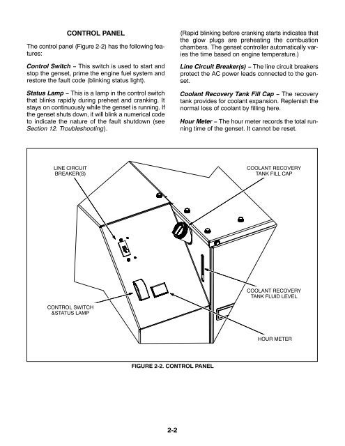
CONTROL PANEL<br />
The control panel (Figure 2-2) has the following features:<br />
Control Switch − <strong>This</strong> switch is used to start and<br />
stop the genset, prime the engine fuel system and<br />
restore the fault code (blinking status light).<br />
Status Lamp − <strong>This</strong> is a lamp in the control switch<br />
that blinks rapidly during preheat and cranking. It<br />
stays on continuously while the genset is running. If<br />
the genset shuts down, it will blink a numerical code<br />
to indicate the nature of the fault shutdown (see<br />
Section 12. Troubleshooting).<br />
(Rapid blinking before cranking starts indicates that<br />
the glow plugs are preheating the combustion<br />
chambers. The genset controller automatically varies<br />
the time based on engine temperature.)<br />
Line Circuit Breaker(s) − The line circuit breakers<br />
protect the AC power leads connected to the genset.<br />
Coolant Recovery Tank Fill Cap − The recovery<br />
tank provides for coolant expansion. Replenish the<br />
normal loss of coolant by filling here.<br />
Hour Meter − The hour meter records the total running<br />
time of the genset. It cannot be reset.<br />
LINE CIRCUIT<br />
BREAKER(S)<br />
COOLANT RECOVERY<br />
TANK FILL CAP<br />
COOLANT RECOVERY<br />
TANK FLUID LEVEL<br />
CONTROL SWITCH<br />
&STATUS LAMP<br />
HOUR METER<br />
FIGURE 2-2. CONTROL PANEL<br />
2-2


