

Caution: This document contains mixed page sizes ... - Cummins Onan
Caution: This document contains mixed page sizes ... - Cummins Onan
Caution: This document contains mixed page sizes ... - Cummins Onan

Create successful ePaper yourself
Turn your PDF publications into a flip-book with our unique Google optimized e-Paper software.
WARNING Accidental or remote starting can<br />
cause severe personal injury or death. Before<br />
removing a housing panel or access door, disconnect<br />
the negative (−) cable at the battery to<br />
prevent the engine from starting.<br />
GOVERNOR ACTUATOR<br />
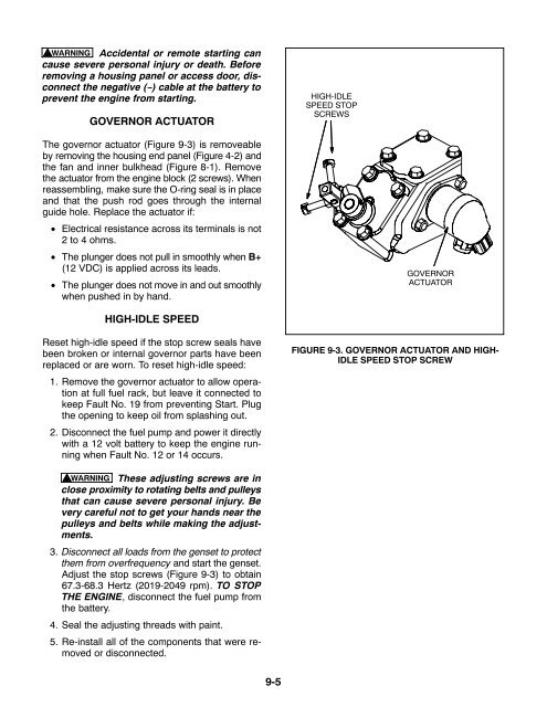
HIGH-IDLE<br />
SPEED STOP<br />
SCREWS<br />
The governor actuator (Figure 9-3) is removeable<br />
by removing the housing end panel (Figure 4-2) and<br />
the fan and inner bulkhead (Figure 8-1). Remove<br />
the actuator from the engine block (2 screws). When<br />
reassembling, make sure the O-ring seal is in place<br />
and that the push rod goes through the internal<br />
guide hole. Replace the actuator if:<br />
• Electrical resistance across its terminals is not<br />
2 to 4 ohms.<br />
• The plunger does not pull in smoothly when B+<br />
(12 VDC) is applied across its leads.<br />
• The plunger does not move in and out smoothly<br />
when pushed in by hand.<br />
GOVERNOR<br />
ACTUATOR<br />
HIGH-IDLE SPEED<br />
Reset high-idle speed if the stop screw seals have<br />
been broken or internal governor parts have been<br />
replaced or are worn. To reset high-idle speed:<br />
1. Remove the governor actuator to allow operation<br />
at full fuel rack, but leave it connected to<br />
keep Fault No. 19 from preventing Start. Plug<br />
the opening to keep oil from splashing out.<br />
2. Disconnect the fuel pump and power it directly<br />
with a 12 volt battery to keep the engine running<br />
when Fault No. 12 or 14 occurs.<br />
FIGURE 9-3. GOVERNOR ACTUATOR AND HIGH-<br />
IDLE SPEED STOP SCREW<br />
WARNING These adjusting screws are in<br />
close proximity to rotating belts and pulleys<br />
that can cause severe personal injury. Be<br />
very careful not to get your hands near the<br />
pulleys and belts while making the adjustments.<br />
3. Disconnect all loads from the genset to protect<br />
them from overfrequency and start the genset.<br />
Adjust the stop screws (Figure 9-3) to obtain<br />
67.3-68.3 Hertz (2019-2049 rpm). TO STOP<br />
THE ENGINE, disconnect the fuel pump from<br />
the battery.<br />
4. Seal the adjusting threads with paint.<br />
5. Re-install all of the components that were removed<br />
or disconnected.<br />
9-5


