

Caution: This document contains mixed page sizes ... - Cummins Onan
Caution: This document contains mixed page sizes ... - Cummins Onan
Caution: This document contains mixed page sizes ... - Cummins Onan

You also want an ePaper? Increase the reach of your titles
YUMPU automatically turns print PDFs into web optimized ePapers that Google loves.
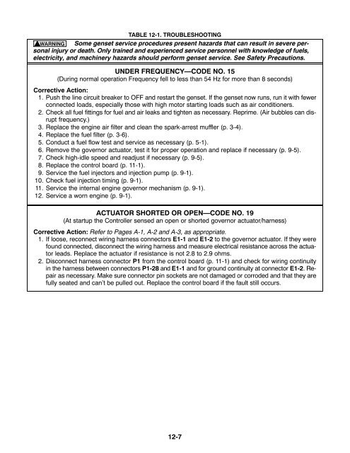
TABLE 12-1. TROUBLESHOOTING<br />
WARNING Some genset service procedures present hazards that can result in severe personal<br />
injury or death. Only trained and experienced service personnel with knowledge of fuels,<br />
electricity, and machinery hazards should perform genset service. See Safety Precautions.<br />
UNDER FREQUENCY—CODE NO. 15<br />
(During normal operation Frequency fell to less than 54 Hz for more than 8 seconds)<br />
Corrective Action:<br />
1. Push the line circuit breaker to OFF and restart the genset. If the genset now runs, run it with fewer<br />
connected loads, especially those with high motor starting loads such as air conditioners.<br />
2. Check all fuel fittings for fuel and air leaks and tighten as necessary. Reprime. (Air bubbles can disrupt<br />
frequency.)<br />
3. Replace the engine air filter and clean the spark-arrest muffler (p. 3-4).<br />
4. Replace the fuel filter (p. 3-6).<br />
5. Conduct a fuel flow test and service as necessary (p. 5-1).<br />
6. Remove the governor actuator, test it for proper operation and replace if necessary (p. 9-5).<br />
7. Check high-idle speed and readjust if necessary (p. 9-5).<br />
8. Replace the control board (p. 11-1).<br />
9. Service the fuel injectors and injection pump (p. 9-1).<br />
10. Check fuel injection timing (p. 9-1).<br />
11. Service the internal engine governor mechanism (p. 9-1).<br />
12. Service a worn engine (p. 9-1).<br />
ACTUATOR SHORTED OR OPEN—CODE NO. 19<br />
(At startup the Controller sensed an open or shorted governor actuator/harness)<br />
Corrective Action: Refer to Pages A-1, A-2 and A-3, as appropriate.<br />
1. If loose, reconnect wiring harness connectors E1-1 and E1-2 to the governor actuator. If they were<br />
found connected, disconnect the wiring harness and measure electrical resistance across the actuator<br />
leads. Replace the actuator if resistance is not 2.8 to 2.9 ohms.<br />
2. Disconnect harness connector P1 from the control board (p. 11-1) and check for wiring continuity<br />
in the harness between connectors P1-28 and E1-1 and for ground continuity at connector E1-2. Repair<br />
as necessary. Make sure connector pin sockets are not damaged or corroded and that they are<br />
fully seated and can’t be pulled out. Replace the control board if the fault still occurs.<br />
12-7


